前言
-
之前的文章《如何学习verilog,如何快速入门?》中提到了verilog学习,推荐了一个可以练习的网站:hdlbits网站,那自己也玩玩这个网站。
-
这篇文章,是接着《verilog练习:hdlbits网站上的做题笔记(4)》写的!
3.2 Sequential Logic
3.2.1 Latches and Flip-Flops
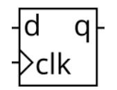
3.2.1.1 D flip-flop(Dff)
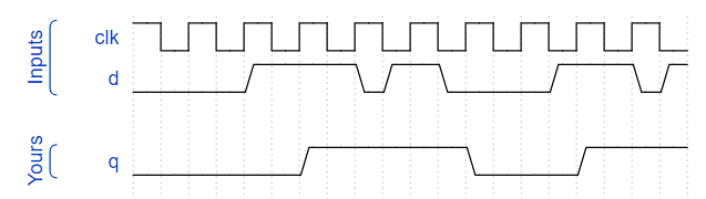
A D flip-flop is a circuit that stores a bit and is updated periodically, at the (usually) positive edge of a clock signal.
D flip-flops are created by the logic synthesizer when a clocked always block is used . A D flip-flop is the simplest form of “blob of combinational logic followed by a flip-flop” where the combinational logic portion is just a wire.
Create a single D flip-flop.
module top_module (
    input clk,    // Clocks are used in sequential circuits
    input d,
    output reg q );//

    // Use a clocked always block
    //   copy d to q at every positive edge of clk
    //   Clocked always blocks should use non-blocking assignments
    always@(posedge clk)begin
    	q <= d;
    end
endmodule
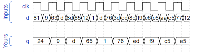
3.2.1.2 D flip-flops(dff8)
module top_module (
    input clk,
    input [7:0] d,
    output [7:0] q
);
	always@(posedge clk)begin
    	q <= d;
    end
endmodule
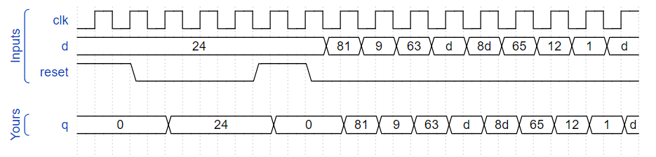
3.2.1.3 DFF with reset(Dff8r)
创建具有高电平有效同步复位的8 D触发器。所有DFF应由clk的上升沿触发。
module top_module (
    input clk,
    input reset,            // Synchronous reset
    input [7:0] d,
    output [7:0] q
);
	always@(posedge clk)begin//同步复位的D触发器
        if(reset)
            q <= 'd0;
        else
    		q <= d;
    end
endmodule
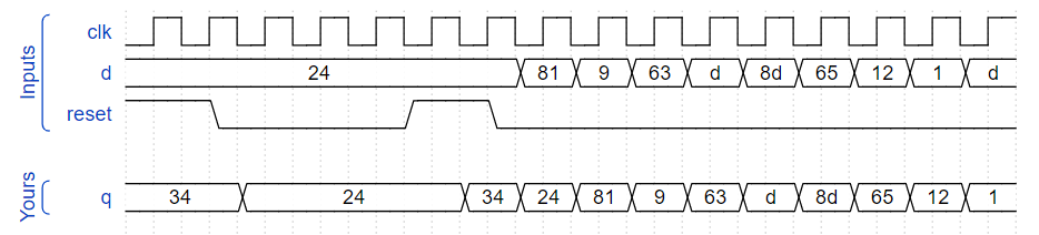
3.2.1.4 DFF with reset value(Dff8p)
Create 8 D flip-flops with active high synchronous reset. The flip-flops must be reset to 0x34 rather than zero. All DFFs should be triggered by the negative edge of clk.
module top_module (
    input clk,
    input reset,
    input [7:0] d,
    output [7:0] q
);

    always@(negedge clk)begin//同步复位的D触发器,复位值为34
        if(reset)
            q <= 'h34;
        else
    		q <= d;
    end
endmodule
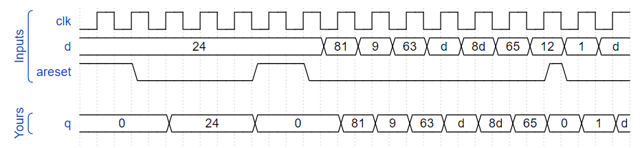
3.2.1.5 DFF with asynchronous reset(Dff8ar)
Create 8 D flip-flops with active high asynchronous reset. All DFFs should be triggered by the positive edge of clk.
module top_module (
    input clk,
    input areset,   // active high asynchronous reset
    input [7:0] d,
    output [7:0] q
);
    always@(posedge clk or posedge areset )begin//异步复位的触发器(复位与寄存不能一起操作)
        if(areset)
            q <= 'd0;
        else
    		q <= d;
    end

endmodule
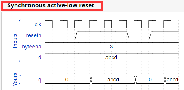
3.2.1.6 DFF with byte enable(Dff16e)
Create 16 D flip-flops. It’s sometimes useful to only modify parts of a group of flip-flops. The byte-enable inputs control whether each byte of the 16 registers should be written to on that cycle. byteena[1] controls the upper byte d[15:8], while byteena[0] controls the lower byte d[7:0].
resetn is a synchronous, active-low reset.
All DFFs should be triggered by the positive edge of clk.
module top_module (
    input clk,
    input resetn,
    input [1:0] byteena,
    input [15:0] d,
    output [15:0] q
);
    always@(posedge clk)begin
        if(!resetn)
            q<='d0;
        else
            case(byteena)
                2'b11:q<=d;
                2'd10:q[15:8]<=d[15:8];
                2'b01:q[7:0]<=d[7:0];
                default:q<=q;
            endcase
    end


endmodule
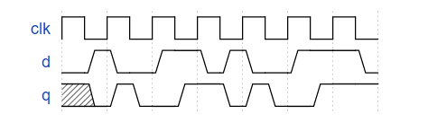
3.2.1.7 D Latch(Exams/m2014 q4a)
锁存器
//书上都说,不补全if...else...,case等可能会产生锁存器,
//但是我想问问,锁存器与寄存器的区别是什么?
//为什么下面这个,补全了else,还是生成了锁存器?
module top_module (
    input d,
    input ena,
    output q);
    always@(*)
        if(ena)
            q = d;
        else
            q = q;
endmodule
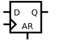
3.2.1.8 DFF(Exams/m2014 q4b)
module top_module (
    input clk,
    input d,
    input ar,   // asynchronous reset
    output q);
    always@(posedge clk or posedge ar)
        if(ar)
        q <= 'd0;
    else
        q<=d;
endmodule
3.2.1.9 DFF(Exams/m2014 q4c)
同步复位
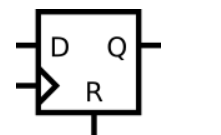
module top_module (
    input clk,
    input d,
    input r,   // synchronous reset
    output q);
    always@(posedge clk)
    if(r)
        q <= 'd0;
    else
        q <= d;
endmodule
3.2.1.10 DFF+gate(Exams/m2014 q4d)
实现以下这个电路
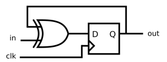
module top_module (
    input clk,
    input in,
    output out);

    always@(posedge clk)
        out <= in^out;

endmodule
3.2.1.11 Mux and DFF(mt2015_muxdff)
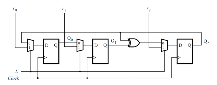
module top_module (
	input clk,
	input L,
	input r_in,
	input q_in,
	output reg Q);
    always@(posedge clk)
        if(L)
            Q <= r_in;
    	else
            Q <= q_in;

endmodule
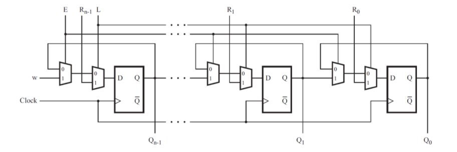
3.2.1.12 Mux and DFF(Exams/2014 q4a)
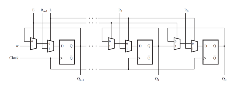
module top_module (
    input clk,
    input w, R, E, L,
    output Q
);
    always@(posedge clk)begin
        if(L)
            Q <= R;
        else if(E)
            Q <= w;
        else
            Q<= Q;
    end
endmodule
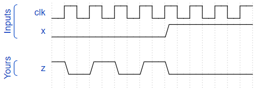
3.2.1.13 DFFs and gates(Exams/2014 q4a)
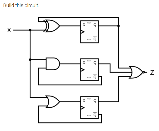
module top_module (
    input clk,
    input x,
    output z
);
    reg [2:0] q;
    always@(posedge clk)
        q <= {x|~q[2],x& ~q[1],x^q[0]};

    assign z = ~(|q);

endmodule
3.2.1.14 Create circuit from truth table(Exams/ece241 2013 q7)
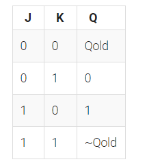
A JK flip-flop has the below truth table. Implement a JK flip-flop with only a D-type flip-flop and gates. Note: Qold is the output of the D flip-flop before the positive clock edge.
module top_module (
    input clk,
    input j,
    input k,
    output Q);

    always@(posedge clk)
        case({j,k})
            2'b00:Q<= Q;
            2'b01:Q<= 0;
            2'b10:Q<= 1;
            2'b11:Q<=~Q;
            default:;
        endcase

endmodule
3.2.1.15 Detect an edge(Edgedetect)
//第一种方法,最常见的
module top_module (
    input clk,
    input [7:0] in,
    output [7:0] pedge
);
    reg [7:0] reg_in;
    always@(posedge clk)
        reg_in <= in;

    always@(posedge clk)
        pedge <= ~reg_in & in;

endmodule
//另一种思路
module top_module (
    input clk,
    input [7:0] in,
    output [7:0] pedge
);
    reg [7:0] reg_in;
    always@(posedge clk)
        reg_in <= in;

    integer i;
    always@(posedge clk)begin
        for(i = 0; i <= 7; i = i + 1)begin
            if(in[i] & ~reg_in[i])begin
                pedge[i] <= 1'b1;
            end
            else begin
                pedge[i] <= 1'b0;
            end
        end
    end

endmodule
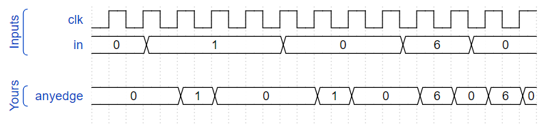
3.2.1.16 Detect both edges(Edgedetect2)
module top_module (
    input clk,
    input [7:0] in,
    output [7:0] anyedge
);
	reg [7:0] reg_in;
    always@(posedge clk)
        reg_in <= in;

    always@(posedge clk)
        anyedge <= reg_in ^ in;
endmodule
3.2.1.17 Edge capture register(Edgecapture)
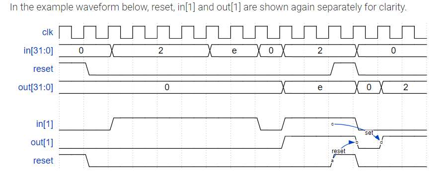
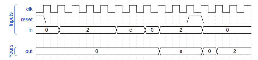
For each bit in a 32-bit vector, capture when the input signal changes from 1 in one clock cycle to 0 the next. “Capture” means that the output will remain 1 until the register is reset (synchronous reset).
捕获到下降沿一直保持为1,直到复位信号为1才变位0
Each output bit behaves like a SR flip-flop: The output bit should be set (to 1) the cycle after a 1 to 0 transition occurs. The output bit should be reset (to 0) at the positive clock edge when reset is high. If both of the above events occur at the same time, reset has precedence. In the last 4 cycles of the example waveform below, the ‘reset’ event occurs one cycle earlier than the ‘set’ event, so there is no conflict here.
module top_module (
    input clk,
    input reset,
    input [31:0] in,
    output [31:0] out
);
    wire [31:0] nedge;
    reg [31:0] reg_in;

    always@(posedge clk)
        reg_in <= in;

    assign 	nedge = reg_in & ~in;//下降沿检测
    always@(posedge clk)begin
        if(reset)
                out<= 0;
        else if(nedge!=0)
                out<=nedge|out;
        else
                out<=out;
    end

endmodule
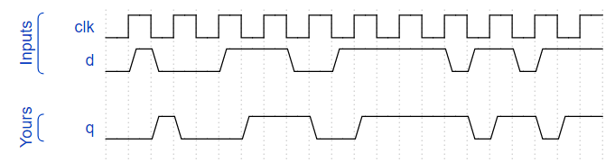
3.2.1.18 Dual-edge triggered flip-flop(Dualedge)
您熟悉在时钟的上升沿或时钟的下降沿触发的触发器。双沿触发触发器在时钟的两个边沿触发。但是,FPGA没有双沿触发触发器,因此始终不接受@(posedge clk或negedge clk)作为合法敏感性列表。
module top_module (
    input clk,
    input d,
    output q
);
	reg q_d1;
    reg q_d2;

    always@(posedge clk)begin
        q_d1 <= d ^ q_d2;
    end
    always@(negedge clk)begin
        q_d2 <= d ^ q_d1;
    end

    assign q = q_d1 ^ q_d2;

endmodule
3.2.2 Counters
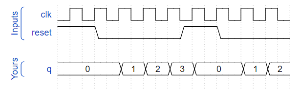
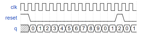
3.2.2.1 Four-bit binary counter(Count15)
构建一个4位二进制计数器,其计数范围为0到15(含0和15),其周期为16。复位输入是同步的,应将计数器复位为0。
module top_module (
    input clk,
    input reset,      // Synchronous active-high reset
    output [3:0] q);
    always@(posedge clk)begin
        if(reset)
            q <= 'd0;
        else if(q=='d15)
            q <= 'd0;
        else
            q <= q + 1'b1;
    end
endmodule
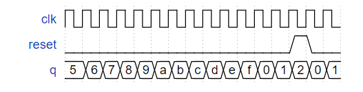
3.2.2.2 Decade counter(Count10)
建立一个十进制计数器,该计数器的计数范围为0到9(含0和9),周期为10。复位输入是同步的,应将计数器复位为0。
module top_module (
    input clk,
    input reset,        // Synchronous active-high reset
    output [3:0] q);
    always@(posedge clk)begin
    	if(reset)
           q <= 'd0;
        else if(q=='d9)
            q <= 'd0;
        else
            q <= q + 1'b1;
    end

endmodule
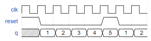
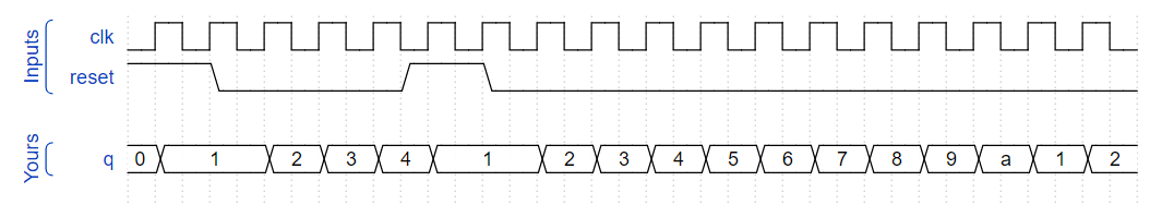
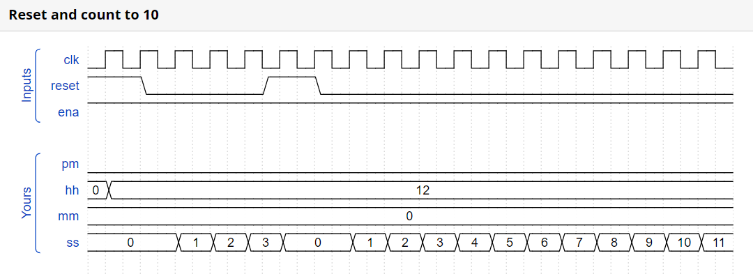
3.2.2.3 Decade counter again(Count1to10)
做一个十进制计数器,计数范围为1到10(含1和10)。复位输入是同步的,应将计数器复位为1。
module top_module (
    input clk,
    input reset,
    output [3:0] q);

	always@(posedge clk)begin
    	if(reset)
            q <= 'd1;
        else if(q=='d10)
            q <= 'd1;
        else
            q <= q + 1'b1;
    end
endmodule
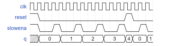
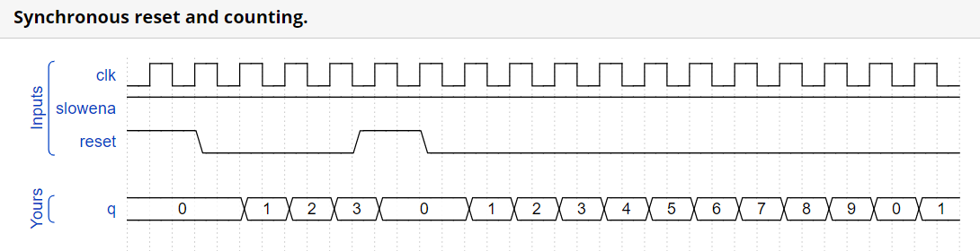
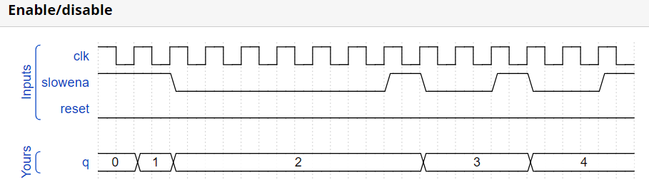
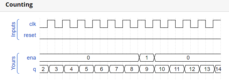
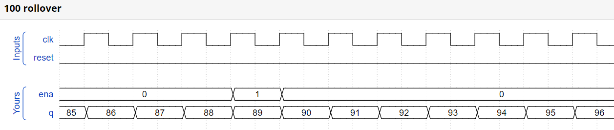
3.2.2.4 Slow decade counter(Countslow)
建立一个十进制计数器,该计数器的计数范围为0到9(含0和9),周期为10。复位输入是同步的,应将计数器复位为0。我们希望能够暂停计数器,而不是总是在每个时钟周期都递增,因此,slowena输入指示计数器应何时递增。
module top_module (
    input clk,
    input slowena,
    input reset,
    output [3:0] q);

	always@(posedge clk)begin
    	if(reset)
            q <= 'd0;
        else if(slowena)begin
            if(q=='d9)
                q <= 'd0;
            else
                q <= q + 1'b1;
        end
    end

endmodule
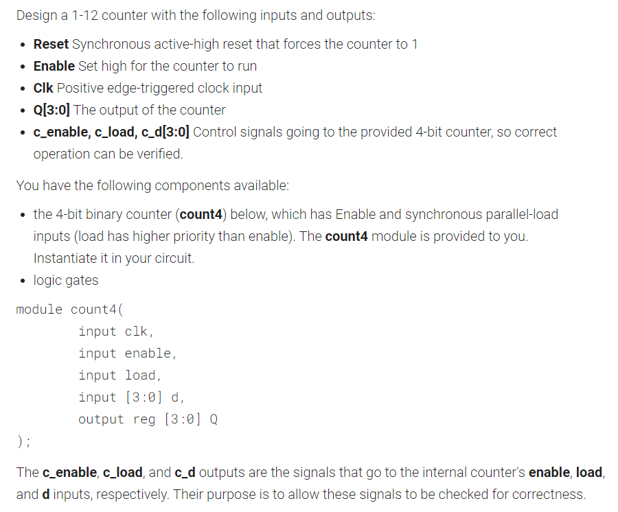
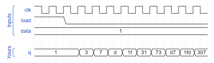
3.2.2.5 Counter 1-12(Exams/ece241 2014 q7a)
module top_module (
    input clk,
    input reset,
    input enable,
    output [3:0] Q,
    output c_enable,
    output c_load,
    output [3:0] c_d
);
	assign c_enable = enable;
    assign c_load = reset | ((Q == 4'd12) && enable == 1'b1);
    assign c_d = c_load ? 4'd1 : 4'd0;
    count4 the_counter (
        .clk	(clk		),
        .enable	(c_enable	),
        .load	(c_load		),
        .d		(c_d 		),
        .Q		(Q			)
    );

endmodule
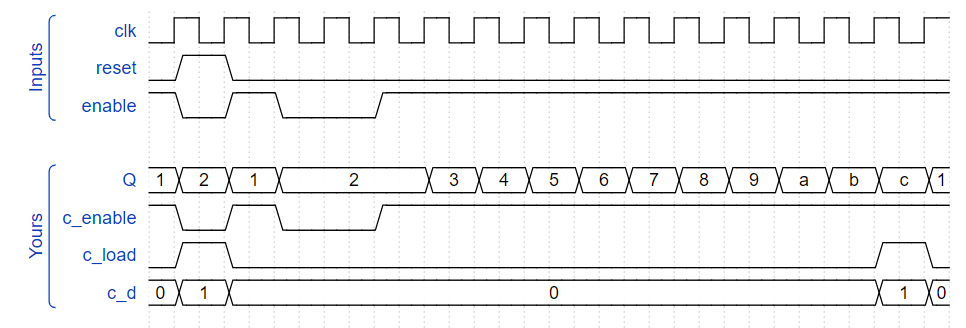
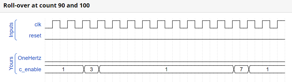
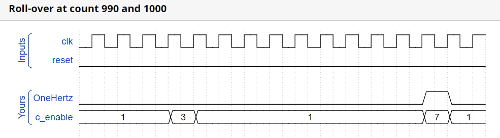
3.2.2.6 Counter 1000(Exams/ece241 2014 q7b)
The following BCD counter is provided for you. Enable must be high for the counter to run. Reset is synchronous and set high to force the counter to zero. All counters in your circuit must directly use the same 1000 Hz signal.

module bcdcount (
	input clk,
	input reset,
	input enable,
	output reg [3:0] Q
);
module top_module (
    input clk,
    input reset,
    output OneHertz,
    output [2:0] c_enable
);

	wire [3:0] q0, q1, q2;

    assign c_enable = {q1 == 4'd9 && q0 == 4'd9, q0 == 4'd9, 1'b1};
    assign OneHertz = {q2 == 4'd9 && q1 == 4'd9 && q0 == 4'd9};

    bcdcount counter0 (clk, reset, c_enable[0], q0);
    bcdcount counter1 (clk, reset, c_enable[1], q1);
    bcdcount counter2 (clk, reset, c_enable[2], q2);

endmodule
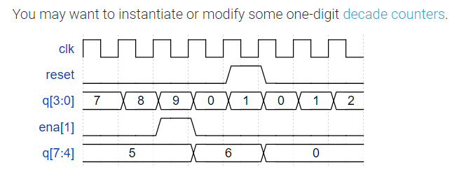
3.2.2.7 4-digit decimal counter(Countbcd)
Build a 4-digit BCD (binary-coded decimal) counter. Each decimal digit is encoded using 4 bits: q[3:0] is the ones digit, q[7:4] is the tens digit, etc. For digits [3:1], also output an enable signal indicating when each of the upper three digits should be incremented.
设计一个16位的十进制BCD计数器(个位占4位,十位占4位,百位占4位,千位占4位),然后个位进位,十位进位,百位进位时,都输出一个使能信号。
module top_module (
    input clk,
    input reset,   // Synchronous active-high reset
    output [3:1] ena,
    output [15:0] q);

    always@(posedge clk)begin
        if(reset)begin
            q <= 'd0;
        end
        else if(q[3:0] != 'd9)begin
            q[3:0] <= q[3:0] + 1'b1;
        end
        else begin
            //ena[1] <= 'd1;
            q[3:0] <= 'd0;
            q[7:4] <= q[7:4] + 1'b1;
            if(q[7:4] == 'd9)begin
                //ena[2] <= 'd1;
                q[7:4] <= 'd0;
                q[11:8] <= q[11:8] + 'd1;
                if(q[11:8] == 'd9)begin
                   // ena[3] <= 'd1;
                    q[11:8] <= 'd0;
                    q[15:12] <= q[15:12] + 'd1;
                    if(q[15:12] == 'd9)begin
                        q[15:12] <= 'd0;
                    end
                end
            end
        end
    end
    assign ena[1] = q[3:0] == 4'd9;
    assign ena[2] = q[7:4] == 4'd9 && q[3:0] == 4'd9;
    assign ena[3] = q[11:8] == 4'd9 && q[7:4] == 4'd9 && q[3:0] == 4'd9;
endmodule
//其它博客的方法!
module top_module (
    input clk,
    input reset,   // Synchronous active-high reset
    output [3:1] ena,
    output [15:0] q);

 	reg [3:0]	ones;
    reg [3:0]	tens;
    reg [3:0]	hundreds;
    reg [3:0]	thousands;

    always@(posedge clk)begin
        if(reset)begin
            ones <= 4'd0;
        end
        else if(ones == 4'd9)begin
            ones <= 4'd0;
        end
        else begin
            ones <= ones + 1'b1;
        end
    end

    always@(posedge clk)begin
        if(reset)begin
            tens <= 4'd0;
        end
        else if(tens == 4'd9 && ones == 4'd9)begin
            tens <= 4'd0;
        end
        else if(ones == 4'd9) begin
            tens <= tens + 1'b1;
        end
    end

    always@(posedge clk)begin
        if(reset)begin
            hundreds <= 4'd0;
        end
        else if(hundreds == 4'd9 && tens == 4'd9 && ones == 4'd9)begin
            hundreds <= 4'd0;
        end
        else if(tens == 4'd9 && ones == 4'd9) begin
            hundreds <= hundreds + 1'b1;
        end
    end

    always@(posedge clk)begin
        if(reset)begin
            thousands <= 4'd0;
        end
        else if(thousands == 4'd9 && hundreds == 4'd9 && tens == 4'd9 && ones == 4'd9)begin
            thousands <= 4'd0;
        end
        else if(hundreds == 4'd9 && tens == 4'd9 && ones == 4'd9) begin
            thousands <= thousands + 1'b1;
        end
    end

    assign q = {thousands, hundreds, tens, ones};
    assign ena[1] = (ones == 4'd9) ? 1'b1 : 1'b0;
    assign ena[2] = (tens == 4'd9 && ones == 4'd9) ? 1'b1 : 1'b0;
    assign ena[3] = (hundreds == 4'd9 && tens == 4'd9 && ones == 4'd9) ? 1'b1 : 1'b0;

endmodule
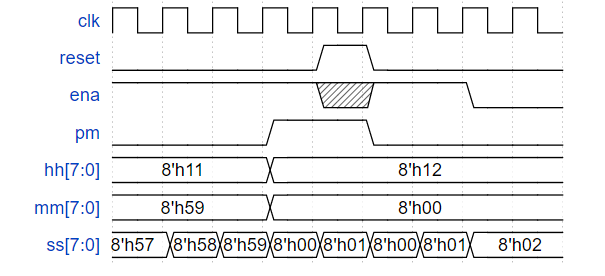
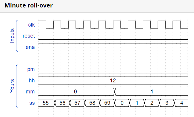
3.2.2.8 12-hour clock(Count clock)
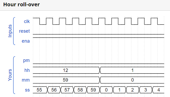
Create a set of counters suitable for use as a 12-hour clock (with am/pm indicator). Your counters are clocked by a fast-running clk, with a pulse on ena whenever your clock should increment (i.e., once per second).
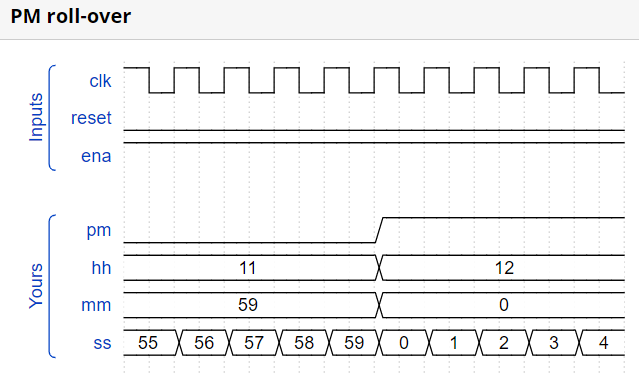
reset resets the clock to 12:00 AM. pm is 0 for AM and 1 for PM. hh, mm, and ss are two BCD (Binary-Coded Decimal) digits each for hours (01-12), minutes (00-59), and seconds (00-59). Reset has higher priority than enable, and can occur even when not enabled.
The following timing diagram shows the rollover behaviour from 11:59:59 AM to 12:00:00 PM and the synchronous reset and enable behaviour.
//第一种方法:从秒开始计算!
module top_module(
    input clk,
    input reset,
    input ena,
    output pm,
    output [7:0] hh,
    output [7:0] mm,
    output [7:0] ss);

    always@(posedge clk)begin
        if(reset)begin//12:00 AM. pm is 0 for AM and 1 for PM
            pm <= 'd0;
            hh[3:0] <= 'd2;
            hh[7:4] <= 'd1;
            mm[3:0] <= 'd0;
            mm[7:4] <= 'd0;
            ss[3:0] <= 'd0;
            ss[7:4] <= 'd0;
        end
        else if(ena)begin
            if(ss[3:0]!=9)begin
                ss[3:0] <= ss[3:0] + 'd1;
            end
       		else begin
                ss[3:0] <= 'd0;
            	ss[7:4]<= ss[7:4]+'d1;
                if(ss[7:4] == 'd5)begin
                    ss[7:4] <= 'd0;
                    mm[3:0] <= mm[3:0] + 'd1;
                    if(mm[3:0] == 'd9)begin
                        mm[3:0] <= 'd0;
                        mm[7:4] <= mm[7:4] + 'd1;
                        if(mm[7:4]==5)begin
                            mm[7:4] <= 'd0;
                            hh[3:0]<= hh[3:0] + 'd1;
                            if(hh[3:0] == 'd9)begin
                                hh[3:0] <= 'd0;
                            	hh[7:4] <= hh[7:4] + 'd1;
                            end
                            if(hh[7:4]=='d1 && hh[3:0]== 'd1)begin
                                hh[3:0] <= hh[3:0] + 'd1;
                                pm <= ~pm;
                            end
                            if(hh[7:4]=='d1 && hh[3:0] == 'd2)begin
                                hh[7:4] <= 'd0;
                                hh[3:0] <= 'd1;
                            end
                        end
                    end
                end
            end
        end
    end

endmodule
//编译都没有通过,是错的!本来想分块再写一种的,结果没写成功!
module top_module(
    input clk,
    input reset,
    input ena,
    output pm,
    output [7:0] hh,
    output [7:0] mm,
    output [7:0] ss);

    //ss低四位
    always@(posedge clk)begin
        if(reset)begin
            ss[3:0] <= 'd0;
        end
        if(ena)begin
        	if(ss[3:0] != 'd9)begin
            	ss[3:0] = ss[3:0] + 'd1;
            end
            else begin
                ss[3:0] <= 'd0;
                ss[7:4] <= ss[7:4] + 'd1;
            end
        end
    end

    //ss高四位
    always@(posedge clk)begin
        if(reset)begin
            ss[7:4] <= 'd0;
        end
        else if(ss[7:4] != 'd5)begin
            ss[7:4] = ss[7:4] + 'd1;
        end
        else begin
            ss[7:4] <= 'd0;
            mm[3:0] <= mm[3:0] + 'd1;
        end
    end

    //mm低四位
     always@(posedge clk)begin
        if(reset)begin
            mm[3:0] <= 'd0;
        end
         else if(mm[3:0] != 'd9)begin
             mm[3:0] = mm[3:0] + 'd1;
        end
        else begin
            mm[3:0] <= 'd0;
            mm[7:4] <= mm[7:4] + 'd1;
        end
    end

	//mm高四位
     always@(posedge clk)begin
        if(reset)begin
            mm[7:4] <= 'd0;
        end
        else if(mm[7:4] != 'd5)begin
            mm[7:4] = mm[7:4] + 'd1;
        end
        else begin
            mm[7:4] <= 'd0;
            hh[3:0] <= hh[3:0] + 'd1;
        end
    end

	//hh低四位
     always@(posedge clk)begin
        if(reset)begin
            hh[3:0] <= 'd2;
        end
        else if(hh[3:0] != 'd9)begin
            hh[3:0] = hh[3:0] + 'd1;
        end
        else begin
            hh[3:0] <= 'd0;
            hh[7:4] <= hh[7:4] + 'd1;
        end
    end

	//hh高四位
     always@(posedge clk)begin
        if(reset)begin
            hh[7:4] <= 'd1;
            pm <= 'd0;
        end
        else if(hh[7:4] == 'd1 && hh[3:0]=='d1)begin
             hh[3:0] <= 'd2;
             pm <= ~pm;
        end
        else if(hh[7:4] == 'd1 && hh[3:0]=='d2)begin
            hh[3:0] <= 'd1;
            hh[7:4] <= 'd0;
        end
    end
endmodule
3.2.3 Shift Registers
3.2.3.1 4-bit shift register(Shift4)
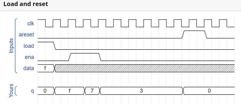
Build a 4-bit shift register (right shift), with asynchronous reset, synchronous load, and enable.
- areset: Resets shift register to zero.
- load: Loads shift register with data[3:0] instead of shifting.
- ena: Shift right (q[3] becomes zero, q[0] is shifted out and disappears).
- q: The contents of the shift register.
If both the load and ena inputs are asserted (1), the load input has higher priority.
module top_module(
    input clk,
    input areset,  // async active-high reset to zero
    input load,
    input ena,
    input [3:0] data,
    output reg [3:0] q);
    always@(posedge clk or posedge areset)begin
        if(areset)begin
           q <= 'd0;
        end
        else if(load)begin
           q <= data;
        end
        else if(ena)begin
            q <= {1'd0,q[3:1]};
        end
    end
endmodule
3.2.3.2 Left/right rotator(Rotate100)
Build a 100-bit left/right rotator, with synchronous load and left/right enable. A rotator shifts-in the shifted-out bit from the other end of the register, unlike a shifter that discards the shifted-out bit and shifts in a zero. If enabled, a rotator rotates the bits around and does not modify/discard them.
load: Loads shift register with data[99:0] instead of rotating.
ena[1:0]: Chooses whether and which direction to rotate.
- 2’b01 rotates right by one bit
- 2’b10 rotates left by one bit
- 2’b00 and 2’b11 do not rotate.
q: The contents of the rotator.
module top_module(
    input clk,
    input load,
    input [1:0] ena,
    input [99:0] data,
    output reg [99:0] q);

    always@(posedge clk)begin
        if(load) q<= data;
        else begin
            case(ena)
                2'b01: q<={q[0],q[99:1]};
                2'b10: q<={q[98:0],q[99]};
                2'b00: q<=q;
            endcase
        end
    end

endmodule
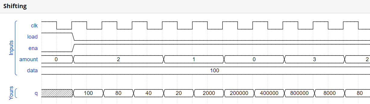
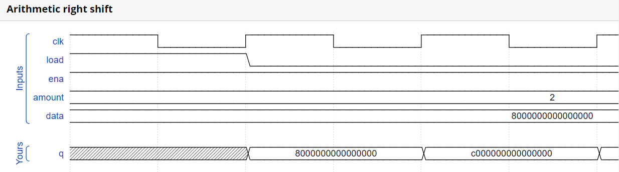
3.2.3.3 Left/right arithmetic shift by 1 or 8(Shift18)
Build a 64-bit arithmetic shift register, with synchronous load. The shifter can shift both left and right, and by 1 or 8 bit positions, selected by amount.
An arithmetic right shift shifts in the sign bit of the number in the shift register (q[63] in this case) instead of zero as done by a logical right shift. Another way of thinking about an arithmetic right shift is that it assumes the number being shifted is signed and preserves the sign, so that arithmetic right shift divides a signed number by a power of two.
load: Loads shift register with data[63:0] instead of shifting.
ena: Chooses whether to shift.
amount: Chooses which direction and how much to shift.
- 2’b00: shift left by 1 bit.
- 2’b01: shift left by 8 bits.
- 2’b10: shift right by 1 bit.
- 2’b11: shift right by 8 bits.
q: The contents of the shifter.
module top_module(
    input clk,
    input load,
    input ena,
    input [1:0] amount,
    input [63:0] data,
    output reg [63:0] q);
    always@(posedge clk)begin
        if(load)begin
        	q <= data;
        end
        else if(ena)begin
            case(amount)
                2'b00:q <= {q[62:0],1'd0};
                2'b01:q <= {q[55:0],8'd0};
                2'b10:q <= {q[63],q[63:1]};
                2'b11:q <= {{8{q[63]}},q[63:8]};//算术移位,也包含符号位的移位,对于正数来说,最高位为0,对于负数来说,最高位为1,所以进行算术移位时,如果是左移,那不用管符号位的问题,如果是右移,就要将符号位补在高位。
            endcase
        end
    end

endmodule
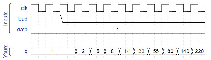
3.2.3.4 5-bit LFSR(Lfsr5)
module top_module(
    input clk,
    input reset,    // Active-high synchronous reset to 5'h1
    output [4:0] q
);
    always@(posedge clk)begin
        if(reset)begin
           q <= 'd1;
        end
        else begin
        	//q <= {q[0],q[4],q[3]^q[0],q[2:1]};
            q[0] <= q[1];
            q[1] <= q[2];
            q[2] <= q[3] ^ q[0];
            q[3] <= q[4];
            q[4] <= q[0];
        end
    end
endmodule
3.2.3.5 3-bit LFSR(Mt2015 lfsr)
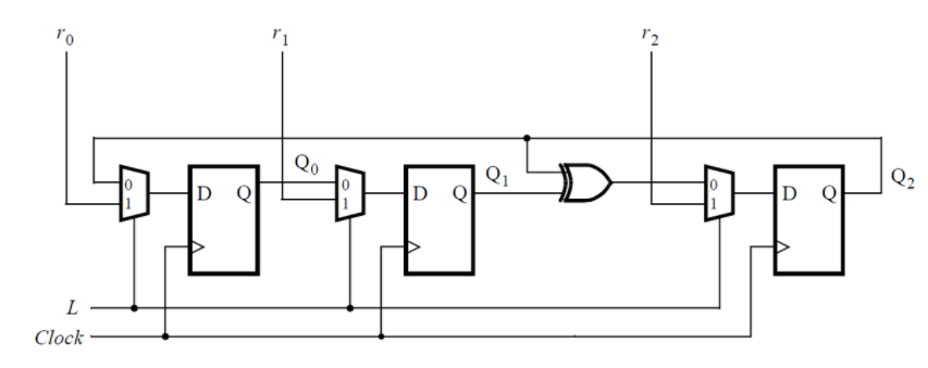
module top_module (
	input [2:0] SW,      // R
	input [1:0] KEY,     // L and clk
	output [2:0] LEDR);  // Q

    always@(posedge KEY[0])begin
        if(KEY[1])
            LEDR <= SW;
    	else
            LEDR <= {LEDR[1]^LEDR[2],LEDR[0],LEDR[2]};
    end

endmodule
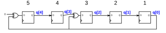
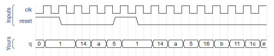
3.2.3.6 32-bit LFSR(Lfsr32)
//什么?
Build a 32-bit Galois LFSR with taps at bit positions 32, 22, 2, and 1.
module top_module(
    input clk,
    input reset,    // Active-high synchronous reset to 32'h1
    output [31:0] q
);
   always@(posedge clk)begin
        if(reset)begin
           q <= 'd1;
        end
        else begin
            //q <= {q[0],q[4],q[3]^q[0],q[2:1]};
            q <= {q[0],q[31:23],q[22]^q[0],q[21:3],q[2]^q[0],q[1]^q[0]};
        end
    end

endmodule
3.2.3.7 Shift register(Exams/m2014 q4k)
module top_module (
    input clk,
    input resetn,   // synchronous reset
    input in,
    output out);

    reg [3:0] out_reg;

    always@(posedge clk)begin
        if(resetn == 1'b0)begin
            out_reg <= 4'd0;
        end
        else begin
            out_reg <= {out_reg[2:0], in};
        end
    end

    assign out = out_reg[3];

endmodule
3.2.3.8 Shift register(Exams/m2014 q4b)
module top_module (
    input [3:0] SW,
    input [3:0] KEY,
    output [3:0] LEDR
); //

    MUXDFF u1_MUXDFF(
        .clk            (KEY[0]	),
        .w		(KEY[3]	),
        .R		(SW[3]	),
        .E		(KEY[1]	),
        .L		(KEY[2]	),
        .Q		(LEDR[3])
    );
    MUXDFF u2_MUXDFF(
        .clk	        (KEY[0]	),
        .w		(LEDR[3]),
        .R		(SW[2]	),
        .E		(KEY[1]	),
        .L		(KEY[2]	),
        .Q		(LEDR[2])
    );
    MUXDFF u3_MUXDFF(
        .clk	        (KEY[0]	),
        .w		(LEDR[2]),
        .R		(SW[1]	),
        .E		(KEY[1]	),
        .L		(KEY[2]	),
        .Q		(LEDR[1])
    );
    MUXDFF u4_MUXDFF(
        .clk	        (KEY[0]	),
        .w		(LEDR[1]),
        .R		(SW[0]	),
        .E		(KEY[1]	),
        .L		(KEY[2]	),
        .Q		(LEDR[0])
    );


endmodule

module MUXDFF (
    input clk,
    input w, R, E, L,
    output Q
);
    always@(posedge clk)begin
        if(L)begin
            Q <= R;
        end
        else begin
            if(E)begin
                Q <= w;
            end
            else begin
                Q <= Q;
            end
        end
    end

endmodule
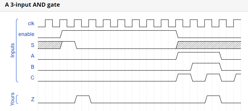
3.2.3.9 3-input LUT(Exams/ece241 2013 q12)
module top_module (
    input clk,
    input enable,
    input S,
    input A, B, C,
    output Z );

    reg [7:0] q;

    always @(posedge clk) begin
        if (enable) q <= {q[6:0], S};
    end
    assign Z = q[ {A, B, C} ];
endmodule
3.2.4 More Circuits
Cellular automata
3.2.4.1 Rule 90(Rule90)
The rules are simple. There is a one-dimensional array of cells (on or off). At each time step, the next state of each cell is the XOR of the cell’s two current neighbours. A more verbose way of expressing this rule is the following table, where a cell’s next state is a function of itself and its two neighbours:
(The name “Rule 90” comes from reading the “next state” column: 01011010 is decimal 90.)
//第一种写法
module top_module(
    input clk,
    input load,
    input [511:0] data,
    output [511:0] q );

    integer i;
    always@(posedge clk)begin
        if(load)begin
           q <= data;
        end
        else begin
            for(i=0;i < 512;i= i+1)begin
                if(i==0) q[i] <= q[i+1] ;
                 else if(i == 511) q[i] <= q[i-1];
                 else q[i]<= q[i+1]^q[i-1];
            end
        end
    end

endmodule
//另一种写法
module top_module(
    input clk,
    input load,
    input [511:0] data,
    output [511:0] q );

    always@(posedge clk)begin
        if(load)begin
            q <= data;
        end
        else begin
            q <= {1'b0, q[511:1]} ^ {q[510:0], 1'b0};
        end
    end


endmodule
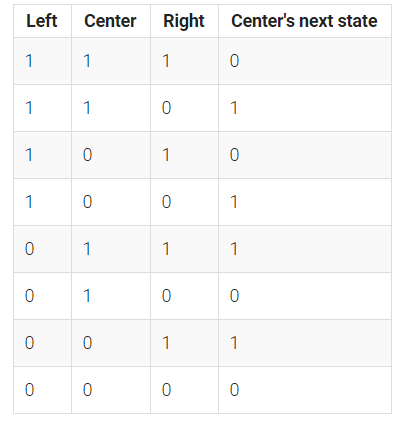
3.2.4.2 Rule 110(Rule110)
There is a one-dimensional array of cells (on or off). At each time step, the state of each cell changes. In Rule 110, the next state of each cell depends only on itself and its two neighbours, according to the following table:

(The name “Rule 110” comes from reading the “next state” column: 01101110 is decimal 110.)
//愣是写成了3-8译码器
module top_module(
    input clk,
    input load,
    input [511:0] data,
    output [511:0] q
);
	integer i;
    always@(posedge clk)begin
        if(load)begin
           q <= data;
        end
        else begin
            for(i=0;i < 512;i= i+1)begin
                if(i==0) begin
                    case({q[i+1],q[i],1'b0})
                        3'b000:q[i]<=1'b0;
                        3'b010:q[i]<=1'b1;
                        3'b100:q[i]<=1'b0;
                        3'b110:q[i]<=1'b1;
                        default:;
                    endcase
                end
                else if(i == 511) begin
                    case({1'b0,q[i],q[i-1]})
                       3'b000:q[i]<=1'b0;
                       3'b001:q[i]<=1'b1;
                       3'b010:q[i]<=1'b1;
                       3'b011:q[i]<=1'b1;
                       default:;
                    endcase
              end
              else begin
                   case({q[i+1],q[i],q[i-1]})
                       3'b000:q[i]<=1'b0;
                       3'b001:q[i]<=1'b1;
                       3'b010:q[i]<=1'b1;
                       3'b011:q[i]<=1'b1;
                       3'b100:q[i]<=1'b0;
                       3'b101:q[i]<=1'b1;
                       3'b110:q[i]<=1'b1;
                       3'b111:q[i]<=1'b0;
                       default:;
                   endcase
              end
            end
        end
    end
endmodule
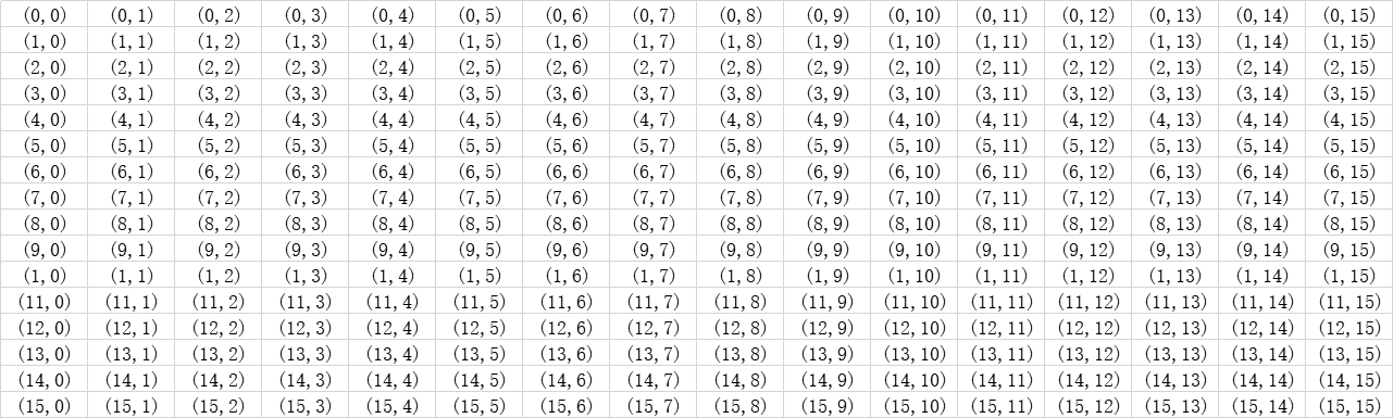
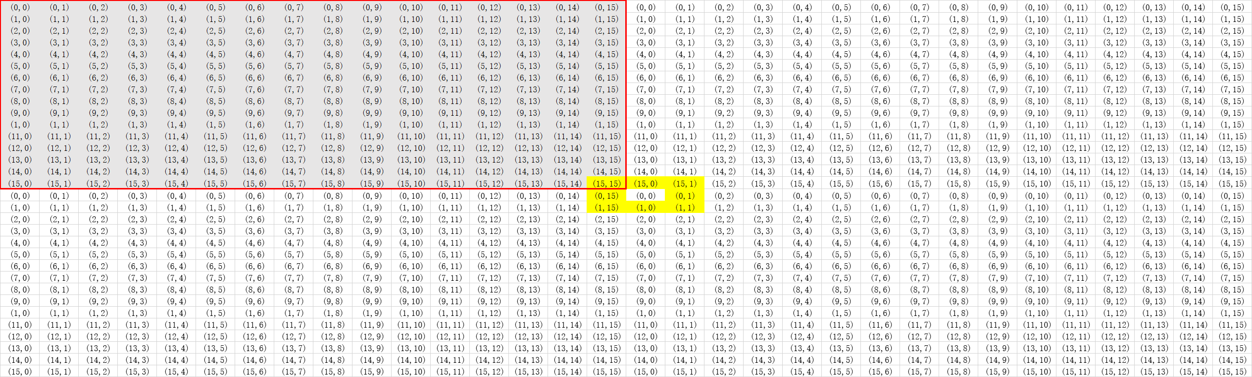
3.2.4.3 Conway’s Game of Life 16x16(Conwaylife)
The “game” is played on a two-dimensional grid of cells, where each cell is either 1 (alive) or 0 (dead). At each time step, each cell changes state depending on how many neighbours it has:
- 0-1 neighbour: Cell becomes 0.
- 2 neighbours: Cell state does not change.
- 3 neighbours: Cell becomes 1.
- 4+ neighbours: Cell becomes 0.
//抄的,如果你们想做的话,推荐试试sv的二维数组!
module top_module(
    input clk,
    input load,
    input [255:0] data,
    output [255:0] q );

    reg [3:0]	sum;
    integer i;

    always@(posedge clk)begin
        if(load)begin
            q <= data;
        end
        else begin
            for(i = 0; i <= 255; i = i + 1)begin
                if(i == 0)begin
                    sum = q[255] + q[240] + q[241] + q[15] + q[1] + q[31] + q[16] + q[17];
                end
                else if(i == 15)begin
                    sum = q[254] + q[255] + q[240] + q[14] + q[0] + q[30] + q[31] + q[16];
                end
                else if(i == 240)begin
                    sum = q[239] + q[224] + q[225] + q[255] + q[241] + q[15] + q[0] + q[1];
                end
                else if(i == 255)begin
                    sum = q[238] + q[239] + q[224] + q[254] + q[240] + q[14] + q[15] + q[0];
                end
                else if(i > 0 && i < 15)begin
                    sum = q[i + 239] + q[i + 240] + q[i + 241] + q[i - 1] + q[i + 1] + q[i + 15] + q[i + 16] + q[i + 17];
                end
                else if(i > 240 && i < 255)begin
                    sum = q[i -17] + q[i - 16] + q[i - 15] + q[i - 1] + q[i + 1] + q[i - 241] + q[i - 240] + q[i - 239];
                end
                else if(i % 16 == 0)begin
                    sum = q[i -1] + q[i - 16] + q[i - 15] + q[i + 15] + q[i + 1] + q[i + 31] + q[i + 16] + q[i + 17];
                end
                else if(i % 16 == 15)begin
                    sum = q[i -17] + q[i - 16] + q[i - 31] + q[i - 1] + q[i - 15] + q[i + 15] + q[i + 16] + q[i + 1];
                end
                else begin
                    sum = q[i - 17] + q[i - 16] + q[i - 15] + q[i - 1] + q[i + 1] + q[i + 15] + q[i + 16] + q[i + 17];
                end
                case(sum)
                    4'd2:begin
                        q[i] <= q[i];
                    end
                    4'd3:begin
                        q[i] <= 1'b1;
                    end
                    default:begin
                        q[i] <= 1'b0;
                    end
                endcase
            end
        end
    end

endmodule
最后
以上就是聪明鸡最近收集整理的关于verilog练习:hdlbits网站上的做题笔记(5)前言的全部内容,更多相关verilog练习:hdlbits网站上内容请搜索靠谱客的其他文章。


发表评论 取消回复