一.硬件原理
1.原理图
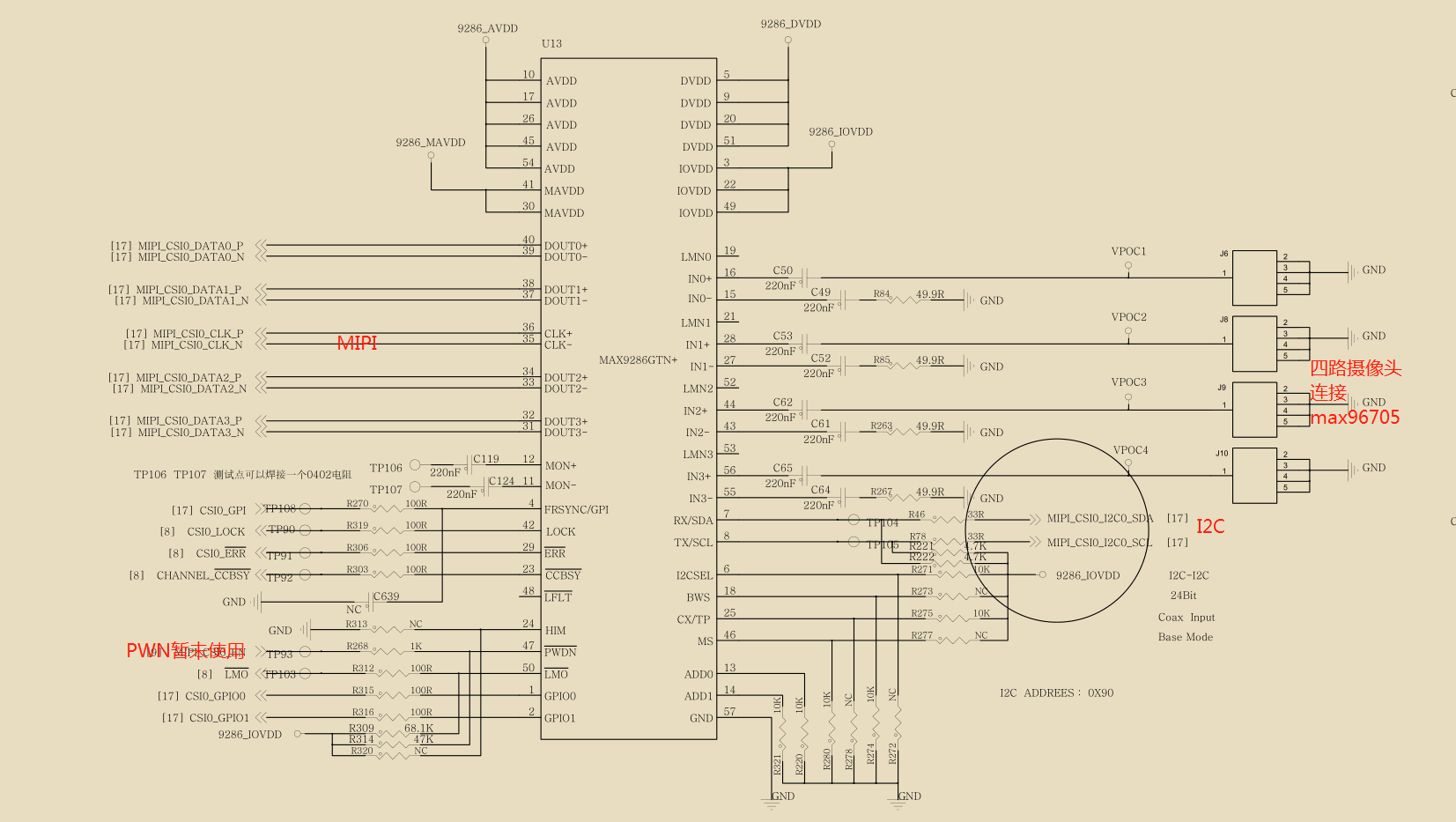
2.引脚信息
        	/* max9286 */
			SC_P_MIPI_DSI0_GPIO0_00   摄像头电源power-gpios
			SC_P_MIPI_CSI0_MCLK_OUT    摄像头信号触发,需要26HZ的pwm,gpi-gpios
			SC_P_ADC_IN0         pwn-gpios
            /* i2c */
            SC_P_MIPI_CSI0_I2C0_SDA
            SC_P_MIPI_CSI0_I2C0_SCL
3.DTS
pinctrl_max9286: csi_pwn{
			fsl,pins = <
				SC_P_MIPI_CSI0_GPIO0_00_LSIO_GPIO1_IO27		0x18000000
				SC_P_MIPI_CSI0_MCLK_OUT_LSIO_GPIO1_IO24		0x18000000
				SC_P_ADC_IN0_LSIO_GPIO3_IO18	0x18000000
				SC_P_SPDIF0_TX_LSIO_GPIO2_IO15	0x1C000020
				//SC_P_MIPI_DSI1_GPIO0_01_LSIO_GPIO1_IO23		0x1C000000 //Camera_PWR_EN
				SC_P_MIPI_DSI0_GPIO0_00_LSIO_GPIO1_IO18		0x1C000000
			>;
   };

 	i2c0_mipi_csi0: i2c@58226000 {

		compatible = "fsl,imx8qm-lpi2c";
		assigned-clocks = <&clk_post IMX8QM_CSI0_I2C0_CLK>;
		assigned-clock-rates = <24000000>;
		status = "okay";
		max9286_mipi@48	 {
			compatible = "maxim,max9286_mipi";
			reg = <0x48>;
			pinctrl-0 = <&pinctrl_max9286>;
			pinctrl-names = "default";
			clocks = <&clk IMX8QM_CLK_DUMMY>;
			clock-names = "capture_mclk";
			mclk = <81000000>;
			mclk_source = <0>;
			pwn-gpios = <&gpio3 18 GPIO_ACTIVE_HIGH>;
			power-gpios = <&gpio1 18 GPIO_ACTIVE_HIGH>;
			gpi-gpios = <&gpio1 24 GPIO_ACTIVE_HIGH>;
			virtual-channel;
			port {
				max9286_0_ep: endpoint {
				remote-endpoint = <&mipi_csi0_ep>;
				data-lanes = <1 2 3 4>;
				};
			};
		};
	};

 &isi_0 {
	status = "okay";
};

&isi_1 {
	status = "okay";
};

&isi_2 {
	status = "okay";
};

&isi_3 {
	status = "okay";
};
4.kernel config
CONFIG_IMX8_MEDIA_DEVICE=m
CONFIG_VIDEO_V4L2_SUBDEV_API=y
# CONFIG_USB_GSPCA is not set
CONFIG_V4L_PLATFORM_DRIVERS=y
CONFIG_VIDEO_MXC_CAPTURE=y
CONFIG_VIDEO_MX8_CAPTURE=y
CONFIG_IMX8_CAPTURE_DRIVER=m
CONFIG_IMX8_MIPI_CSI2=m
CONFIG_MXC_CAMERA_OV5640_MIPI_V3=m
CONFIG_GMSL_MAX9286=m
CONFIG_CAMERA_ACTION=m
CONFIG_VIDEO_MXC_CSI_CAMERA=y
CONFIG_MXC_MIPI_CSI=y
CONFIG_MXC_CAMERA_OV5640_MIPI_V2=y
CONFIG_V4L_MEM2MEM_DRIVERS=y
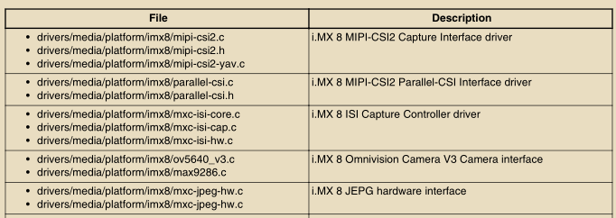
5.驱动文件介绍
6.9286地址配置:
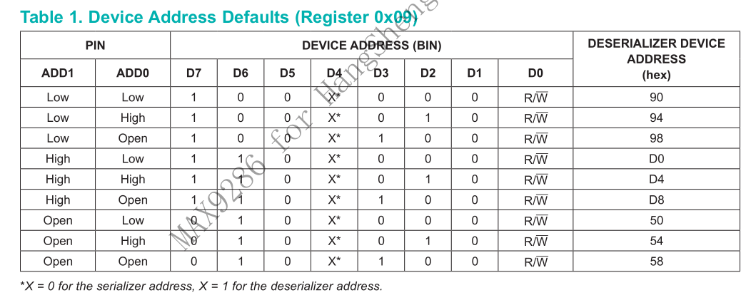
ADD0 ADD1都为low,所以地址为0x48
二.如何抓取摄像头视频数据
imx-test例程里面有v4l2将摄像头的buffer映射到drm的buffer里面。
mx8_v4l2_cap_drm_64 -cam 1 -fmt RGBP -ow 1280 -oh 720 -fr 30
用法如下:
mx8_v4l2_cap_drm_64
 -num <numbers of frame need to be captured>
 -of save to file
 -l <device support list>
 -log <log level, 6 will show all message>
 -cam <device index> 0bxxxx,xxxx
 -d "/dev/videoX" if user use this option, -cam should be 1
 -p test performance, need to combine with "-of" option
 -m <mode> specify camera sensor capture mode(mode:0, 1, 2, 3, 4)
 -fr <frame_rate> support 15fps and 30fps
 -fmt <format> support XR24, AR24, RGBP, RGB3, BGR3, YUV4, YM24, YUYV and NV12, only XR24, AR24 and RGBP support playback
 -ow <width> specify output width
 -oh <height> specify output height
 -hflip <num> enable horizontal flip, num: 0->disable or 1->enable
 -vflip <num> enable vertical flip, num: 0->disable or 1->enable
 -alpha <num> enable and set global alpha for camera, num equal to 0~255
example:
./mx8_cap -cam 1        capture data from video0 and playback
./mx8_cap -cam 3        capture data from video0/1 and playback
./mx8_cap -cam 7 -of    capture data from video0~2 and save to 0~2.BX24
./mx8_cap -cam 255 -of  capture data from video0~7 and save to 0~7.BX24
./mx8_cap -cam 0xff -of capture data from video0~7 and save to 0~7.BX24
./mx8_cap -cam 1 -fmt NV12 -of capture data from video0 and save to 0.NV12
./mx8_cap -cam 1 -of -p test video0 performace
三.问题点
目前碰到的问题:
max9286+max96705目前官方使用Automatic Mode(内同步),需要设置9286 0x06~0x08寄存器。而我们拿到的摄像头是采用外同步,只需要将max9286的gpi脚设置成26hz的pwm波即可。
目前有以下问题:
1.camera的电源需要arm这边控制。
已解决,camera有专用的电源脚,命名为power-gpio.
2.内同步就是根据9286的06, 07,08三个寄存器的值来设置帧同步的周期,而目前采用的是外同步,怎么判断是内还是外同步?
将9286 gpi引脚直接拉高,然后上电看是否有摄像头数据出来,有则表示是外同步,因为内同步需要设置帧同步时钟,以下为摄像头数据。CSI波形如下:

3.如何设置96705的线序,96705是8bit的时候,通过设置crossbar,来调整线序如:
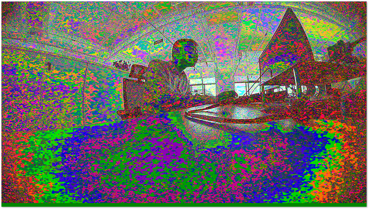
目前摄像头crossbar是从那边拿到的数据才行,不然出来的图片颜色不正确,如下:
/* STEP 15 cross bar writes */
max9271_write_reg(max9286_data, 0, 0x20, 0x07);
max9271_write_reg(max9286_data, 0, 0x21, 0x06);
max9271_write_reg(max9286_data, 0, 0x22, 0x05);
max9271_write_reg(max9286_data, 0, 0x23, 0x04);
max9271_write_reg(max9286_data, 0, 0x24, 0x03);
max9271_write_reg(max9286_data, 0, 0x25, 0x02);
max9271_write_reg(max9286_data, 0, 0x26, 0x01);
max9271_write_reg(max9286_data, 0, 0x27, 0x00);
max9271_write_reg(max9286_data, 0, 0x30, 0x17);
max9271_write_reg(max9286_data, 0, 0x31, 0x16);
max9271_write_reg(max9286_data, 0, 0x32, 0x15);
max9271_write_reg(max9286_data, 0, 0x33, 0x14);
max9271_write_reg(max9286_data, 0, 0x34, 0x13);
max9271_write_reg(max9286_data, 0, 0x35, 0x12);
max9271_write_reg(max9286_data, 0, 0x36, 0x11);
max9271_write_reg(max9286_data, 0, 0x37, 0x10);

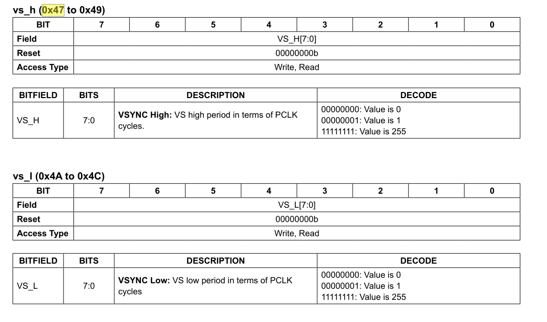
4.外同步需要设置行、场同步周期(VS generator configure),由以下寄存器(0x47~0x4c)设置,如果不进行设置则无法与96705进行lock,就没有信号过来,lock脚为低:
9286和96705能否进行链路还需满足以下要求,在max9286 datesheet中找到如下:
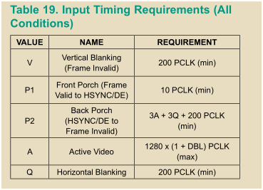

上图可知,场信号是低有效.pclk是74.25M。
V指一场高电平时间不能小于200 pclk
P1指场前肩(场无效信号)大于10PCLK
P2指场后肩大于3(A+Q)+200PCLK
A行有效信号时间
Q行无效信号
目前我们主要只需配置V F就好了,设置如下:
/* STEP 16 VS high period in terms of PCL cycles*/
max9271_write_reg(max9286_data, 0, 0x47, 0x00);
max9271_write_reg(max9286_data, 0, 0x48, 0x01);
max9271_write_reg(max9286_data, 0, 0x49, 0x90);
/* STEP 17 VS low period in terms of PCL cycles*/
max9271_write_reg(max9286_data, 0, 0x4A, 0x25);
max9271_write_reg(max9286_data, 0, 0x4B, 0xBA);
max9271_write_reg(max9286_data, 0, 0x4C, 0x4D);
算法如下:
V=400(0x190) F=2472525(0x25BA4D)
V = 400 /(74.25*1000000) = 5.39ms
F = 2472525/(74.25*1000000) = 33.3ms
FPS(帧率) = 1/(5.39+33.3) * 1000 ≈ 26HZ
5.目前max9286硬件配置是BWS=0(24bit),CX/TP=1,I2CSEL=1,HIM=1 ,MS=1,需要匹配设置摄像头96705参数。
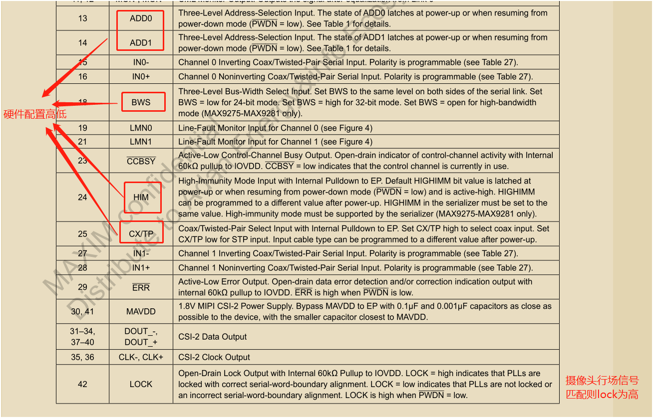
摄像头软件配置: uyvy格式,外同步, YUV422 8bit,PCLK 74.25MHz
MAX96705 摄像头硬件设置 BWS=0 CX/TP=1 I2CSEL=1 HIM=1 MS/HVEN=1
主机端MAX9286 硬件设置 BWS=0 CX/TP=1 I2CSEL=1 HIM=1 MS=1
以上为硬件工程师修改。
6.多个摄像头不同步,camera传过来的图像有问题。
主要原因是帧同步时钟没设置好,应该选择GPI为帧同步输入脚,而且是26HZ图像才不会出现问题,不然会出现下面这样:

之前调试一直是把FRSYNC/GPI引脚拉高,先搞清楚内外同步模式选择和不同。
GPI定义如下:
GPI: The serializer’s GPO (or INT) outputs follow GPI (when FSYNCMODE = 11)
0x01 = 0x11000010 (C2)
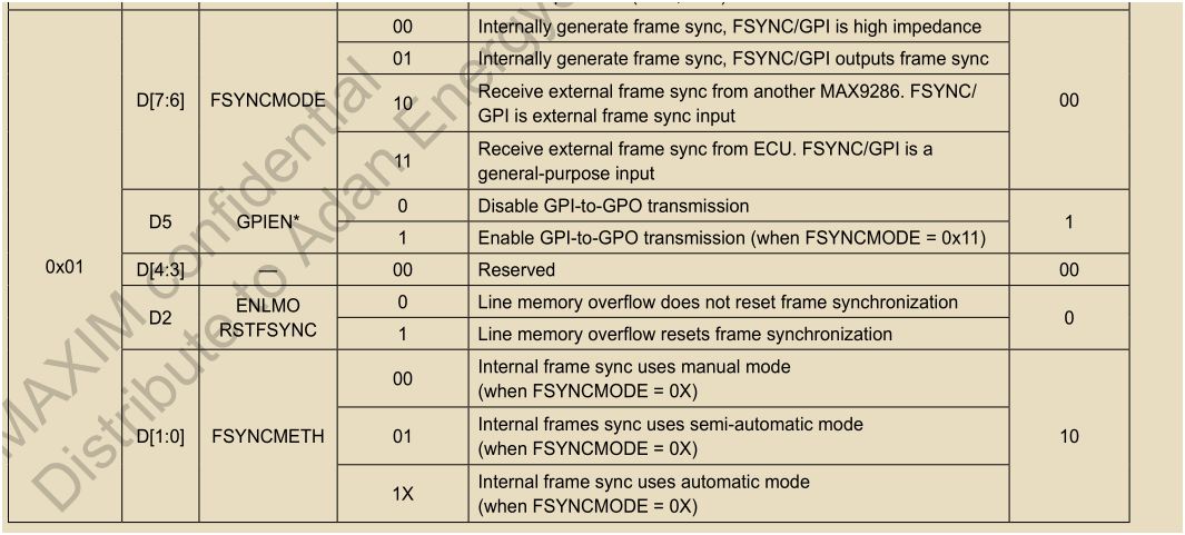
D[7:6]是选择同步模式:
00 使用内部帧时钟同步,GPI口为高阻抗。
01 使用内部帧时钟同步,GPI口输出帧同步时钟。
10 接收另一个9286的帧同步信号,GPI口是外部的帧同步输入。
11 接收ECU的帧同步信号。
D[1:0]是选择同步方法:
00 手动模式,需要设置同步时钟则需设置0x06~0x08寄存器。
01 半自动模式
1x 自动模式
解释一下这几个模式:
● Manual Mode (FSYNCMETH = 00)
FSYNCPERIOD bits (registers 0x06 to 0x08) manu-ally set the frame sync period. Manual mode allows a frame sync period up to 2 24 PCLK cycles (~16.8million).
● Automatic Mode (FSYNCMETH = 1X)
(Figure 46)The deserializer sends frame sync after counting VSYNC pulses (determined by FSYNCPERDIV) on the slowest link (auto mode) or master link (semi-auto mode). After the last VSYNC pulse, and timing mar-gins adjustments (set by KVAL and PVAL), the dese-rializer sends frame sync. FSYNC is locked when all VSYNCs are aligned (within the margin DIFF),and FSYNC occurs within the timing margin (KVAL,PVAL) for two consecutive VSYNC cycles. PVAL is specified in PCLK cycles while KVAL is specified in absolute time units.
● Semi-Automatic Mode (FSYNCMETH = 01)
The device operates similar to automatic mode with the following differences: The deserializer does not check the skew between different serial links (DIFF). Timing margins adjustments (KVAL, PVAL) are measured from the master link (as opposed to the slowest link).
网友问题点:
1.用v4l2_cap获取视频时,色彩不对,如下:

发现他们camera输入格式设置如下:

也就是说CSC的src_fmt是上面这种。
查看支持表,根据函数:
mxc-isi-cap.c
struct mxc_isi_fmt *mxc_isi_get_src_fmt(struct v4l2_subdev_format *sd_fmt)
{
	u32 index;

	/* two fmt RGB32 and YUV444 from pixellink */
	if (sd_fmt->format.code == MEDIA_BUS_FMT_YUYV8_1X16 ||
		sd_fmt->format.code == MEDIA_BUS_FMT_YVYU8_2X8 ||
		sd_fmt->format.code == MEDIA_BUS_FMT_AYUV8_1X32 ||
		sd_fmt->format.code == MEDIA_BUS_FMT_UYVY8_2X8)
		index = 1;
	else
		index = 0;
	return &mxc_isi_src_formats[index];
}
其中UYVY格式应该设置成MEDIA_BUS_FMT_UYVY8_2X8才能被认为是YUV格式的,所以修改成MEDIA_BUS_FMT_UYVY8_2X8格式就好了。
三.代码
指出几个重要寄存器:
96705:
max9271_write_reg(max9286_data, 0, 0x07, 0x94);
max9271_write_reg(max9286_data, 0, 0x04, 0x43);
max9271_write_reg(max9286_data, 0, 0x42, 0x5F);
9286:
max9286_write_reg(max9286_data, 0x12, 0xF3);
max9286_write_reg(max9286_data, 0x01, 0xE2);
驱动代码在我的下载列表里,如下:
https://download.csdn.net/download/u011784994/13773582
有不懂的可以留言。
最后
以上就是忧郁冬天最近收集整理的关于max9286+max96705摄像头调试--基于imx8qm一.硬件原理二.如何抓取摄像头视频数据的全部内容,更多相关max9286+max96705摄像头调试--基于imx8qm一内容请搜索靠谱客的其他文章。


发表评论 取消回复