七.STM32F030C8T6 MCU开发之TIMER模块级联组成32BIT计时器案例
文章目录
- 七.STM32F030C8T6 MCU开发之TIMER模块级联组成32BIT计时器案例
- 0.总体功能概述
- 1.TIM硬件介绍
- 1.1 TIM1/3级联硬件介绍
- 1.1.1 主从模式介绍
- 1.1.2 TIM1为主,TIM3为从,TIM3 的输入触发源选择
- 1.1.3 Master and slave synchronization
- 1.2 TIM3/2 级联进行输入捕获的硬件介绍
- 1.2.1 Master and slave synchronization
- 2.TIM 1/3 级别的32BIT计时器的软件配置
- 3.验证效果
- 3.1 打印结果
- 4.总结
0.总体功能概述
使用STD库–en.stm32f0_stdperiph_lib_v1.6.0。
低成本版stm32芯片(比如F0系列)不具有32位计时器,自带的TIM均为16位。
某些对于计时要求高的场合,而STM32F0单片机16位的定时器最多计数65535,那么很明显us级别的计时只能维持65.535ms,有时候解算过程可能不止65.535ms,因此需要级联组成一个32位定时器作为计数器或者计时器。甚至,你还可以继续级联,用3个计时器组成48位计时器,当然我只测试到了32位,更多级联有待测试。
本案例TIM1由48M分频后的1MHZ系统时钟驱动,TIM3由TIM1计满产生的信号1HZ驱动.
由于TIM1 只支持16BIT,无法实现1us计时器功能,利用TIM1的高级定时间repeat功能,分250次重复计算,也就是TIM1是40us为计数单位的计时器
TIM3 实现秒计时器功能
1.TIM硬件介绍

1.1 TIM1/3级联硬件介绍

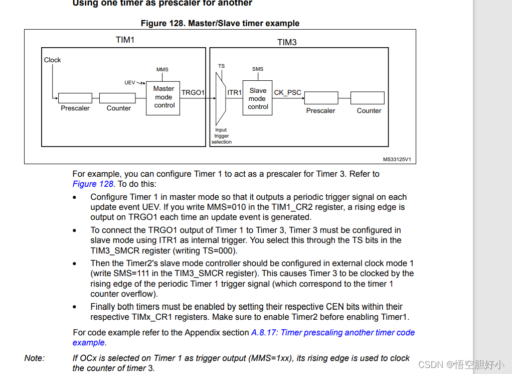
1.1.1 主从模式介绍
主模式:定时器使能只受驱动时钟控制或者输出控制信号(TRGO)。
从模式:
a.复位模式, 在发生一个触发输入事件时,计数器和它的预分频器能够重新被初始化;同时,如果IMx_CR1寄存器的URS 位为低,还产生一个更新事件UEV ;然后所有的预装载寄存器(TIMx_ARR ,TIMx_CCRx)都被更新了。
b.从模式:门控模式, 计数器的使能依赖于选中的输入端的电平。
c.从模式:触发模式, 计数器的使能依赖于选中的输入端上的事件。
d.从模式:外部时钟模式,
The slave mode can be:
Reset mode: rising edge of the selected trigger input (TRGI)
reinitializes the counter and generates an update of the registers.
Gated mode: the counter clock is enabled when the trigger input (TRGI) is high.
The counter stops (but is not reset) as soon as the trigger becomes low.
Both start and stop of the counter are controlled.
Trigger mode: the counter starts at a rising edge of the trigger TRGI (but it is not reset).
Only the start of the counter is controlled.
External clock mode 1: rising edges of the selected trigger (TRGI) clock the counter.
1.1.2 TIM1为主,TIM3为从,TIM3 的输入触发源选择

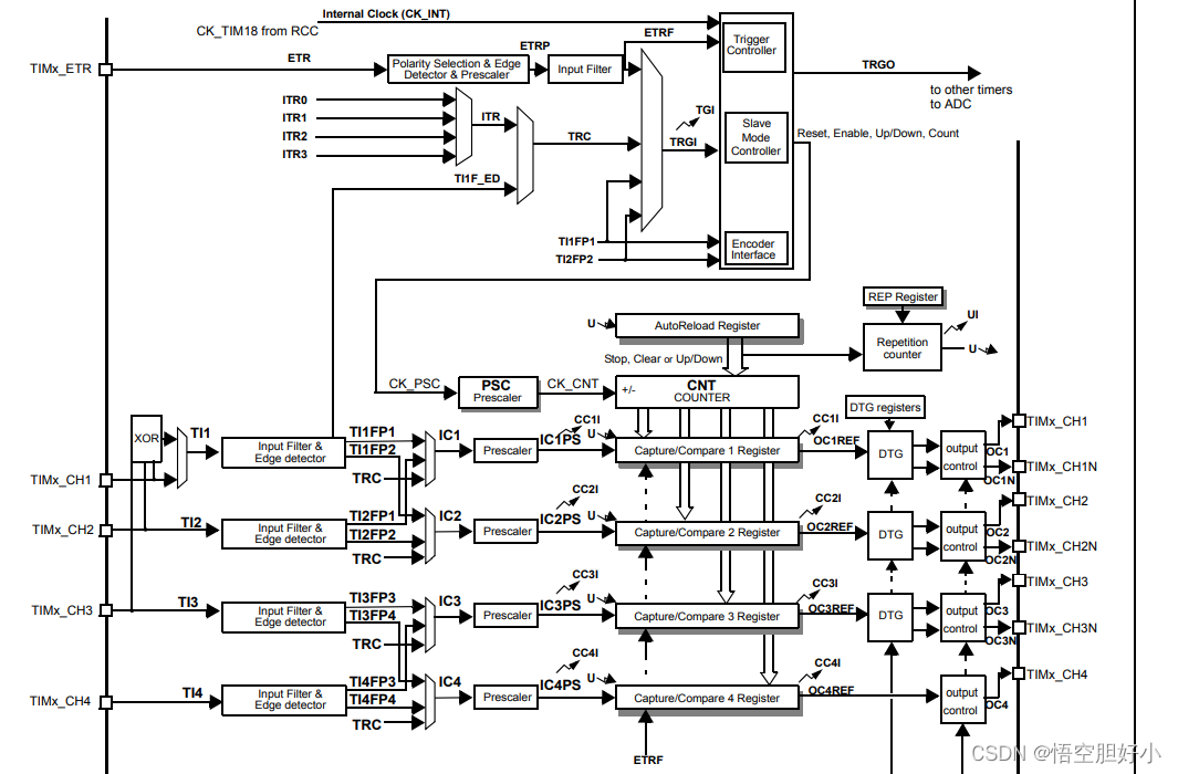
ITRx由TS位确定,TIM3工作在从模式下内部触发时钟的可选项,如果所选器件对应的定时器不存在则该选项也不存在,如TIM3可选择TIM1_TRGO/TIM15_TRGO/TIM4_TRGO。
TIM3 的输入触发源就是 TIM3的工作基准时钟
1.1.3 Master and slave synchronization
Master configuration
• Use the master update event as the master trigger output (TRGO).
• Enable the Master/Slave mode.
Slave configuration
• Select the slave input trigger: the master trigger output (TRGO) used as the input trigger for the slave.
• Enable the Master/Slave mode.
• Use the external clock mode 1 as the Slave mode:
the slave is clocked by the update event of the master timer.
That is, when the master counter is overflow, the slave counter is incremented.
Using this configuration, each time the period to be measured exceeds the 16-bit master timer Auto-reload register,an update event is generated to clock the slave time
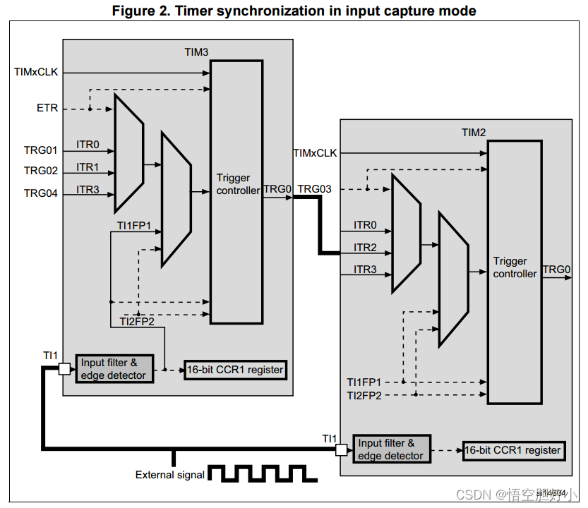
1.2 TIM3/2 级联进行输入捕获的硬件介绍
这个是其他芯片的摘要,来自ST的相关参考资料,配置流程相同

1.2.1 Master and slave synchronization
Master configuration
• Use the master update event as the master trigger output (TRGO).
• Enable the Master/Slave mode.
Slave configuration
• Select the slave input trigger: the master trigger output (TRGO) used as the input trigger for the slave.
• Enable the Master/Slave mode.
• Use the external clock mode 1 as the Slave mode:
the slave is clocked by the update event of the master timer.
That is, when the master counter is overflow, the slave counter is incremented.
Using this configuration, each time the period to be measured exceeds the 16-bit master timer Auto-reload register,an update event is generated to clock the slave time
2.TIM 1/3 级别的32BIT计时器的软件配置
void Initial_Timer1_3(void)
{
	TIM_TimeBaseInitTypeDef  TIM_TimeBaseStructure={0};
	RCC_APB2PeriphClockCmd(RCC_APB2Periph_TIM1 , ENABLE); 	/*开启时钟*/
	RCC_APB1PeriphClockCmd(RCC_APB1Periph_TIM3 , ENABLE); 	/*开启时钟*/

//slave

	TIM_TimeBaseStructure.TIM_Period = 0xffff; /*自动重装值 即从0计数到0xffff*/
	TIM_TimeBaseStructure.TIM_Prescaler = 0;	 /*71+1分频,每次计数等价于1us*/
	TIM_TimeBaseStructure.TIM_ClockDivision = TIM_CKD_DIV1;	/*不分频*/
	TIM_TimeBaseStructure.TIM_CounterMode = TIM_CounterMode_Up; /*向上计数*/
	TIM_TimeBaseInit(TIM3, &TIM_TimeBaseStructure);

	//TIM_ARRPreloadConfig(TIM3, ENABLE);/*为TIM3装载配置并使能*/
	TIM_SelectInputTrigger(TIM3, TIM_TS_ITR0);/*选择TIM3的输入触发源为TIM1 查表可以找到*/
	TIM_SelectSlaveMode(TIM3,TIM_SlaveMode_External1);//TIM_SlaveMode_External1);// TIM_SlaveMode_Trigger);/*TIM3为从模式中的复位模式*/
	TIM_UpdateRequestConfig(TIM3, TIM_UpdateSource_Regular);//TIM_UpdateSource_Global);/*计数器更新来源于计数溢出*/
	/*============================================================================*/
	TIM_SelectOutputTrigger(TIM3, TIM_TRGOSource_Update);/*选择TIM3触发输出的原因:计数器更新*/
	/*============================================================================*/
	TIM_SelectMasterSlaveMode(TIM3, TIM_MasterSlaveMode_Enable);/*使能TIM3的级联功能*/

	//master
	TIM_TimeBaseStructInit(&TIM_TimeBaseStructure);
	TIM_TimeBaseStructure.TIM_Period = 1000000/250-1; 	/*1s*/
	TIM_TimeBaseStructure.TIM_Prescaler = 48-1;   	/*47分频,每次计数等价于1us*/
	TIM_TimeBaseStructure.TIM_ClockDivision = TIM_CKD_DIV1;/*不分频*/
	TIM_TimeBaseStructure.TIM_CounterMode = TIM_CounterMode_Up; /*向上计数*/
	TIM_TimeBaseStructure.TIM_RepetitionCounter= 250-1;
	TIM_TimeBaseInit(TIM1, &TIM_TimeBaseStructure);

//	TIM_PrescalerConfig(TIM1, 0, TIM_PSCReloadMode_Update);/*不分频*/
//	TIM_UpdateDisableConfig(TIM1, ENABLE);/*暂停TIM2 等待TIM3的配置完再开启*/
	TIM_SelectSlaveMode(TIM1, TIM_SlaveMode_Reset);/*TIM3为从模式中的复位模式*/
	TIM_UpdateRequestConfig(TIM1, TIM_UpdateSource_Regular);/*计数器更新来源于计数溢出*/
	TIM_SelectOutputTrigger(TIM1,TIM_TRGOSource_Update);
	TIM_SelectMasterSlaveMode(TIM1, TIM_MasterSlaveMode_Enable);/*使能TIM2的级联功能*/

	TIM_Cmd(TIM3, ENABLE); /*启动TIM3*/
	TIM_Cmd(TIM1, ENABLE); /*启动TIM2*/
}
TIM1 的工作时钟是1MHZ,由于TIM1 只支持16BIT,无法实现1us为基础单位计时器功能,利用TIM1的高级定时间repeat功能,分250次重复计算,也就是TIM1是40us为计数单位的计时器。
TIM3 的工作时钟是TIM1的输出控制信号(TRGO),是1HZ,实现秒计时器功能。
3.验证效果
//取us级的时间读取:
/**************************实现函数********************************************
*函数原型:		uint32_t get_timer13_count(void)
*功  能:	  读取系统运行的时间 ,返回单位为us 的时间数。
*输入参数:		无
*输出参数:		处理器当前时间,从上电开始计时  单位 us
*******************************************************************************/
uint32_t get_timer13_count(void)
{

 	uint32_t temp=0 ;
 	temp = TIM3->CNT; //读高16位时间
 	temp = temp<<16;
 	temp += TIM1->CNT; //读低16位时间
 	return temp;
}

uint16_t get_timer1_count(void)
{

 	uint16_t temp=0 ;
 	temp = TIM1->CNT; //读低16位时间
 	return temp;
}
uint16_t get_timer3_count(void)
{

 	uint16_t temp=0 ;
 	temp = TIM3->CNT; //读高16位时间
 	return temp;
}
int time1_3_main(void)
{
		unsigned int s_time = 0;
		unsigned int e_time = 0;
	Initial_Timer1_3();
  while(1)
  {

    //Delay_ms(1000);
		s_time = get_curtime();
		while(1)
		{
			e_time = get_curtime();
			if(e_time>s_time )
			{
				if((e_time - s_time) >=1000)
				{
					break;
				}
			}
		}
		printf("get_timer s:m 3 1_count=%d:%drn",   get_timer3_count(),get_timer1_count());

  }
}
3.1 打印结果
[2022-11-17 18:59:02]  get_timer s:m 3 1_count=709:3254
[2022-11-17 18:59:03]  get_timer s:m 3 1_count=710:255
[2022-11-17 18:59:04]  get_timer s:m 3 1_count=711:1254
[2022-11-17 18:59:05]  get_timer s:m 3 1_count=712:2255
[2022-11-17 18:59:06]  get_timer s:m 3 1_count=713:3254
[2022-11-17 18:59:07]  get_timer s:m 3 1_count=714:254
[2022-11-17 18:59:08]  get_timer s:m 3 1_count=715:1254
[2022-11-17 18:59:09]  get_timer s:m 3 1_count=716:2255
[2022-11-17 18:59:10]  get_timer s:m 3 1_count=717:3254
4.总结
a.简单地说级联功能,即是一个定时器的定时条件满足后,可以产生一个触发信号启动另一个定时器的定时操作。
对于需要高精度并且长延时的应用,16位的定时(上述精度和时间长度)就不够了,这个问题可以有两种解决办法;
第一个办法是通过软件的接力完成,这个方法的可行性在于定时时间较长,允许软件有足够的时间介入计数,这种办法非常方便,多数情况都可使用。
第二种办法是使用STM32特有的定时器级联功能,实现32位的计数效果,因为级联是由硬件触发的,当设置好各项寄存器后,软件不必中途干预,
可以达到高精度长延时的要求。进一步地,STM32最多有四个定时器,如果串联起来,甚至可以实现4*16=64位的计数效果。
在ST的网站上有一个应用笔记和对应的例子程序,详细说明和演示了如何使用STM32的级联功能实现32位的输入捕获和32位的输出比较功能,各位可以研究一下:
应用笔记下载地址:http://www.st.com/stonline/products/literature/an/13711.pdf
b、不是所有定时器都支持定时器内部主从互联。其中部分完全不支持内部主、从互联;有的只支持从模式下的互联;
c、即使支持TIMER的互联模式,但互联的定时器及相关通道也是有相关约定的。
数效果。
在ST的网站上有一个应用笔记和对应的例子程序,详细说明和演示了如何使用STM32的级联功能实现32位的输入捕获和32位的输出比较功能,各位可以研究一下:
应用笔记下载地址:http://www.st.com/stonline/products/literature/an/13711.pdf
b、不是所有定时器都支持定时器内部主从互联。其中部分完全不支持内部主、从互联;有的只支持从模式下的互联;
c、即使支持TIMER的互联模式,但互联的定时器及相关通道也是有相关约定的。
最后
以上就是细腻板凳最近收集整理的关于七.STM32F030C8T6 MCU开发之TIMER模块级联组成32BIT计时器案例七.STM32F030C8T6 MCU开发之TIMER模块级联组成32BIT计时器案例的全部内容,更多相关七.STM32F030C8T6内容请搜索靠谱客的其他文章。


发表评论 取消回复