网络需求

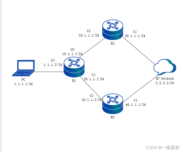
l 所有设备上都运行OSPF协议,R1上配置转发策略路由,IP Network中有IP地址为2.2.2.2/24的服务器。
l R1通过TRACK监控接口G0状态,当R1的G0接口状态为up时,PC通过R1、R2访问服务器2.2.2.2 。当R1的G0接口状态为down时,PC通过R1、R3访问服务器2.2.2.2 。
配置转发策略路由组网图
配置步骤
步骤1:
配置各接口IP地址。(略)
步骤2:
启用单播路由协议OSPF,让网络中的所有设备能相互通信。
#配置R1。
R1#configure terminal
R1(config)#router ospf 100
R1(config-ospf)#network 1.1.1.0 0.0.0.255 area 0
R1(config-ospf)#network 10.1.1.0 0.0.0.255 area 0
R1(config-ospf)#network 20.1.1.0 0.0.0.255 area 0
R1(config-ospf)#exit
#配置R2。
R2#configure terminal
R2(config)#router ospf 100
R2(config-ospf)#network 10.1.1.0 0.0.0.255 area 0
R2(config-ospf)#network 30.1.1.0 0.0.0.255 area 0
R2(config-ospf)#exit
#配置R3。
R3#configure terminal
R3(config)#router ospf 100
R3(config-ospf)#network 20.1.1.0 0.0.0.255 area 0
R3(config-ospf)#network 40.1.1.0 0.0.0.255 area 0
R3(config-ospf)#exit
#查看R1的路由表,可看到到达2.2.2.0/24网络有2个下一跳。
R1#show ip route
Codes: C - Connected, L - Local, S - static, R - RIP, B - BGP, i-ISIS
U - Per-user Static route
O - OSPF, OE-OSPF External, M - Management, E - IRMP, EX - IRMP external
C 1.1.1.0/24 is directly connected, 22:14:53, G2
L 1.1.1.1/32 is directly connected, 22:14:53, G2
O 2.2.2.0/24 [110/3] via 10.1.1.2, 00:00:09, G0
[110/3] via 20.1.1.2, 00:00:09, G1
C 10.1.1.0/24 is directly connected, 21:41:21, G0
L 10.1.1.1/32 is directly connected, 21:41:21, G0
C 20.1.1.0/24 is directly connected, 15:19:15, G1
L 20.1.1.1/32 is directly connected, 15:19:15, G1
O 30.1.1.0/24 [110/2] via 10.1.1.2, 18:55:36, G0
O 40.1.1.0/24 [110/2] via 20.1.1.2, 00:22:08, G1
C 127.0.0.0/8 is directly connected, 87:42:47, lo0
L 127.0.0.1/32 is directly connected, 87:42:47, lo0
#配置R1,修改接口G0的cost值为100,使到2.2.2.0/24网络的路由优选G1接口。
R1(config)#interface G0
R1(config-if-G0)#ip ospf cost 100
R1(config-if-G0)#exit
#查看R1的路由表。
R1#show ip route
Codes: C - Connected, L - Local, S - static, R - RIP, B - BGP, i-ISIS
U - Per-user Static route
O - OSPF, OE-OSPF External, M - Management, E - IRMP, EX - IRMP external
C 1.1.1.0/24 is directly connected, 23:27:34, G2
L 1.1.1.1/32 is directly connected, 23:27:34, G2
O 2.2.2.0/24 [110/3] via 20.1.1.2, 01:12:50, G1
C 10.1.1.0/24 is directly connected, 22:54:03, G0
L 10.1.1.1/32 is directly connected, 22:54:03, G0
C 20.1.1.0/24 is directly connected, 16:31:57, G1
L 20.1.1.1/32 is directly connected, 16:31:57, G1
O 30.1.1.0/24 [110/3] via 20.1.1.2, 00:31:42, G0
O 40.1.1.0/24 [110/2] via 20.1.1.2, 01:34:50, G1
C 127.0.0.0/8 is directly connected, 88:55:28, lo0
L 127.0.0.1/32 is directly connected, 88:55:28, lo0
#在PC上通过Traceroute命令查看到达服务器2.2.2.2所经过的路径。
C:Documents and SettingsAdministrator>tracert -d 2.2.2.2
Tracing route to 2.2.2.2 over a maximum of 30 hops
1 1 ms 1 ms 1 ms 1.1.1.2
2 <1 ms <1 ms <1 ms 20.1.1.2
……
n <1 ms <1 ms <1 ms 2.2.2.2
Trace complete.
可以看出PC通过R1、R3访问服务器2.2.2.2。
步骤3:
R1上配置策略路由和TRACK联动。
#配置TRACK 1监控接口G0状态。
R1(config)#track 1
R1(config-track)#interface G0 line-protocol
R1(config-track)#exit
#配置访问控制列表1001,允许PC访问2.2.2.0/24网络。
R1(config)#ip access-list extended 1001
R1(config-ext-nacl)#permit ip any 2.2.2.0 0.0.0.255
R1(config-ext-nacl)#exit
#配置策略路由map,关联访问控制列表1001,指定下一跳为10.1.1.2,并联动TRACK。
R1(config)#route-policy map permit 10
R1(config-pbr)#match ip address acl 1001
R1(config-pbr)#set ip next-hop 10.1.1.2 track 1
R1(config-pbr)#exit
#查看R1的策略路由map的信息。
R1#show route-policy map
route-policy map
sequence 10 permit:
match ip address acl 1001
set ip next-hop 10.1.1.2 track 1
步骤4:
应用策略路由。
#在R1的接口G2上应用策略路由map。
R1(config)#interface G2
R1(config-if-G2)#ip policy map
R1(config-if-G2)#exit
步骤5:
检验结果。
#在R1上查看TRACK状态。
R1#show track object 1
track 1
status = up
entnum = 1
logic operator AND
logic reverse FALSE
Object Type Status Refcnt instruction
------------------------- -------- ------ ----------------------------------------
interface line-protocol up 1 interface G0 line-protocol
-------------------------------------------------------------------------------------
module priority caller
------------------------- -------- ------
PBR 20 0x1f5de44
-------------------------------------------------------------------------------------
可以看到TRACK 组状态为up。
#在PC上通过Traceroute命令查看到达服务器2.2.2.2所经过的路径。
C:Documents and SettingsAdministrator>tracert 2.2.2.2
Tracing route to 2.2.2.2 over a maximum of 30 hops
1 1 ms 1 ms 1 ms 1.1.1.2
2 <1 ms <1 ms <1 ms 10.1.1.2
……
n <1 ms <1 ms <1 ms 2.2.2.2
Trace complete.
可以看到接口G2应用策略路由后,PC通过R1、R2访问服务器2.2.2.2。
步骤6:
R1上将接口G0进行shutdown,检验结果。
#在R1上查看TRACK状态。
R1#show track object 1
track 1
status = down
entnum = 1
logic operator AND
logic reverse FALSE
Object Type Status Refcnt instruction
------------------------- -------- ------ ----------------------------------------
interface line-protocol down 1 interface G0 line-protocol
-------------------------------------------------------------------------------------
module priority caller
------------------------- -------- ------
PBR 20 0x1f5de44
-------------------------------------------------------------------------------------
可以看到TRACK 组状态为down。
#在PC上通过Traceroute命令查看到达服务器2.2.2.2所经过的路径。
C:Documents and SettingsAdministrator>tracert 2.2.2.2
Tracing route to 2.2.2.2 over a maximum of 30 hops
1 1 ms 1 ms 1 ms 1.1.1.2
2 <1 ms <1 ms <1 ms 20.1.1.2
……
n <1 ms <1 ms <1 ms 2.2.2.2
Trace complete.
可以看出PC通过R1、R3访问服务器2.2.2.2。
最后
以上就是怕黑楼房最近收集整理的关于配置转发策略路由和TRACK联动的全部内容,更多相关配置转发策略路由和TRACK联动内容请搜索靠谱客的其他文章。


发表评论 取消回复