- 通过连续赋值语句描述了一个名为adder的三位加法器可以根据两个三比特数a、b和进位(cin)计算出和(sum)和进位(count)
module adder(count,sum,a,b,cin); 	//定义加法器模块
			input [2:0] a,b;						//输入a,b
			input 	cin;
			output 	count;
			assign {count,sum}=a+b+cin;
			endmodule;
2.通过连续赋值语句描述了一个名为compare的比较器。对两比特数 a、b 进行比较,如a与b相等,则输出equal为高电平,否则为低电平。
module compare(equal,a,b)
	output	equal; 	//声明输出信号equal
	input [1:0] a,b;	//声明输入信号a,b
	assign equal=(a==b)?1:0; 	//若a=b,则equal=1,否则equal=0
	endmodule
3.描述了一个名为trist2的三态驱动器。程序通过调用一个在Verilog语言库中现存的三态驱动器实例元件bufif1来实现其功能。
module trist2(out,in,enable);
output out;
input in, enable;
bufif1 mybuf(out,in,enable);   //调用高电平使能缓冲器bufif1
endmodule
4.通过另一种方法描述了一个三态门。在这个例子中存在着两个模块。模块trist1调用由模块mytri定义的实例元件tri_inst。模块trist1是顶层模块。模块mytri则被称为子模块
module trist1(out,in,enable)
	output out;
	input in,enable;
	mytri	tri_inst(out,in,enable); //调用由mytri模块定义的实例元件tri_inst
	endmodule
module mytri(out,in,enable);
	output out;
	input in,enable;
	assign out=enable?in:bz;
	endmodule
5.在引用Decode实例时,D1,D2的Width将采用不同的值4和5,且D1的Polarity将为0。可用例子中所用的方法来改变参数,即用 #(4,0)向D1中传Width=4,Polarity=0; 用#(5)向D2中传递Width=5,Polarity仍为1
module Decode(A,F);
	parameter Width=1, Polarity=1;
……………
endmodule
module Top;
	wire[3:0] A4;
	wire[4:0] A5;
	wire[15:0] F16;
	wire[31:0] F32;
	Decode #(4,0) D1(A4,F16);
	Decode #(5) D2(A5,F32);
Endmodule
6.下面是一个多层次模块构成的电路,在一个模块中改变另一个模块的参数时,需要使用defparam命令
Module Test;
	wire W;
	Top T ( );
emdmodule
module Top;
	wire W
	Block B1 ( );
	Block B2 ( );
endmodule
module Block;
	Parameter P = 0;
	endmodule
	module Annotate;
	defparam    //重写参数值
	Test.T.B1.P = 2,
	Test.T.B2.P = 3;
endmodule
7.使用repeat循环语句及加法移位操作实现一个乘法器
parameter size=8,longsize=16;
reg [size:1] opa, opb;
reg [longsize:1] result;
	begin: mult
		reg [longsize:1] shift_opa, shift_opb;
		shift_opa = opa;
		shift_opb = opb;
		result = 0;
		repeat(size)
			begin
				if(shift_opb[1])
					result = result + shift_opa;
				shift_opa = shift_opa <<1;
				shift_opb = shift_opb >>1;
					end
		end
8.用while循环语句对rega这个八位二进制数中值为1的位进行计数。
begin:	 count1s
	reg[7:0] tempreg;
	count=0;
	tempreg = rega;
	while(tempreg)
		begin
			if(tempreg[0]) count = count + 1;
			tempreg = tempreg>>1;
		end
end
9.用initial语句在仿真开始时对各变量进行初始化
initial
begin
areg=0; //初始化寄存器areg
for(index=0;index<size;index=index+1)
memory[index]=0; //初始化一个memory
end
10.用initial语句来生成激励波形作为电路的测试仿真信号
initial
begin
inputs = 'b000000; //初始时刻为0
#10 inputs = 'b011001;
#10 inputs = 'b011011;
#10 inputs = 'b011000;
#10 inputs = 'b001000;
end
11.每当areg信号的上升沿出现时把tick信号反相,并且把counter增加1
reg[7:0] counter;
reg tick;
always @(posedge areg)
begin
tick = ~tick;
counter = counter + 1;
end
12.定义了一个可进行阶乘运算的名为factorial的函数,该函数返回一个32位的寄存器类型的值,该函数可后向调用自身,并且打印出部分结果值。
module tryfact;
//函数的定义-------------------------------
function[31:0]factorial;
input[3:0]operand;
reg[3:0]index;
begin
factorial = operand? 1 : 0;
for(index=2;index<=operand;index=index+1)
factorial = index * factorial;
end
endfunction
//函数的测试-------------------------------------
reg[31:0]result;
reg[3:0]n;
initial
begin
result=1;
for(n=2;n<=9;n=n+1)
begin
$display("Partial result n= %d result= %d", n, result);
result = n * factorial(n)/((n*2)+1);
end
$display("Finalresult=%d",result);
end
endmodule//模块结束
13.使用$random系统函数编制出与实际情况类似的随机脉冲序列
timescale 1ns/1ns
module random_pulse( dout );
output [9:0] dout;
reg dout;
integer delay1,delay2,k;
initial
begin
#10 dout=0;
for (k=0; k< 100; k=k+1)
begin
delay1 = 20 * ( {$random} % 6);
// delay1 在0到100ns间变化
delay2 = 20 * ( 1 + {$random} % 3);
// delay2 在20到60ns间变化
#delay1 dout = 1 << ({$random} %10);
//dout的0--9位中随机出现1,并出现的时间在0-100ns间变化
#delay2 dout = 0;
//脉冲的宽度在在20到60ns间变化
end
end
endmodule
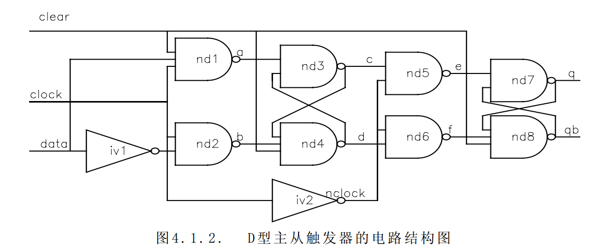
14.用门级结构描述D触发器
module flop(data,clock,clear,q,qb); //定义模块名
		input data,clock,clear;
		output q,qb;
	nand #10 nd1(a,data,clock,clear),  //描述了与非门nd1;data,clock,clear为输入,a为输出,输入输出延时为10个单位时间
		nd2(b,ndata,clock),
		nd4(d,c,b,clear),
		nd5(e,c,nclock),
		nd6(f,d,nclock),
		nd8(qb,q,f,clear);
	nand #9 nd3(c,a,d),
		nd7(q,e,qb);
	not #10 iv1(ndata,data),
			iv2(nclock,clock);
endmodule
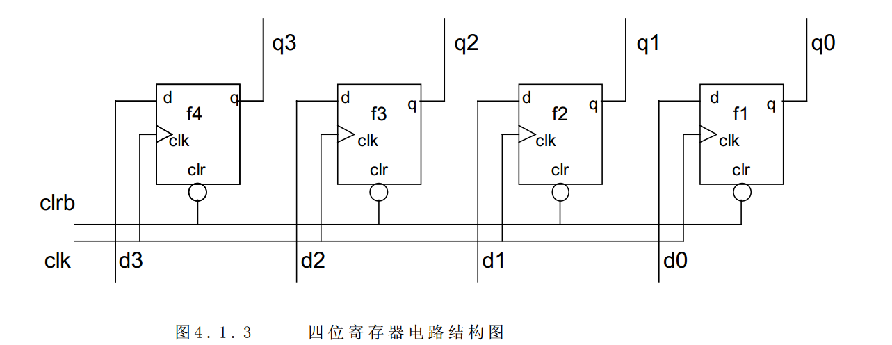
15.引用上例已设计模块flop,用它构成一个四位寄存器
module hardreg(d,clk,clrb,q);
input clk,clrb;
input[3:0] d;
output[3:0] q;
flop f1(d[0],clk,clrb,q[0],),
f2(d[1],clk,clrb,q[1],),
f3(d[2],clk,clrb,q[2],),
f4(d[3],clk,clrb,q[3],);
endmodule
16.4位加法器
module add_4(X,Y,sum,C);
input[3:0] X,Y;
output [3:0] sum;
output C;
assign {C,Sum}=X+Y;
endmodule
17.四位乘法器
module mult_4( X, Y, Product);
input [3 : 0] X, Y;
output [7 : 0] Product;
assign Product = X * Y;
endmodule
18.八位乘法器
module mult_8( X, Y, Product);
input [7 : 0] X, Y;
output [15 : 0] Product;
assign Product = X * Y;
endmodule
19.比较器
module compare_n ( X, Y, XGY, XSY, XEY);
input [width-1:0] X, Y;
output XGY, XSY, XEY;
reg XGY, XSY, XEY;
parameter width = 8;
always @ ( X or Y ) // 每当 X 或 Y 变化时
begin
if ( X = = Y )
XEY = 1; // 设置 X 等于 Y 的信号为 1
else XEY = 0;
if (X > Y)
XGY = 1; // 设置 X 大于 Y 的信号为 1
else XGY = 0;
if (X < Y)
XSY = 1; // 设置 X 小于 Y 的信号为 1
else XSY = 0;
end
endmodule
19.多路器
module Mux_8( addr,in1, in2, in3, in4, in5, in6, in7, in8, Mout, nCS);
input [2:0] addr;
input [width-1] in1, in2, in3, in4, in5, in6, in7, in8;
output [width-1] Mout;
parameter width = 8;
always @ (addr or in1 or in2 or in3 or in4 or in5 or in6 or in7 or in8)
begin
if (!ncs)
case(addr)
3’b000: Mout = in1;
3’b001: Mout = in2;
3’b010: Mout = in3;
3’b011: Mout = in4;
3’b100: Mout = in5;
3’b101: Mout = in6;
3’b110: Mout = in7;
3’b111: Mout = in8;
endcase
else
Mout = 0;
end
endmodule
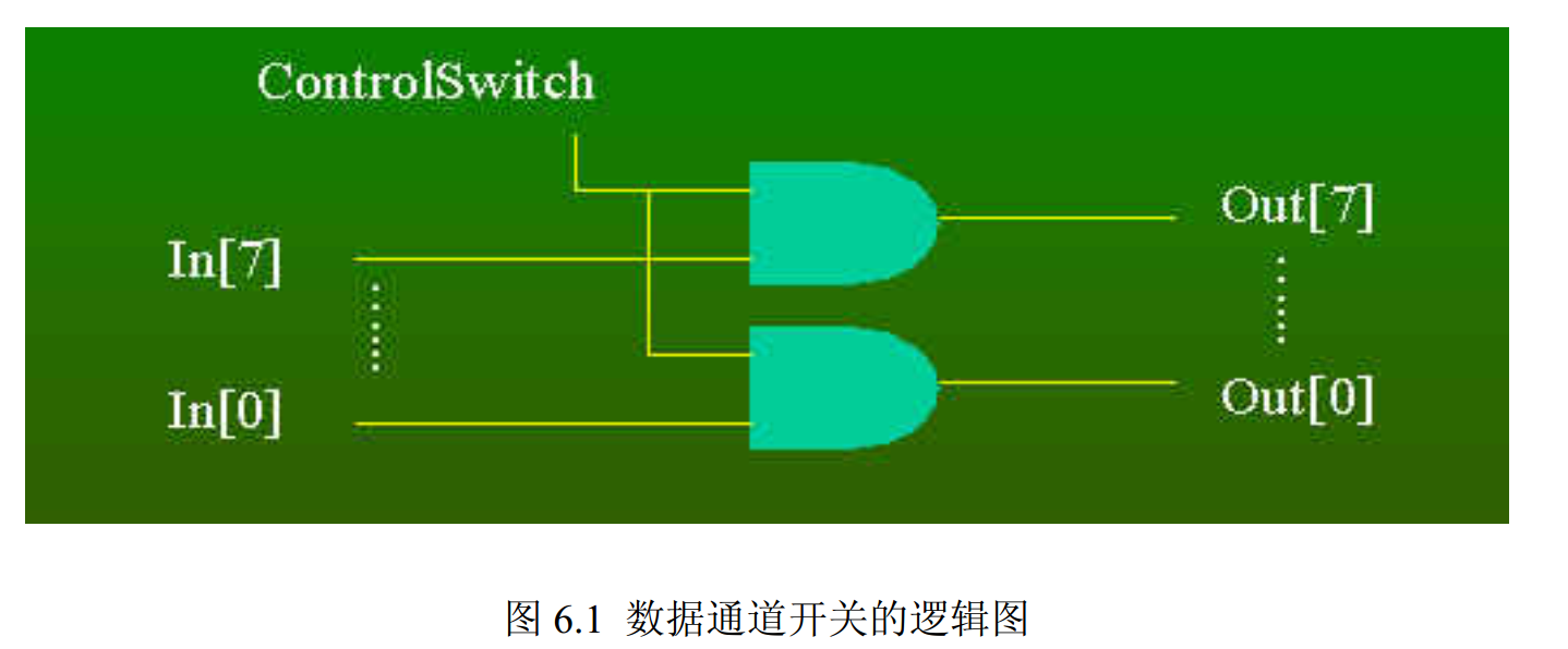
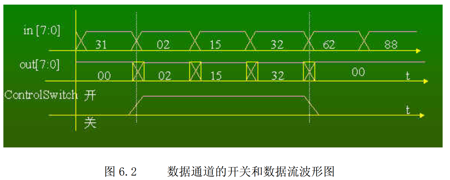
20.组合逻辑举例:一个八位数据通路控制器
`define ON 1 ‘b 1
`define OFF 1 ‘b 0
wire ControlSwitch;
wire [7:0] Out, In;
assign Out = (ControlSwith = = `ON) ? In : 8 ‘h00;
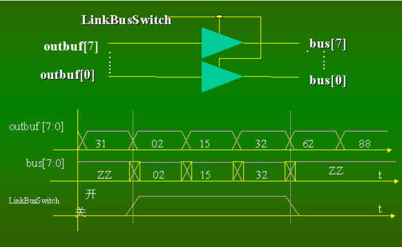
21.一个八位三态数据通路控制器
`define ON 1 ‘b 1
`define OFF 1 ‘b 0
wire LinkBusSwitch;
wire [7:0] outbuf;
inout [7:0] bus;
assign bus = (LinkBusSwitch== `ON) ? outbuf : 8 ‘hzz
22.宇宙飞船控制器的状态机
module statmch1(launch_shuttle,lan_shuttle,start_countdown,
start_trip_meter,clk,
all_systems_go,just_launched,is_landed,cnt,abort_mission);
output launch_shuttle, land_shuttle, start_countdown,
start_trip_meter;
input clk, just_launched, is_landed, abort_mission,
all_systems_go;
input [3:0] cnt;
reg launch_shuttle, land_shuttle, start_countdown,
start_trip_meter;
//设置独热码状态的参数
parameter HOLD=5'h1, SEQUENCE=5'h2, LAUNCH=5'h4;
parameter ON_MISSION=5'h8, LAND=5'h10;
reg [4:0] present_state, next_state;
always@(negedge clk or posedge abort_mission)
	begin
/****把输出设置成某个缺省值,在下面的case语句中
就不必再设置输出的缺省值*******/
{launch_shuttle, land_shuttle, start_trip_meter, start_countdown} =4'b0;
/*检查异步reset的值即abort_mission的值*/
if(abort_mission)
next_state=LAND;
else
begin // if-else-begin
/*如果reset为零,把next_state赋值为present_state*/
next_state = present_state;
/*根据 present_state 和输入信号,设置 next_state
和输出output*/
case ( present_state )
HOLD: if(all_systems_go)
begin
next_state = SEQUENCE;
start_countdown = 1;
end
SEQUENCE: if(cnt==0)
next_state = LAUNCH;
LAUNCH:
begin
next_state = ON_MISSION;
launch_shuttle = 1;
end
ON_MISSION:
//取消使命前,一直留在使命状态
if(just_launched)
start_trip_meter = 1;
LAND: if(is_landed)
next_state = HOLD;
else land_shuttle = 1;
/*把缺省状态设置为'bx(无关)或某种已知状态,使其
在做仿真时,在复位前就与实际情况相一致*/
default: next_state = 'bx;
endcase
end // end of if-else
/*把当前状态变量设置为下一状态,待下一有效时钟沿来到
时当前状态变量已设置了正确的状态值*/
present_state = next_state;
end //end of always
endmodule
最后
以上就是耍酷电源最近收集整理的关于Verilog HDL学习笔记的全部内容,更多相关Verilog内容请搜索靠谱客的其他文章。


发表评论 取消回复