ESP-01S arduino
- ESP-01S引脚功能简介
- arduino ESP-01S 配置
- 测试Demo
ESP-01S 一般可以直接使用原厂的固件 进行AT指令通信控制,如果有兴趣制作一个简单一点的类似玩具,比如智能开关,ESP-01S就是最好的选择,直接使用ESP-01S作为MCU,相当舒适。简单记录一些ESP-01S的管脚功能与使用过程。
ESP-01S引脚功能简介
ESP-01S 模组共接出 8 个接口,如管脚示意图:
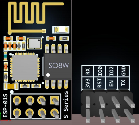
引脚功能图:
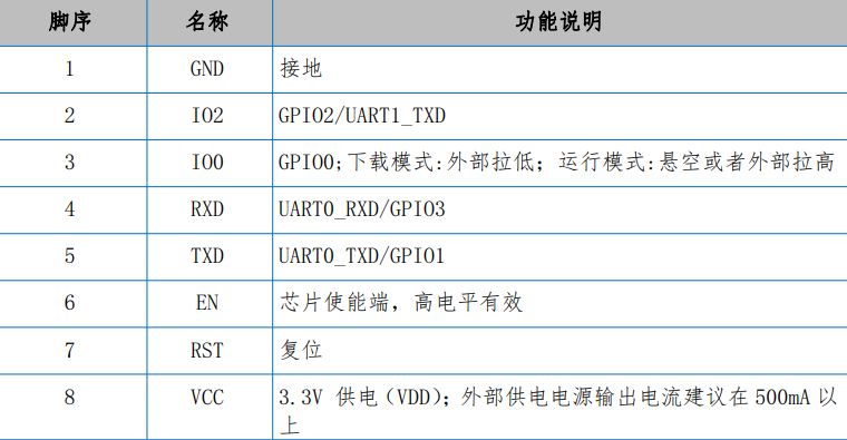
GPIO0 被下载电路所占用,不建议单独使用这个IO口,GPIO2 被内置LED灯所使用,那样可以单独使用的端口就只有3个分别为GPIO1(UART0_TXD)、GPIO2、GPIO3(UART0_RXD)。
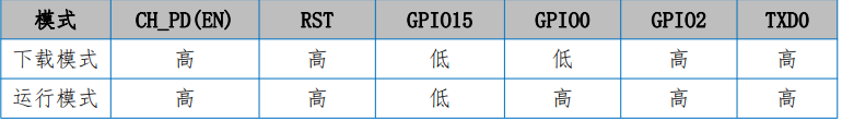
下载与启动模式:
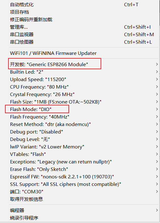
arduino ESP-01S 配置
测试Demo
一个简单LED闪烁,可以使用的端口有3个,可以使用ESP8266的一些程序直接移植过来就可以使用。
/*
  Note that this sketch uses LED_BUILTIN to find the pin with the internal LED
  GPIO2   LED
*/

void setup() {
   Serial.begin(115200);
  pinMode(LED_BUILTIN, OUTPUT);     // Initialize the LED_BUILTIN pin as an output
}

// the loop function runs over and over again forever
void loop() {
  Serial.println("LED LOW");
  digitalWrite(LED_BUILTIN, LOW);   // Turn the LED on (Note that LOW is the voltage level
  // but actually the LED is on; this is because
  // it is active low on the ESP-01)
  delay(1000);                      // Wait for a second
  Serial.println("LED HIGH");
  digitalWrite(LED_BUILTIN, HIGH);  // Turn the LED off by making the voltage HIGH
  delay(1000);                      // Wait for two seconds (to demonstrate the active low LED)
}
最后
以上就是喜悦树叶最近收集整理的关于ESP-01S使用Arduino编写ESP-01S引脚功能简介arduino ESP-01S 配置测试Demo的全部内容,更多相关ESP-01S使用Arduino编写ESP-01S引脚功能简介arduino内容请搜索靠谱客的其他文章。
本图文内容来源于网友提供,作为学习参考使用,或来自网络收集整理,版权属于原作者所有。


发表评论 取消回复