verilog的设计文件:
module BPSK(
		input clk,
		input [7:0] indata,
		output reg [15 : 0] myout,
		output wire [15:0] fir_out_my
		);
wire m_axis_data_tvalid;

wire s_axis_data_tready;
reg [9 : 0] addra = 0;
wire [19 : 0] outdata;

fir_compiler_0 fir_compiler_0 (
	.aclk(clk),                               // input wire aclk           输入时钟
	.s_axis_data_tvalid(1),  // input wire s_axis_data_tvalid
	.s_axis_data_tready(s_axis_data_tready),  // output wire s_axis_data_tready
	.s_axis_data_tdata(indata),    // input wire [7 : 0] s_axis_data_tdata(输入数据) 8位
	.m_axis_data_tvalid(m_axis_data_tvalid),  // output wire m_axis_data_tvalid
	.m_axis_data_tdata(fir_out_my)    // output wire [15 : 0] fir_out_my(输出数据16位)
);
/*
aresetn:复位引脚,低电平复位FIR IP核;
aclk:时钟引脚,工程中输入500MHz时钟信号;
s_axis_data_tdata:输入采样数据;
s_axis_data_tready:1 表示IP核准备好接收采样数据;
s_axis_data_tvalid:1 表示s_axis_data_tdata输入的采样数据有效;
fir_out_my:输出滤波后的数据;
m_axis_data_tvalid:1 表示fir_out_my输出的数据有效。

*/
//生成正弦波
wire [9 : 0] sin_out;

blk_mem_gen_0 blk_mem_gen_0 (
		.clka(clk),    // input wire clka
		.ena(1),      // input wire ena
		.addra(addra),  // input wire [9 : 0] addra
		.douta(sin_out)  // output wire [9 : 0]
);
//乘法器
sinmult sinmult (
	.CLK(clk),  // input wire CLK
	.A(fir_out_my),      // input wire [9 : 0] A
	.B(sin_out),      // input wire [9 : 0] B
	.P(outdata)      // output wire [19 : 0] P
);
always@(posedge clk)begin
				addra 	<= 	addra		 +	 256;
				myout		<=	outdata[17:2];
end

endmodule
tb文件:
`timescale 1ns / 1ps
// fclk = 500MHZ

module tb();

    reg [7:0] indata = 7'b0;
    wire [15 : 0] myout;
    reg clk;
    reg [5-1:0] sps = 5'd0;
     wire [15:0] fir_out_my;
    reg  	[1-1:0]	 DataMem [0:8000-1];
    reg 	[13-1:0] AddrMem = 13'd0;   //8064
BPSK BPSK(
    .clk        (   clk     ),
    .indata     (   indata  ),
    .myout       (   myout ),
    .fir_out_my(fir_out_my)
);

always #1 clk = ~ clk;
integer dout_file1;
initial begin
	clk = 0;

	$readmemh("../../../../SimData/CSV/FrmBin.txt", DataMem);

	dout_file1=$fopen("../../../../SimData/CSV/rcos.txt");    //打开所创建的文件

	  if(dout_file1 == 0)begin
				$display ("can not open the file!");    //创建文件失败,显示can not open the file!
				$stop;
	   end
end

    always@(posedge clk)begin
        //$fdisplay(dout_file1,"%d",$signed(myout));

        $fdisplay(dout_file1,"%d",  $signed(fir_out_my));

        if(sps==0)begin
            indata  <=  {5'd0,DataMem[AddrMem],1'b1};
            sps     <=  sps + 1;
            AddrMem <= AddrMem + 1;
        end
        else if(sps<15)begin
            indata  <=  7'd0;
            sps     <=  sps + 1;

        end
        else if(sps == 15)begin
            indata  <= 7'd0;
            sps     <= 0;

        end
    end
endmodule
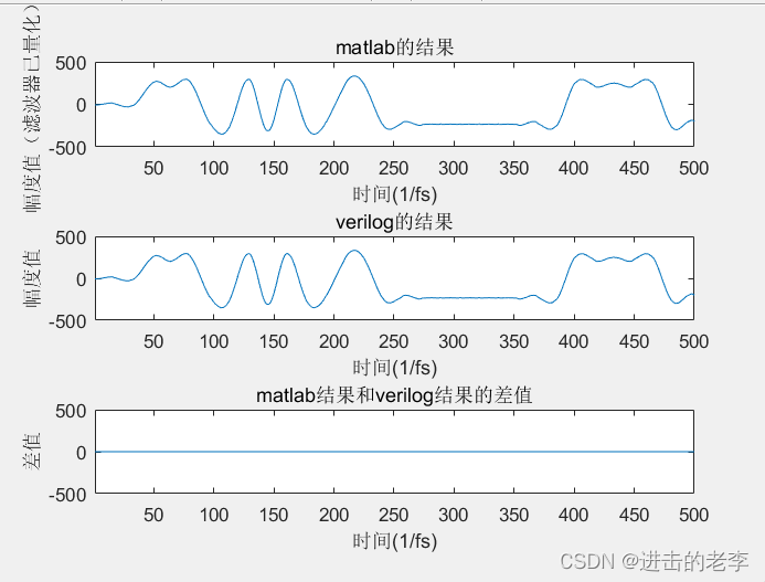
verilog的fir实现的根升余弦滤波器的输出与matlab的根升余弦滤波器输出的代码:
clc;
close all;
clear;

b = rcosdesign(0.35,6,16,'sqrt');
bb = round(255.*b./max(b));
fs = 500*10e6;
fc = fs/4;

msg_source = load('D:vivado_documentproject_3SimDataCSVFrmBin.txt');

bipolar_msg_source = -2.*msg_source'+1;%0,1映射为1,-1
rcos_msg_source = upfirdn(bipolar_msg_source,bb,16);
n = 1:length(rcos_msg_source);

verilog_seq = load('D:vivado_documentproject_3SimDataCSVrcos.txt');

xmin = 1;
xmax = 500;
ymax = 500;
delay = 59;
xend = 500;%为了确保matlab的结果和verilog的结果长度一致能够作差
verilog_seq_delay = verilog_seq(delay:end)';

figure;
subplot(3,1,1)
plot(rcos_msg_source);%%%
axis([xmin xmax -ymax ymax]);
title('matlab的结果')
xlabel('时间(1/fs)');
ylabel('幅度值(滤波器已量化)');

subplot(3,1,2)
plot(verilog_seq_delay);%%%
axis([xmin xmax -ymax ymax]);
title('verilog的结果')
xlabel('时间(1/fs)');
ylabel('幅度值');

subplot(3,1,3)
y=rcos_msg_source(1:xend) - verilog_seq_delay(1:xend);

plot(y);
axis([xmin xmax -ymax ymax]);
title('matlab结果和verilog结果的差值');
xlabel('时间(1/fs)');
ylabel('差值');
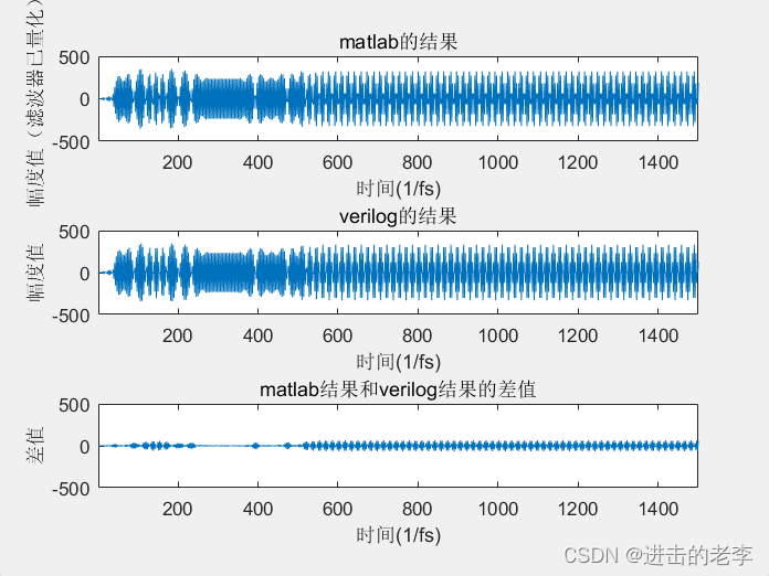
接下来是最终的发送波形的对比
clc;
close all;
clear;

b = rcosdesign(0.35,6,16,'sqrt');
bb = round(255.*b./max(b));
fs = 500*10e6;
fc = fs/4;

msg_source = load('D:vivado_documentproject_3SimDataCSVFrmBin.txt');

bipolar_msg_source = -2.*msg_source'+1;%0,1映射为1,-1,因为verilog就是这么弄得
rcos_msg_source = upfirdn(bipolar_msg_source,bb,16);
n = 1:length(rcos_msg_source);
rcos_msg_source_carrier = rcos_msg_source.*cos(2*pi*fc.*n/fs);
%存放verilog载波乘法器的输出的地方
verilog_seq = load('D:vivado_documentproject_3SimDataCSVmyFrmBin.txt');


xmin = 1;
xmax = 1500;
ymax = 500;
delay = 62;
xend = 1500;%为了确保matlab的结果和verilog的结果长度一致能够作差
verilog_seq_delay = verilog_seq(delay:end)'/64;

figure;
subplot(3,1,1)
plot(rcos_msg_source_carrier);%%%
axis([xmin xmax -ymax ymax]);
title('matlab的结果')
xlabel('时间(1/fs)');
ylabel('幅度值(滤波器已量化)');

subplot(3,1,2)
plot(verilog_seq_delay);%%%
axis([xmin xmax -ymax ymax]);
title('verilog的结果')
xlabel('时间(1/fs)');
ylabel('幅度值');

subplot(3,1,3)
y=rcos_msg_source_carrier(1:xend) - verilog_seq_delay(1:xend);

plot(y);
axis([xmin xmax -ymax ymax]);
title('matlab结果和verilog结果的差值');
xlabel('时间(1/fs)');
ylabel('差值');
结果如下:
最后
以上就是陶醉面包最近收集整理的关于verilog实现bpsk的发送并与matlab的bpsk仿真进行对比的全部内容,更多相关verilog实现bpsk内容请搜索靠谱客的其他文章。
本图文内容来源于网友提供,作为学习参考使用,或来自网络收集整理,版权属于原作者所有。


发表评论 取消回复