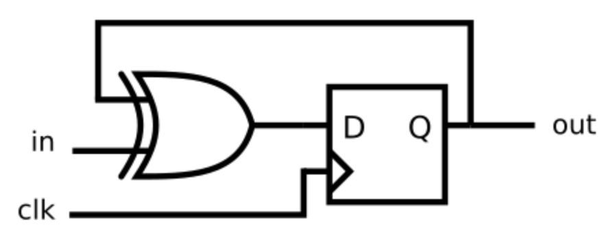
需要实现的电路
代码
代码1
module top_module (
    input clk,
    input in,
    output reg out);
    reg d;
    always@(*)
        d = in^out;
    always@(posedge clk)begin
    	out <= d;
    end

endmodule
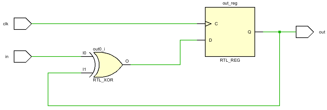
生成电路
代码2
module top_module (
    input clk,
    input in,
    output reg out);
    reg d;

    always@(posedge clk)begin
        d = in^out;                  // 注意这里是阻塞赋值
    	out <= d;
    end

endmodule
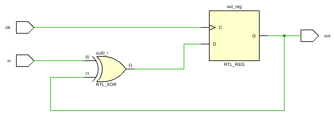
生成电路
代码3
module top_module (
    input clk,
    input in,
    output reg out);
    reg d;

    always@(posedge clk)begin
        d <= in^out;       // 注意这里为非阻塞赋值
    	out <= d;
    end

endmodule
生成电路
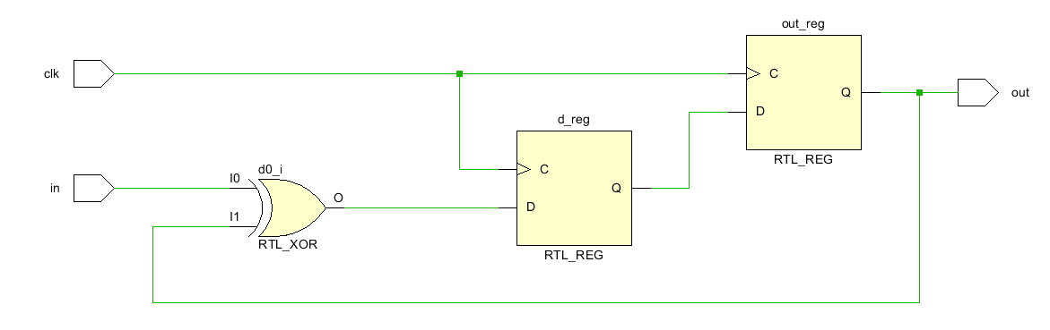
由于采用非阻塞赋值,导致,当前拍(时钟上升沿)得到的d,需要在下一拍才能传递到out处,因此综合出来的电路会多出一个Reg。
总结
组合电路部分最好和时序电路放在不同的always块中实现,能够极大程度避免综合出的电路和设想之间出现差异。还有一点感悟就是:如何利用手头现有的模块实现现有功能。
最后
以上就是迅速酸奶最近收集整理的关于将组合逻辑放到时序逻辑中的全部内容,更多相关将组合逻辑放到时序逻辑中内容请搜索靠谱客的其他文章。
本图文内容来源于网友提供,作为学习参考使用,或来自网络收集整理,版权属于原作者所有。


发表评论 取消回复