目录
定制过程
准备进入定制页面
第一页
Clocking features
第二页
第三页
Selecting Optional Ports
第四页
第五页
第六页
定制过程
准备进入定制页面
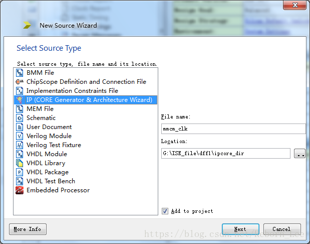
首先通过ISE建立一个工程,然后添加New Source,选择IP核生成选项:
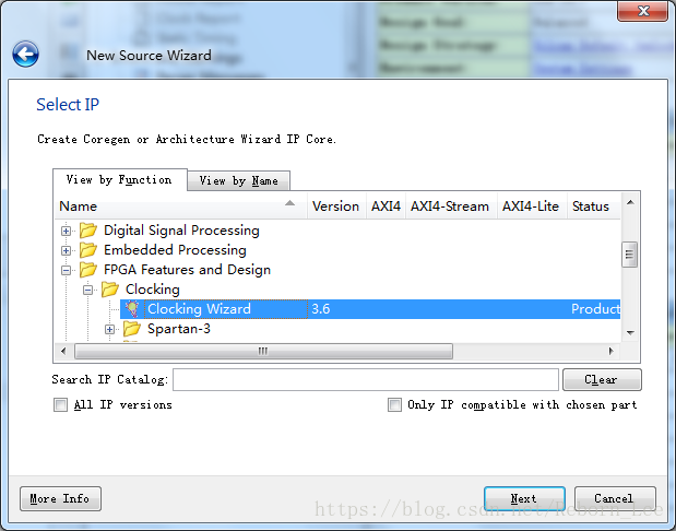
进入IP核选择页面,选择FPGA Features and Design下的Clocking,展开有一个Clocking Wizard:
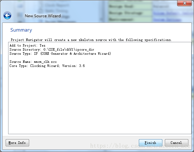
点击Next,进入总结页面:
第一页
Finish之后,进入IP核定制与生成页面,根据Clocking Wizard正式开始定制你的IP核(没有选择Spread Spectrum):
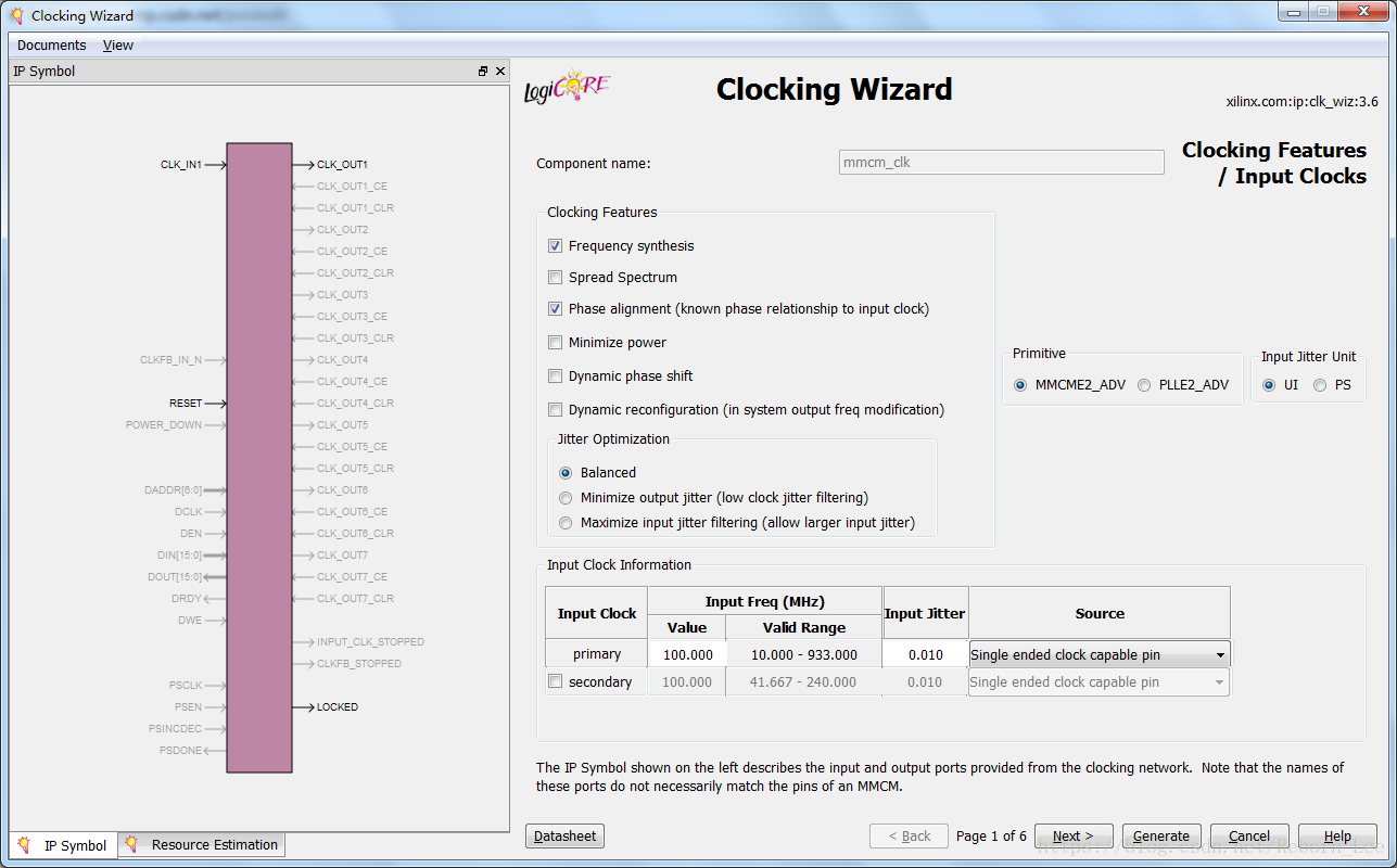
第一个页面中有个时钟原语选择的选项(Primitive),这里选择MMCM,意思是定制一个混合模式时钟管理器(MMCM)的IP核,如果选择了PLL,那么定制的IP核就是一个PLL IP核了。
Clocking features
下面再介绍一下上图中的一些Clocking features:
The available clocking features are shown for the selected target device. You can select as many features as desired; however, some features consume additional resources, and some can result in increased power consumption. Additionally, certain combinations of features are not allowed. The GUI will either dim out or hide features which are unavailable.
For example, the Dynamic Reconfiguration Port checkbox is not available for selection in the case of DCM and PLL_BASE as both of these do not support this feature.
Clocking features include:
• Frequency synthesis. This feature allows output clocks to have different frequencies than the active input clock.
• Spread Spectrum (SS). This feature provides modulated output clocks which reduces the spectral density of the electromagnetic interference (EMI) generated by electronic devices. This feature is available only for MMCME2 primitive.
• Phase alignment. This feature allows the output clock to be phase locked to a reference, such as the input clock pin for a device.• Minimize power. This features minimizes the amount of power needed for the primitive at the possible expense of frequency, phase offset, or duty cycle accuracy.
• Dynamic phase shift. This feature allows you to change the phase relationship on the output clocks.• Dynamic reconfiguration. This feature allows you to change the programming of the primitive after device configuration. When this option is chosen, the clocking wizard uses only integer values for M, D and CLKOUT[0:6]_DIVIDE.
• Balanced. Selecting Balanced results in the software choosing the correct BANDWIDTH for jitter optimization.
• Minimize output jitter. This feature minimizes the jitter on the output clocks, but at the expense of power and possibly output clock phase error. This feature is not available with ‘Maximize input jitter filtering’.
• Maximize input jitter filtering. This feature allows for larger input jitter on the input clocks, but can negatively impact the jitter on the output clocks. This feature is not available with ‘Minimize output jitter’.
英文是数据手册上的介绍,已经很清晰了,如果看得懂就看,看不懂就看我下面的解释;
上面的那个时钟向导GUI界面上显示的都是一些可用的时钟功能,这里选择的器件是Virtex7,如果你选择的是Spartan6的话,就不会有MMCM这个原语出现,所以GUI界面上显示的都是能用的。
这些时钟功能你可以选择多个你需要的,但需要注意的是,一些时钟功能消耗额外的资源,有的还能导致功耗增加。另外,还有一些功能组合是不允许的,不能用的时候,界面会把不允许组合的一些功能隐藏或者暗下来。例如选择了Spread Spectrum (SS),就不能选Dynamic phase shift、Minimize power等。
下面正式介绍这些时钟特征:
• Frequency synthesis:该功能让你的输出时钟可以有多个不同于输入时钟的频率;
• Spread Spectrum (SS):此功能提供调制输出时钟,可降低电子设备产生的电磁干扰(EMI)的频谱密度。 此功能仅适用于MMCME2原语。
• Phase alignment:此功能允许输出时钟相位锁定到一个参考值,例如器件的输入时钟引脚。
• Minimize power:该功能以可能的频率,相位偏移或占空比精度为代价,最小化了原语所需的功率量。
• Dynamic phase shift:该功能可以让你改变输出时钟之间的相位关系。
• Dynamic reconfiguration:此功能允许您在设备配置后更改基元的编程。 选择此选项时,时钟向导仅使用M,D和CLKOUT [0:6] _DIVIDE的整数值。
• Balanced:选择Balanced会导致软件选择正确的BANDWIDTH进行抖动优化。
• Minimize output jitter:此功能可最大限度地减少输出时钟的抖动,但会以功耗和可能的输出时钟相位误差为代价。 “最大化输入抖动滤波”不提供此功能。
• Maximize input jitter filtering:此功能允许输入时钟上的输入抖动较大,但会对输出时钟上的抖动产生负面影响。 “最小化输出抖动”不提供此功能。
上图为没有选择Spread Spectrum (SS)这个功能的GUI界面,下图给出选择了这个功能的界面:
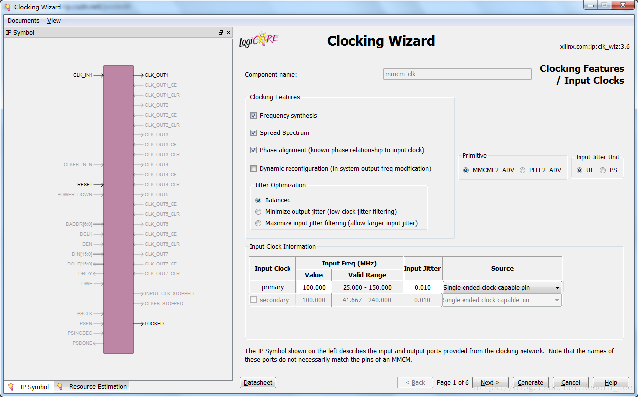
比较这两张图可以发现,选择了Spread Spectrum这个功能后,输入频率范围变成了25MHz到150MHz,没有选择时的频率范围为:10MHz-933MHz。
实际情况,根据具体需求来选择你需要的时钟功能。
此外,通过第一个GUI界面,我们还可以看到,可以选择第二(辅助)输入时钟(Secondary Input Clock),这是什么情况呢?
下面是用户手册的原话:
For Virtex-6 and 7 series FPGAs, you can enable an additional input clock. Select the box next to the secondary input clock to enable the additional input clock. Depending on the frequency of the secondary input clock, this can cause a less ideal network to be created than might be possible if just the primary input clock was present (more output jitter, higher power, etc.)
Enter the frequency and peak-to-peak period (cycle) jitter for the input clocks. The wizard then uses this information to create the clocking network. Additionally, a UCF (user constraint file) is created using the values entered. For the best calculated clocking parameters, it is best to fully specify the values. For example, for a clock requirement of 33 1/3 MHz, enter 33.333 MHz rather than 33 MHz.
对于Virtex-6和7系列FPGA,您可以启用额外的输入时钟。 选择辅助输入时钟旁边的框以启用其他输入时钟。 根据辅助输入时钟的频率,相比于如果仅存在主输入时钟(更多输出抖动,更高功率等)创建的时钟网络可能不太理想。
输入输入时钟的频率和峰峰值周期(周期)抖动。 然后,向导使用此信息创建时钟网络。 此外,使用输入的值创建UCF(用户约束文件)。 要获得最佳计算时钟参数,最好完全指定值。 例如,对于33 1/3 MHz的时钟要求,输入33.333 MHz而不是33 MHz。
如下图:

有关输入缓冲(buffer)的问题说明:
You can select which buffer type drives your input clock, and this is then instantiated in the provided source code. If your input buffers are located externally, selecting “No buffer” leaves the connection blank.
You can choose the units for input clock jitter by selecting either the UI or PS radio button. The input jitter box accepts the values based on this selection.
您可以选择驱动输入时钟的缓冲区类型,然后它(buffer)将被例化到提供的源代码中。 如果输入缓冲区位于外部,则选择“无缓冲区”会使连接空白。
这里的选择如下图:

您可以通过选择UI或PS单选按钮来选择输入时钟抖动的单位。 输入抖动框接受基于此选择的值。
这里的描述,你可以自己手动选择然后进行比较,例如选择了UI,抖动是这样的:

选择了PS,抖动是这样的:

第二页
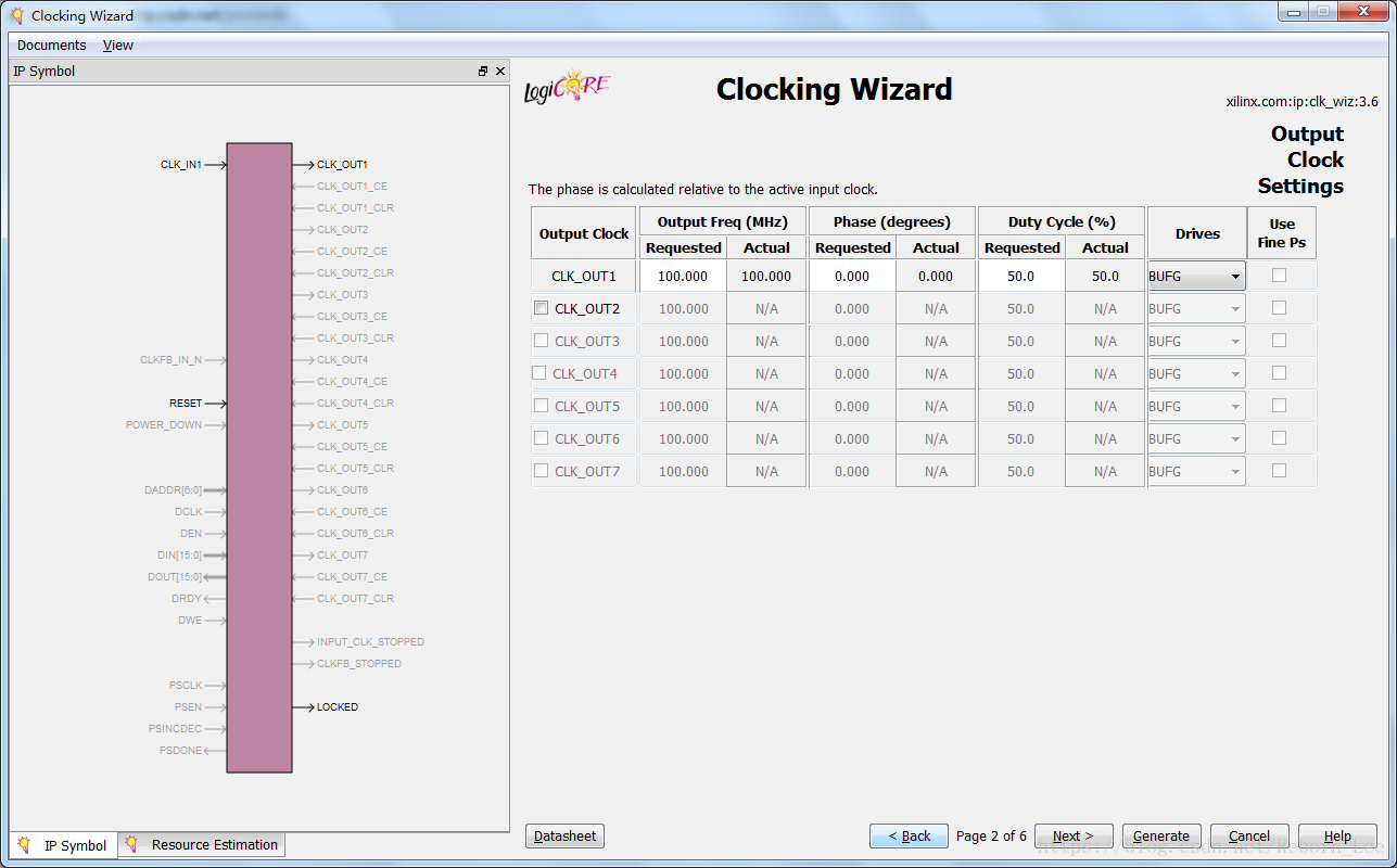
上面说了针对第一个GUI界面上的一些时钟功能,以及输入时钟的配置,下面看看第二个GUI界面,输出时钟的配置问题(注意,这是第一个界面上的Spread Spectrum (SS)功能没有选择的情况下的输出时钟配置界面):
用户手册上给出配置输出时钟的说明:
To enable an output clock, click on the box located next to it. Output clocks must be enabled sequentially. You can specify values for the output clock frequency, phase shift, and duty cycle assuming that the primary input clock is the active input clock. The clocking wizard attempts to derive a clocking network that meets your criteria exactly. In the event that a solution cannot be found, best attempt values are provided and are shown in the actual value column.
Achieving the specified output frequency takes precedence over implementing the specified phase, and phase in turn takes higher precedence in the clock network derivation process than duty cycle.
The precedence of deriving the circuits for the CLK_OUT signals is CLK_OUT1 > CLKOUT2 > CLKOUT3, and so on. Therefore, finding a solution for CLK_OUT1 frequency has a higher priority. Values are recalculated every time an input changes.
要启用输出时钟,请单击旁边的框。 输出时钟必须是 顺序启用。 假设主输入时钟是有效输入时钟,您可以指定输出时钟频率,相移和占空比的值。 时钟向导试图获得完全符合您标准的时钟网络。 如果找不到解决方案,则会提供最佳尝试值并显示在实际值列中。
实现指定的输出频率优先于实现指定的相位,并且相位在时钟网络推导过程中优先于占空比。
导出CLK_OUT信号的电路的优先级是CLK_OUT1> CLKOUT2> CLKOUT3,依此类推。 因此,找到CLK_OUT1频率的解决方案具有更高的优先级。 每次输入更改时都会重新计算值。
很好理解吧,就是输出时钟必须顺序启动,先配置输出时钟1,才能再配置第二个,依次类推。
而且每个输出时钟的频率的优先级大于相位,相位大于占空比。
Because of this, it is best to enter the requirements from top to bottom and left to right. This helps to pinpoint requested values that cannot be supported exactly.
If phase alignment is selected, the phase shift is with respect to the active input clock.If phase alignment is not selected, phase shift is with respect to CLK_OUT1.
Not all primitives allow duty- cycle specification. For example, a DCM_SP is restricted to a 50/50 duty cycle. In the event that duty cycle cannot be specified, the requested column is dimmed.
因此,最好从上到下,从左到右输入要求。 这有助于查明无法准确支持的请求值。
如果选择相位对齐,则相移相对于有效输入时钟。
如果未选择相位对准,则相移相对于CLK_OUT1。
并非所有原语都允许占空比规范。 例如,DCM_SP限制为50/50占空比。 如果无法指定占空比,则请求的列将变暗。
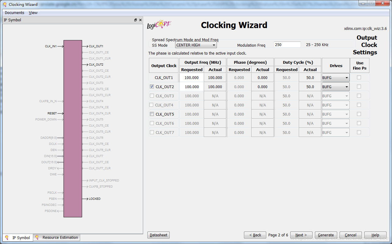
When Spread Spectrum (SS) is selected, CLK_OUT<3> and CLK_OUT<4> are not available.
Divide values of these outputs are used for SS modulation frequency generation.
选择扩频(SS)时,CLK_OUT <3>和CLK_OUT <4>不可用。
这些输出的分频值用于SS调制频率的产生。
如下图为选择了Spread Spectrum (SS)功能后的输出配置页面,正如上面所说,CLK_OUT <3>和CLK_OUT <4>不可用。
这里就提一下算了,后面就不讨论选择Spread Spectrum (SS)功能的情况了,如果你用到了,或实在想了解,那就看用户手册吧,用户手册直接点击界面下方的Datasheet就跳出来了。
第三页
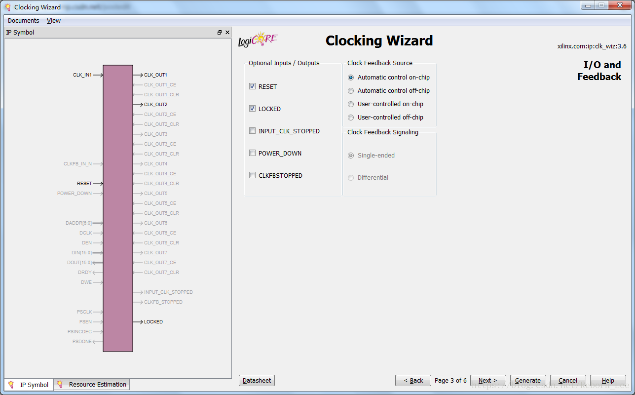
下面介绍第三个GUI界面:
Selecting Optional Ports
All other optional ports that are not handled by selection of specific clocking features are listed under Optional Inputs/Outputs. Click to select the ports that you wish to make visible; inputs that are unused are tied off appropriately, and outputs that are unused are labeled as such in the provided source code.
选择可选端口
选择特定时钟功能未处理的所有其他可选端口列在可选输入/输出下。 单击以选中您希望显示的端口; 未使用的输入被适当地绑定,未使用的输出在提供的源代码中标记为这样。
Choosing Feedback
Feedback selection is only available when phase alignment is selected. When phase alignment is not selected, the output feedback is directly connected to the input feedback.
For designs with phase alignment, choose automatic control on-chip if you want the feedback path to match the insertion delay for CLK_OUT1. You can also select user-controlled feedback if the feedback is in external code. If the path is completely on the FPGA, select on-chip; otherwise, select off-chip.
选择反馈
反馈选择仅在选择相位对齐时可用。 未选择相位对齐时,输出反馈直接连接到输入反馈。
对于具有相位对齐的设计,如果希望反馈路径与CLK_OUT1的插入延迟匹配,请选择片上自动控制。 如果反馈是在外部代码中,您还可以选择用户控制的反馈。 如果路径完全在FPGA上,则选择片内; 否则,选择片外。
For designs that require external feedback and related I/O logic, choose automatic control off-chip feedback. You can choose either single-ended or differential feedback in this mode.
The wizard generates the core logic and logic required to route the feedback signals to the I/O.
对于需要外部反馈和相关I / O逻辑的设计,请选择自动控制片外反馈。 您可以在此模式下选择单端或差分反馈。
该向导生成将反馈信号路由到I / O所需的核心逻辑和逻辑。
第四页
进入下一个页面:Primitive Override Screen
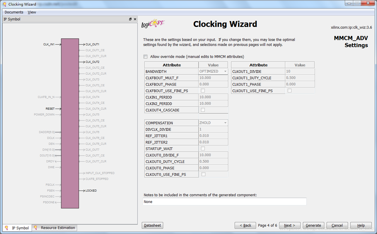
用户手册上这样说:
The clocking wizard selects optimal settings for the parameters of the clocking primitive.
You can override any of these calculated parameters if you wish. By selecting “Allow override mode,” the overridden values are used rather than the calculated values as primitive parameters. The wizard uses the settings as shown on this screen for any timing calculations, and any settings changed here are reflected in the summary pages. It is important to verify that the values you are choosing to override are correct because the wizard implements what you have chosen even if it causes issues with the generated network. Parameters listed are relevant for the physical clocks on the primitive, rather than the logical clocks created in the source code. For example, to modify the settings calculated for the highest priority CLK_OUT1, you actually need to modify CLKOUT0* parameters, and not the CLKOUT1* parameters for a MMCM or PLL.
时钟向导为时钟原语的参数选择最佳设置。
如果您愿意,可以覆盖任何这些计算出的参数。 通过选择“允许覆盖模式”,将使用重写的值而不是计算值作为基本参数。 向导使用此屏幕上显示的设置进行任何计时计算,此处更改的任何设置都会反映在摘要页面中。 验证您选择覆盖的值是否正确非常重要,因为向导会实现您选择的内容,即使它会导致生成的网络出现问题。 列出的参数与基元上的物理时钟相关,而不是源代码中创建的逻辑时钟。 例如,要修改为最高优先级CLK_OUT1计算的设置,实际上需要修改CLKOUT0 *参数,而不是修改MMCM或PLL的CLKOUT1 *参数。
从上面的描述可知,如果你不是老鸟,就不要动这个页面了。
第五页
进入下一个页面:
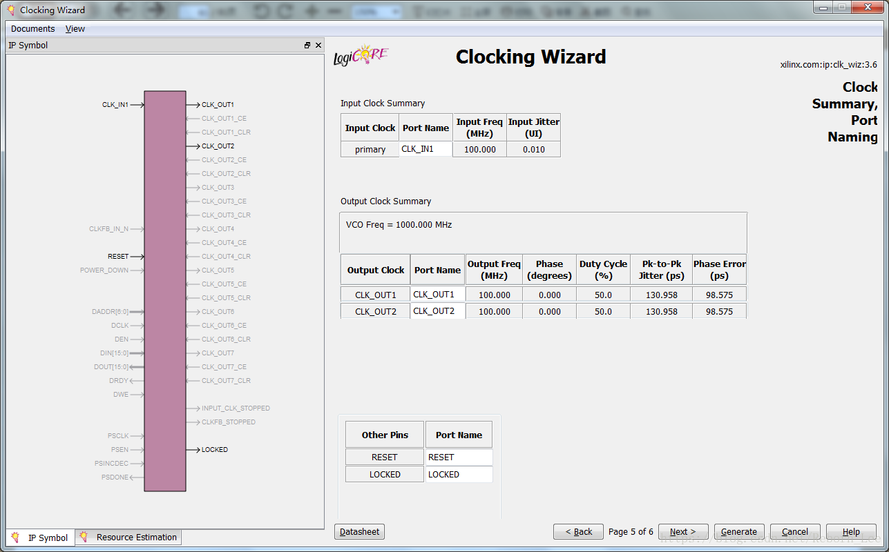
这个页面是一个总结页面,对输入输出时钟的总结,以及端口的命名的总结,你可以根据实际需求修改端口名字,否则就用默认的。
第六页
很简单,进入下一个页面:
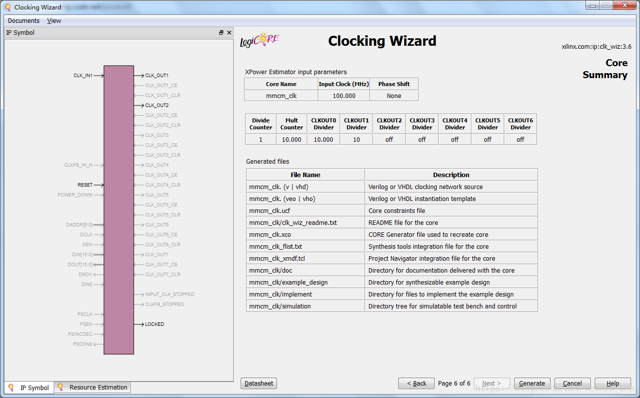
这也是一个总结页面,对IP核进行总结:
Resource Estimate Summary
A resource estimate is provided based on the chosen clocking features.
XPower Estimator Summary
Input parameters to the Xpower tool are provided.
File Report Summary
A summary of created output files is provided. See Chapter 9, Detailed Example Design.
资源估算总结
基于所选择的时钟特征提供资源估计。
XPower Estimator总结
提供了Xpower工具的输入参数。
文件报告总结
提供了已创建的输出文件的总结。
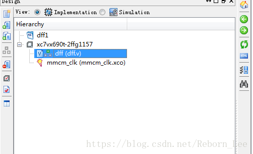
到此为止,一个管理时钟的IP核就生成了。
声明:以上截图都是为了讲解每个页面的功能而进行的直接默认截图,没有根据实际需求来配置功能等。
使用时,请根据自己的需求,自行配置功能参数等。
最后
以上就是孤独鞋垫最近收集整理的关于通过Clocking Wizard定制和生成一个IP核(MMCM)(Virtex7)(ISE版)定制过程的全部内容,更多相关通过Clocking内容请搜索靠谱客的其他文章。


发表评论 取消回复