数字电路设计JK触发器
使用异步输入的PRE和CLR,CLK作为时钟
CLK是上升沿时触发always
module JKchufa(
	input J,
	input K,
    input CLK,
    input _CLR,
    input _PRE,
    output Q,
    output _Q
    );
	 reg Q;


always @(posedge CLK,negedge _PRE,negedge _CLR)
	begin
		if(_PRE==0) Q<=1;
		else if(_CLR==0) Q<=0;
		else case({J,K})
			'b01:Q<=0;
			'b10:Q<=1;
			'b11:Q<=~Q;
			endcase

	end
assign _Q=~Q;

endmodule

//测试文件
module JKtest;

	// Inputs
	reg J;
	reg K;
	reg CLK;
	reg _CLR;
	reg _PRE;

	// Outputs
	wire Q;
	wire _Q;

	// Instantiate the Unit Under Test (UUT)
	JKchufa uut (
		.J(J),
		.K(K),
		.CLK(CLK),
		._CLR(_CLR),
		._PRE(_PRE),
		.Q(Q),
		._Q(_Q)
	);

	initial begin
		// Initialize Inputs
		J = 0;
		K = 0;
		CLK = 0;
		_CLR = 0;
		_PRE = 0;

		// Wait 100 ns for global reset to finish
		#20 _CLR=1;_PRE=0;
		#20 _CLR=0;_PRE=1;
		#20 _CLR=1;_PRE=1;


		// Add stimulus here

	end
   always begin
		#5 CLK=~CLK;
	end
	always begin
		#10 {J,K}={J,K}+1;
	end
endmodule
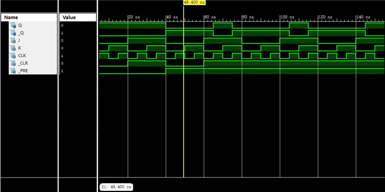
仿真波形
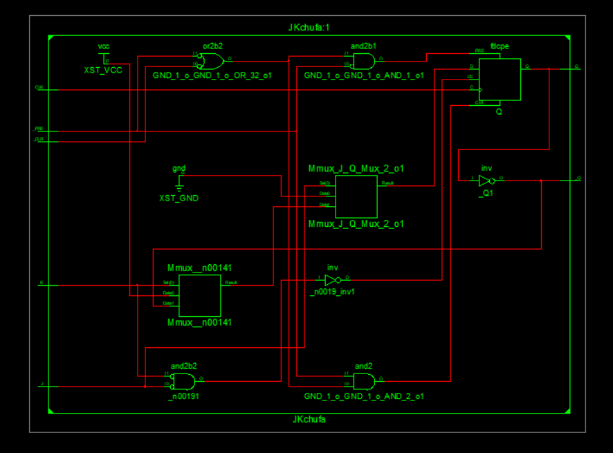
RTL电路图
本代码采用ISE14.7仿真
最后
以上就是忧心期待最近收集整理的关于数字电路设计JK触发器的全部内容,更多相关数字电路设计JK触发器内容请搜索靠谱客的其他文章。
本图文内容来源于网友提供,作为学习参考使用,或来自网络收集整理,版权属于原作者所有。


发表评论 取消回复