Chopper-Fed DC Motor Drive
This example shows a Chopper-Fed DC Motor Drive.
Description
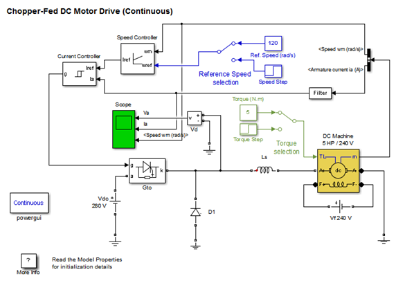
The DC motor is fed by the DC source through a chopper which consists of GTO thyristor and free-wheeling diode D1. The motor drives a mechanical load characterized by inertia J, friction coeficient B, and load torque TL.
The hysteresis current controller compares the sensed current with the reference and generates the trigger signal for the GTO thyristor to force the motor current to follow the reference. The speed control loop uses a proportional-integral controller which produces the reference for the current loop. Current and Voltage Measurement blocks provide signals for visualization purpose.
Simulation
Motor starting
Start the simulation. Observe the motor current, voltage, and speed during the starting on the scope. At the end of the simulation time (1.5 s), the system has reached its steady-state.
Response to a change in reference speed and load torque
The initial conditions state vector ‘xInitial’ to start with wm = 120 rad/s and TL = 5 N.m has been saved in the ‘power_dcdrive_init.mat’ file. This file is automatically loaded in your workspace when you start the simulation (see Model Properties). In order to use these initial conditions you have to enable them. Check the Simulation/Configuration Parameters menu , then select “Data Import/Export” and check “Initial state”.
Now, double click the two Manual Switch blocks to switch from the constant "Ref. Speed (rad/s) " and “Torque (N.m)” blocks to the Step blocks. (Reference speed wref changed from 120 to 160 rad/s at t = 0.4 s and load torque changed from 5 to 25 N.m at t= 1.2s). Restart the simulation and observe the drive response to successive changes in speed reference and load torque.
在此基础上修改测试
Chopper-Fed DC Motor Drive (Discrete)
his example shows a Chopper-Fed DC Motor Drive.
H. LeHuy (Universite Laval, Quebec) and G. Sybille (Hydro-Quebec)
On this page…
Description
Simulation
Description
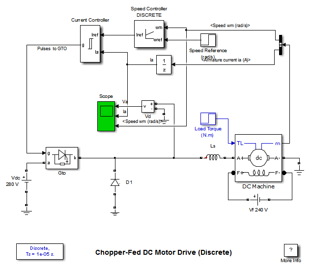
A DC motor is fed by a DC source through a chopper which consists of GTO thyristor and a free-wheeling diode.
The motor drives a mechanical load characterized by inertia J, friction coeficient B, and load torque TL. The motor uses the discrete DC machine provided in the Machines library.
The hysteresis current controller compares the sensed current with the reference and generates the trigger signal for the GTO thyristor to force the motor current to follow the reference. The speed control loop uses a proportional-integral controller which produces the reference for the current loop.
Simulation
Start the simulation and observe the motor voltage (Va), current (Ia) and speed (wm) on the scope. The following observations can be made:
0 < t < 0.8 s: Starting and Steady State Operation
During this period, the load torque is TL = 5.N.m and the motor reaches the reference speed (wref = 120 rad/s) given to the speed controller . The initial values of reference torque and speed are set in the two Step blocks connected to the TL torque input of the motor. Notice that during the motor starting the current is maintained to 30 A, according to the current limit set in the speed regulator. Zoom in the motor current Ia in steady state. Observe the current triangular waveshape varying between 5 A and 7 A, corresponding to the specified hysteresis of 2 A. The commutation frequency is approximately 1.5 kHz.
t = 0.8 s: Reference Speed Step
The reference speed is increased from 120 rad/s to 160 rad/s. The speed controller regulates the speed in approximately 0.25 s, and the average current stabilizes at 6.6 A. During the transient period, current is still limited at 30 A.
t = 1.5 s: Load Torque Step
The load torque is suddenly increased from 5 N.m to 25 N.m. The current increases to 23 A, while speed is maintained at the 160 rad/s set point.
1、速度给定模块
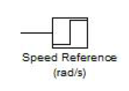
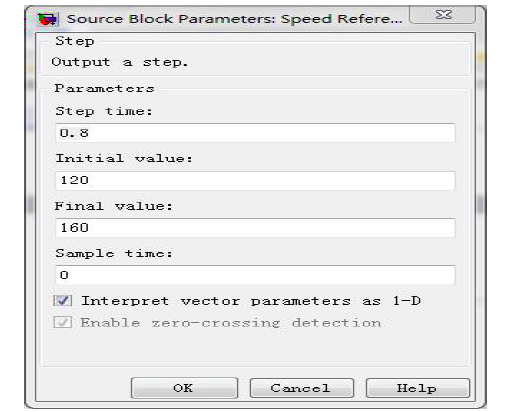
如图4 所示为速度给定模块,为一阶跃信号,由表1 的模块参数表可知速度给定信号的阶跃时间Step time 为0.8s,阶跃信号初始值Initial value 为120rad/s,稳定值Final value 为160rad/s。该模块的功能为产生一个阶跃的速度给定信号wef 输入到速度调节器中。
2、速度调节器
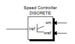
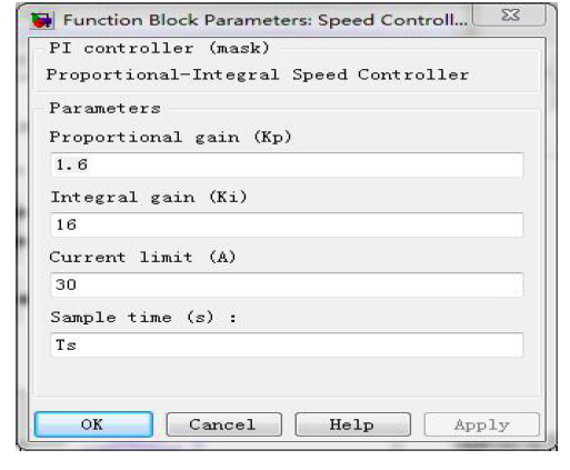
图5 为速度调节器模块,是一个PI 调节器,输入信号为速度给定信号wef与速度反馈信号wm,输出信号Iref 作为电流调节器的电流给定信号。通表2 的模块参数表可知该PI 调节器的比例系数kp=1.6,积分系数ki=16,最大输出限幅值Current limit 为30A。该模块的功能为通过对电机速度的闭环控制输出电流调节器的给定信号Iref。
3、电流调节器
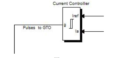
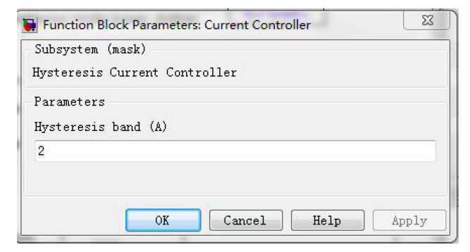
图6 为电流调节器模块,是一个滞环调节器,输入信号为电流给定信号Iref与电流反馈信号Ia,输出信号为GTO 的通断开关信号。通过表3 的模块参数表可知,滞环宽度Hysteresis Band 为2A,当两个电流输入量之差超过2A 时,输出GTO 开通或关断信号对电路进行调节。该模块的功能为产生GTO 的门级信号控制其导通或关断,从而调整电枢电流在允许的范围内。
4、PWM 触发模块
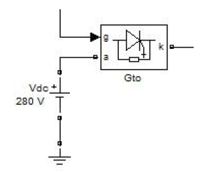
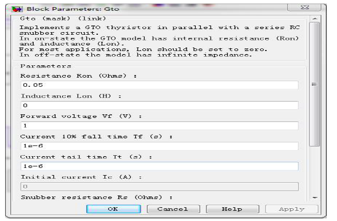
图7 为PWM 触发模块,a 处接280V 的直流电源,输入信号即GTO 的门级信号g 为电流调节器的输出信号,当g 为高电平时,GTO 导通,电源电压加在电枢两端,g 为低电平时,GTO 关断,电枢电压为零。通过表4 的模块表参数可知晶闸管元件内电阻Resistance Ron 为0.05Ω,晶闸管元件内电感Inductance Lon为0H,晶闸管元件的正向管压降Forward voltage Vf 为1V,电流下降到10%的时间Current 10% fall time 为1us,电流拖尾时间Current tail time 为1us,初始电流
Initial current Ic 为零。该模块的功能为通过GTO 的关断与开通输出PWM 波,从而改变电枢两端电压,控制电枢电流在合适的范围内。
5、转矩给定模块
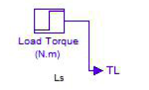
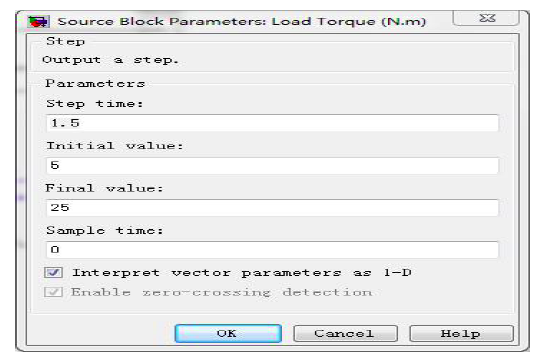
图8 为直流电机的转矩给定模块,为一阶跃信号,由表5 的模块参数表可知转矩给定信号的阶跃时间Step time 为1.5s,阶跃信号初始值Initial value 为5N·m,稳定值Final value 为25N·m。该模块的功能为产生一个阶跃的z 转矩给定信号TL 作为直流电机的负载转矩。
6、直流电机模块
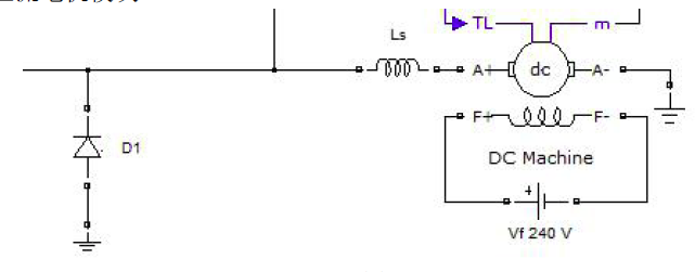
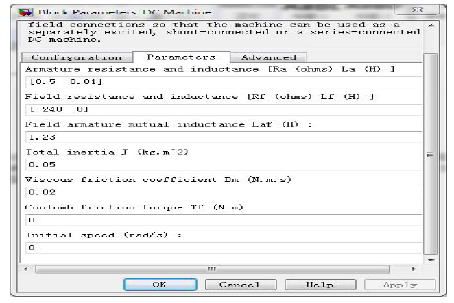
图9 为直流电机模块,直流电机电枢两端反并联二极管D1 作为续流回路,电枢串联平波电抗器Ls 保持电流连续,励磁线圈接240V 直流电源以他励方式为电机提供恒定的磁通,由表6 的模块参数表可知,电机电枢电阻Ra 为0.5Ω,电枢电感La 为0.01H,励磁绕组电阻Rf 为240Ω,励磁电感为Lf 为0,电枢绕组与励磁绕组的互感Laf 为1.23H,转动惯量J 为0.05kg·m2。该模块为直流电机的主回路。
7、速度与电流反馈模块
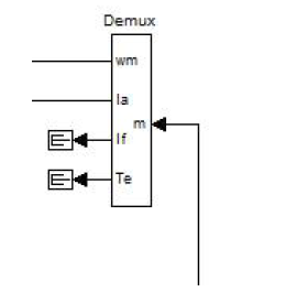
图10 为速度与电流反馈模块,由电枢端取得电枢电流与转子转速,输出信号为速度反馈信号wm 与电流反馈信号Ia。该模块的功能为获得电机转速反馈量与电枢电流反馈量以形成负反馈控制。
8、反馈电流滤波模块

9、示波器模块
仿真结果分析
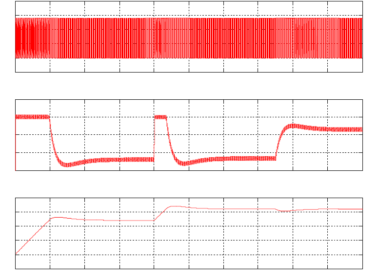
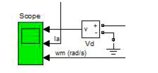
按照仿真模型原设定参数进行仿真,得到仿真结果如图13 所示。0~0.6s 为直流电机起动阶段,0.8s 时突然改变给定速度,1.5s 时突然改变负载转矩。由于电流的变化比较频繁,电流调节器LT 的输出电平高低变化频繁,GTO的开关频率很高,所以在当前的时间坐标轴来看,直流电机电枢电压Va 波形为带状,将时基放大之后,观察电枢电压波形,如图14,可以看出电枢电压为一脉宽调制波(PWM 波),当LT 检测到电流反馈值与给定值相差超过滞环带宽时改变GTO 的导通或关断状态,从而形成脉宽调制波。

1、起动阶段
起动阶段可以分为三个阶段。
(1)起动
最开始直流电机进行起动。起动时电机速度反馈ufn 为0,突加给定速度ug=120rad/s,速度调节器ST 输入Δun=ug,ST 饱和输出限幅值Idmax,速度作开环控制。电流给定值为Idmax,电流反馈值为0,两者之差超过了电流滞环调节器LT 的滞环宽度,LT 输出高电平,GTO 导通,电枢两端电压为280V,电枢电流达到最大值Idmax。由于电磁反应速度很快,所以在图上基本上看不到电枢电流由0 变为最大值的过程,电枢电流近似阶跃地到达了最大值。此时电机转子的转速还来不及变化仍然为0。
(2)加速
0~0.2s 期间为电机的加速阶段。在此阶段,电机由于转速反应比较慢,ufn<<ug,Δun=ug-ufn 仍然很大,速度调节器ST 仍作饱和限幅,电流调节器LT以Idmax 为电流给定值进行调节,电枢电流一直维持Idmax,电机转子在最大电流产生的最大转矩下以最大的加速度加速,速度一直增大至接近给定转速。速度作开环调节,实际上是电流单闭环系统。
(3)稳定
0.2~0.4s 期间电机双闭环系统调节至稳定。在此阶段,电机转子已经加速到接近额定转速,Δun=ug-ufn 很小,速度调节器ST 作PI 调节,输出电流给定值un下降,电流调节器输入Δui=un-ufi 变小,所以在LT 的调节下,电枢电流开始下降至稳定值,由于速度调节器的积分作用,速度有惯性,会出现速度超调的现象,之后在速度、电流双闭环系统的调节作用下,转速与电枢电流都趋于稳定值。
2、给定速度突变
在0.8s 时速度调节器ST 的给定速度信号ug 发生了突变,由原来的120rad/s阶跃变为160rad/s,在速度、电流双闭环系统的调节下,转速与电流发生变化,具体分为两个阶段进行分析。
(1)加速
此过程与直流电机起动时的加速阶段类似。此时由于ufn<<ug,速度调节器的输入信号Δun=ug-ufn 很大,速度调节器ST 饱和输出限幅值,电流调节器LT 的给定电流信号为Idmax,随后LT 进行调节,使得电枢电流一直维持Idmax,电机转子在Idmax 产生的最大转矩Tmax 下以最大的加速度加速,从速度的波形也可以看出此加速阶段波形上升的斜率与起动时加速阶段的斜率相同,速度一直增大至接近给定转速160rad/s。速度作开环调节,实际上是电流单闭环系统。
(2)稳定
此过程与直流电机起动时的稳定阶段类似。此时由于转速以接近给定转速,Δun=ug-ufn 很小,速度调节器ST 作PI 调节,输出电流给定值un 下降,电流调节器输入Δui=un-ufi 变小,所以在LT 的调节下,电枢电流开始下降至稳定值,由于速度调节器的积分作用,速度有惯性,会出现速度超调的现象,之后在速度、电流双闭环系统的调节作用下,转速与电枢电流都趋于稳定值。
3、负载转矩突变
在1.5s 时直流电机轴上的负载转矩TL 发生突变,由原来的5N·m 阶跃变为25N·m,此时负载转矩大于电磁转矩,电机减速,转速稍微有所下降,转速给定信号ug 不变,速度调节器ST 的输入信号Δun=ug-ufn 增大,但是增大的幅度比较小,所以ST 作PI 调节,其输出信号即电流调节器LT 的给定信号un 变大,LT的输入信号Δui=un-ufi 变大,LT 进行闭环调节,增大电枢电流从而增大电磁转矩,直至电流稍微有所超调,此时电磁转矩大于负载转矩,电机加速,速度恢复到给定值,ST 的输入信号减小,输出LT 的给定值变小,电流稍微下降,直到电磁转矩等于负载转矩,转矩平衡,电流维持新的稳定值,电磁转矩比原来大,所以电流比原来大。此过程为速度、电流双闭环调节。
大家可以自行对KPKI等参数对电机的影响进行分析。
最后
以上就是跳跃酒窝最近收集整理的关于直流电机双闭环调速系统MATLAB仿真的全部内容,更多相关直流电机双闭环调速系统MATLAB仿真内容请搜索靠谱客的其他文章。


发表评论 取消回复