STM32库函数:通用同步/异步收发器(USART)部分代码细究
一、UART 和 USART
1、UART:universal asynchronous receiver and transmitter通用异步收发器;
2、USART:universal synchronous asynchronous receiver and transmitter通用同步异步收发器。
一般而言,单片机中,名称为UART的接口一般只能用于异步串行通讯,而名称为USART的接口既可以用于同步串行通讯,也能用于异步串行通讯。
二、全双工 和 半双工 和 单工
一、单工
数据只在一个方向上传输,不能实现双方通信。如:电视、广播。
二、半双工
允许数据在两个方向上传输,但是同一时间数据只能在一个方向上传输,其实际上是切换的单工,如:对讲机。
三、全双工
允许数据在两个方向上同时传输,如 :手机通话。
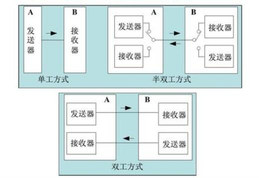
(图片来源于网络)
三、 ST USART 基础知识
1、STM32F103xC、 STM32F103xD和STM32F103xE增强型系列产品中,内置了3个通用同步/异步收发
器(USART1、 USART2和USART3),和2个通用异步收发器(UART4和UART5)。
2、这5个接口提供异步通信、支持IrDA SIR ENDEC传输编解码、多处理器通信模式、单线半双工通信模式和LIN主/从功能。
3、USART1接口通信速率可达4.5兆位/秒,其他接口的通信速率可达2.25兆位/秒。
4、USART1、 USART2和USART3接口具有硬件的CTS和RTS信号管理、兼容ISO7816的智能卡模式和类SPI通信模式,除了UART5之外所有其他接口都可以使用DMA操作。
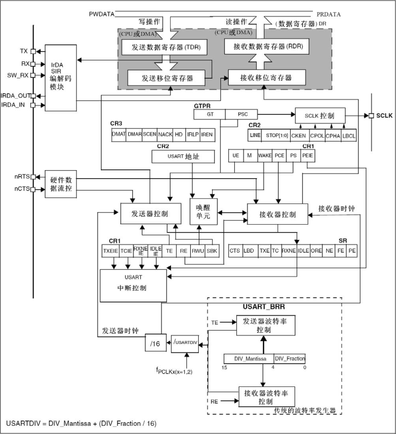
USART框图
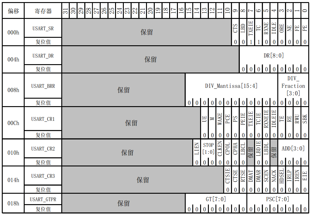
 USART 寄存器
四、 USART 库函数
USART的相关库函数较多,整体功能也比较复杂,本文不会全部讲解,只讲解普通功能常用的几个函数。
void USART_DeInit(USART_TypeDef* USARTx);
void USART_Init(USART_TypeDef* USARTx, USART_InitTypeDef* USART_InitStruct);
void USART_StructInit(USART_InitTypeDef* USART_InitStruct);
void USART_ClockInit(USART_TypeDef* USARTx, USART_ClockInitTypeDef* USART_ClockInitStruct);
void USART_ClockStructInit(USART_ClockInitTypeDef* USART_ClockInitStruct);
void USART_Cmd(USART_TypeDef* USARTx, FunctionalState NewState);
void USART_ITConfig(USART_TypeDef* USARTx, uint16_t USART_IT, FunctionalState NewState);
void USART_DMACmd(USART_TypeDef* USARTx, uint16_t USART_DMAReq, FunctionalState NewState);
void USART_SetAddress(USART_TypeDef* USARTx, uint8_t USART_Address);
void USART_WakeUpConfig(USART_TypeDef* USARTx, uint16_t USART_WakeUp);
void USART_ReceiverWakeUpCmd(USART_TypeDef* USARTx, FunctionalState NewState);
void USART_LINBreakDetectLengthConfig(USART_TypeDef* USARTx, uint16_t USART_LINBreakDetectLength);
void USART_LINCmd(USART_TypeDef* USARTx, FunctionalState NewState);
void USART_SendData(USART_TypeDef* USARTx, uint16_t Data);
uint16_t USART_ReceiveData(USART_TypeDef* USARTx);
void USART_SendBreak(USART_TypeDef* USARTx);
void USART_SetGuardTime(USART_TypeDef* USARTx, uint8_t USART_GuardTime);
void USART_SetPrescaler(USART_TypeDef* USARTx, uint8_t USART_Prescaler);
void USART_SmartCardCmd(USART_TypeDef* USARTx, FunctionalState NewState);
void USART_SmartCardNACKCmd(USART_TypeDef* USARTx, FunctionalState NewState);
void USART_HalfDuplexCmd(USART_TypeDef* USARTx, FunctionalState NewState);
void USART_OverSampling8Cmd(USART_TypeDef* USARTx, FunctionalState NewState);
void USART_OneBitMethodCmd(USART_TypeDef* USARTx, FunctionalState NewState);
void USART_IrDAConfig(USART_TypeDef* USARTx, uint16_t USART_IrDAMode);
void USART_IrDACmd(USART_TypeDef* USARTx, FunctionalState NewState);
FlagStatus USART_GetFlagStatus(USART_TypeDef* USARTx, uint16_t USART_FLAG);
void USART_ClearFlag(USART_TypeDef* USARTx, uint16_t USART_FLAG);
ITStatus USART_GetITStatus(USART_TypeDef* USARTx, uint16_t USART_IT);
void USART_ClearITPendingBit(USART_TypeDef* USARTx, uint16_t USART_IT);
USART寄存器列表及其复位值
寄存器结构体定义
typedef struct
{
  __IO uint16_t SR;
  uint16_t  RESERVED0;
  __IO uint16_t DR;
  uint16_t  RESERVED1;
  __IO uint16_t BRR;
  uint16_t  RESERVED2;
  __IO uint16_t CR1;
  uint16_t  RESERVED3;
  __IO uint16_t CR2;
  uint16_t  RESERVED4;
  __IO uint16_t CR3;
  uint16_t  RESERVED5;
  __IO uint16_t GTPR;
  uint16_t  RESERVED6;
} USART_TypeDef;
五、串口初始化函数
void USART_Init(USART_TypeDef* USARTx, USART_InitTypeDef* USART_InitStruct)
{
uint32_t tmpreg = 0x00, apbclock = 0x00;
uint32_t integerdivider = 0x00;
uint32_t fractionaldivider = 0x00;
uint32_t usartxbase = 0;
RCC_ClocksTypeDef RCC_ClocksStatus;
/* Check the parameters */
assert_param(IS_USART_ALL_PERIPH(USARTx));
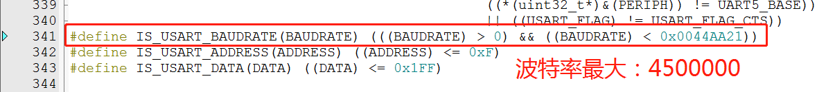
assert_param(IS_USART_BAUDRATE(USART_InitStruct->USART_BaudRate));
assert_param(IS_USART_WORD_LENGTH(USART_InitStruct->USART_WordLength));
assert_param(IS_USART_STOPBITS(USART_InitStruct->USART_StopBits));
assert_param(IS_USART_PARITY(USART_InitStruct->USART_Parity));
assert_param(IS_USART_MODE(USART_InitStruct->USART_Mode));
assert_param(IS_USART_HARDWARE_FLOW_CONTROL(USART_InitStruct->USART_HardwareFlowControl));
/* The hardware flow control is available only for USART1, USART2 and USART3 */
if (USART_InitStruct->USART_HardwareFlowControl != USART_HardwareFlowControl_None)
{
assert_param(IS_USART_123_PERIPH(USARTx));
}
usartxbase = (uint32_t)USARTx;
/*---------------------------- USART CR2 Configuration -----------------------*/
tmpreg = USARTx->CR2;
/* Clear STOP[13:12] bits */
tmpreg &= CR2_STOP_CLEAR_Mask;
/* Configure the USART Stop Bits, Clock, CPOL, CPHA and LastBit ------------*/
/* Set STOP[13:12] bits according to USART_StopBits value */
tmpreg |= (uint32_t)USART_InitStruct->USART_StopBits;
/* Write to USART CR2 */
USARTx->CR2 = (uint16_t)tmpreg;
/*---------------------------- USART CR1 Configuration -----------------------*/
tmpreg = USARTx->CR1;
/* Clear M, PCE, PS, TE and RE bits */
tmpreg &= CR1_CLEAR_Mask;
/* Configure the USART Word Length, Parity and mode ----------------------- */
/* Set the M bits according to USART_WordLength value */
/* Set PCE and PS bits according to USART_Parity value */
/* Set TE and RE bits according to USART_Mode value */
tmpreg |= (uint32_t)USART_InitStruct->USART_WordLength | USART_InitStruct->USART_Parity |
USART_InitStruct->USART_Mode;
/* Write to USART CR1 */
USARTx->CR1 = (uint16_t)tmpreg;
/*---------------------------- USART CR3 Configuration -----------------------*/
tmpreg = USARTx->CR3;
/* Clear CTSE and RTSE bits */
tmpreg &= CR3_CLEAR_Mask;
/* Configure the USART HFC -------------------------------------------------*/
/* Set CTSE and RTSE bits according to USART_HardwareFlowControl value */
tmpreg |= USART_InitStruct->USART_HardwareFlowControl;
/* Write to USART CR3 */
USARTx->CR3 = (uint16_t)tmpreg;
/*---------------------------- USART BRR Configuration -----------------------*/
/* Configure the USART Baud Rate -------------------------------------------*/
RCC_GetClocksFreq(&RCC_ClocksStatus);
if (usartxbase == USART1_BASE)
{
apbclock = RCC_ClocksStatus.PCLK2_Frequency;
}
else
{
apbclock = RCC_ClocksStatus.PCLK1_Frequency;
}
/* Determine the integer part */
if ((USARTx->CR1 & CR1_OVER8_Set) != 0)
{
/* Integer part computing in case Oversampling mode is 8 Samples */
integerdivider = ((25 * apbclock) / (2 * (USART_InitStruct->USART_BaudRate)));
}
else /* if ((USARTx->CR1 & CR1_OVER8_Set) == 0) */
{
/* Integer part computing in case Oversampling mode is 16 Samples */
integerdivider = ((25 * apbclock) / (4 * (USART_InitStruct->USART_BaudRate)));
}
tmpreg = (integerdivider / 100) << 4;
/* Determine the fractional part */
fractionaldivider = integerdivider - (100 * (tmpreg >> 4));
/* Implement the fractional part in the register */
if ((USARTx->CR1 & CR1_OVER8_Set) != 0)
{
tmpreg |= ((((fractionaldivider * 8) + 50) / 100)) & ((uint8_t)0x07);
}
else /* if ((USARTx->CR1 & CR1_OVER8_Set) == 0) */
{
tmpreg |= ((((fractionaldivider * 16) + 50) / 100)) & ((uint8_t)0x0F);
}
/* Write to USART BRR */
USARTx->BRR = (uint16_t)tmpreg;
}
/** @defgroup USART_Private_Defines
  * @{
  */

#define CR1_UE_Set                ((uint16_t)0x2000)  /*!< USART Enable Mask */
#define CR1_UE_Reset              ((uint16_t)0xDFFF)  /*!< USART Disable Mask */

#define CR1_WAKE_Mask             ((uint16_t)0xF7FF)  /*!< USART WakeUp Method Mask */

#define CR1_RWU_Set               ((uint16_t)0x0002)  /*!< USART mute mode Enable Mask */
#define CR1_RWU_Reset             ((uint16_t)0xFFFD)  /*!< USART mute mode Enable Mask */
#define CR1_SBK_Set               ((uint16_t)0x0001)  /*!< USART Break Character send Mask */
#define CR1_CLEAR_Mask            ((uint16_t)0xE9F3)  /*!< USART CR1 Mask */
#define CR2_Address_Mask          ((uint16_t)0xFFF0)  /*!< USART address Mask */

#define CR2_LINEN_Set              ((uint16_t)0x4000)  /*!< USART LIN Enable Mask */
#define CR2_LINEN_Reset            ((uint16_t)0xBFFF)  /*!< USART LIN Disable Mask */

#define CR2_LBDL_Mask             ((uint16_t)0xFFDF)  /*!< USART LIN Break detection Mask */
#define CR2_STOP_CLEAR_Mask       ((uint16_t)0xCFFF)  /*!< USART CR2 STOP Bits Mask */
#define CR2_CLOCK_CLEAR_Mask      ((uint16_t)0xF0FF)  /*!< USART CR2 Clock Mask */

#define CR3_SCEN_Set              ((uint16_t)0x0020)  /*!< USART SC Enable Mask */
#define CR3_SCEN_Reset            ((uint16_t)0xFFDF)  /*!< USART SC Disable Mask */

#define CR3_NACK_Set              ((uint16_t)0x0010)  /*!< USART SC NACK Enable Mask */
#define CR3_NACK_Reset            ((uint16_t)0xFFEF)  /*!< USART SC NACK Disable Mask */

#define CR3_HDSEL_Set             ((uint16_t)0x0008)  /*!< USART Half-Duplex Enable Mask */
#define CR3_HDSEL_Reset           ((uint16_t)0xFFF7)  /*!< USART Half-Duplex Disable Mask */

#define CR3_IRLP_Mask             ((uint16_t)0xFFFB)  /*!< USART IrDA LowPower mode Mask */
#define CR3_CLEAR_Mask            ((uint16_t)0xFCFF)  /*!< USART CR3 Mask */

#define CR3_IREN_Set              ((uint16_t)0x0002)  /*!< USART IrDA Enable Mask */
#define CR3_IREN_Reset            ((uint16_t)0xFFFD)  /*!< USART IrDA Disable Mask */
#define GTPR_LSB_Mask             ((uint16_t)0x00FF)  /*!< Guard Time Register LSB Mask */
#define GTPR_MSB_Mask             ((uint16_t)0xFF00)  /*!< Guard Time Register MSB Mask */
#define IT_Mask                   ((uint16_t)0x001F)  /*!< USART Interrupt Mask */

/* USART OverSampling-8 Mask */
#define CR1_OVER8_Set             ((u16)0x8000)  /* USART OVER8 mode Enable Mask */
#define CR1_OVER8_Reset           ((u16)0x7FFF)  /* USART OVER8 mode Disable Mask */

/* USART One Bit Sampling Mask */
#define CR3_ONEBITE_Set           ((u16)0x0800)  /* USART ONEBITE mode Enable Mask */
#define CR3_ONEBITE_Reset         ((u16)0xF7FF)  /* USART ONEBITE mode Disable Mask */
USART_InitTypeDef
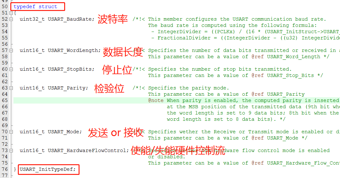
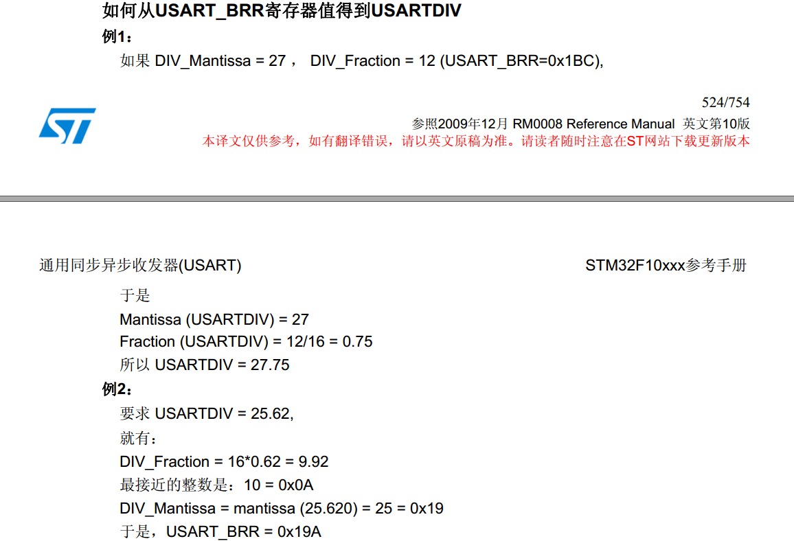
USART_BaudRate
接收器和发送器的波特率在USARTDIV的整数和小数寄存器中的值应设置成相同。
Tx / Rx 波特率 =fCK/(16*( USARTDIV ))
这里的fCK是给外设的时钟(PCLK1用于USART2、 3、 4、 5, PCLK2用于USART1)
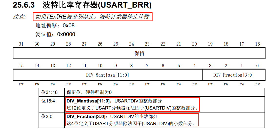
USARTDIV是一个无符号的定点数。这12位的值设置在USART_BRR寄存器。
注: 在写入USART_BRR之后,波特率计数器会被波特率寄存器的新值替换。因此,不要在通信进行中改变波特率寄存器的数值。
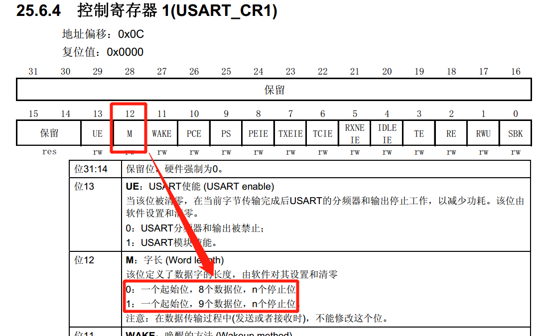
USART_WordLength
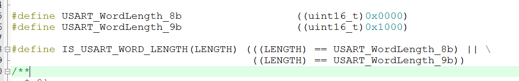 至于为何8位数长度据宏定义值为 0x0000, 9位数据长度宏定义值为0x1000,看下图:
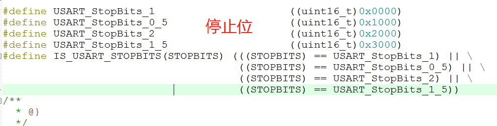
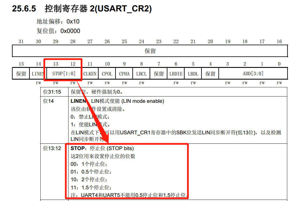
USART_StopBits
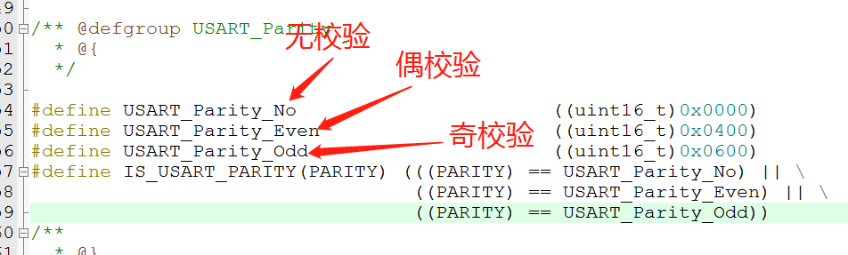
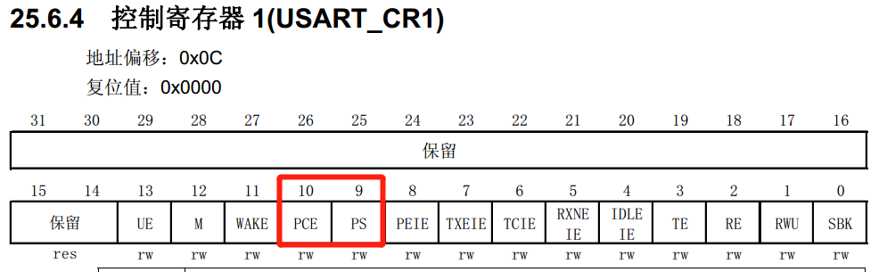
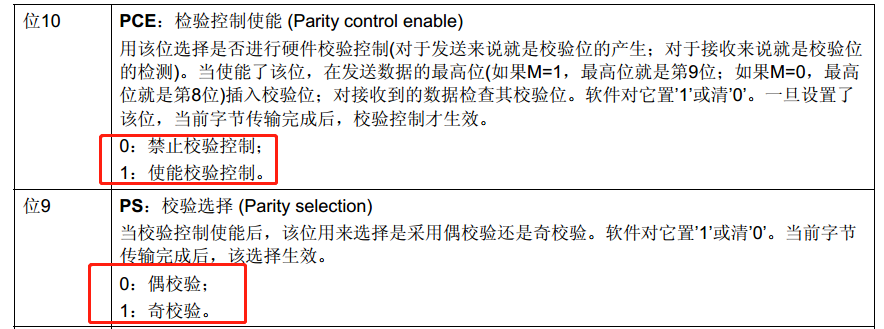
 USART_Parity
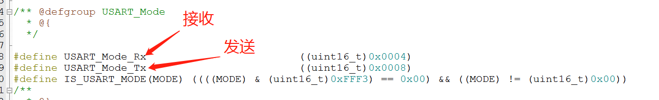
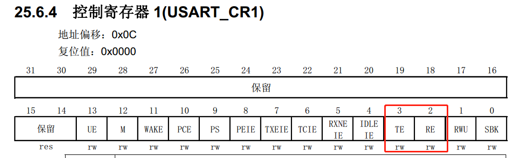
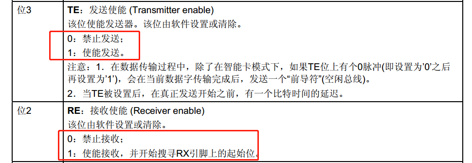
USART_Mode
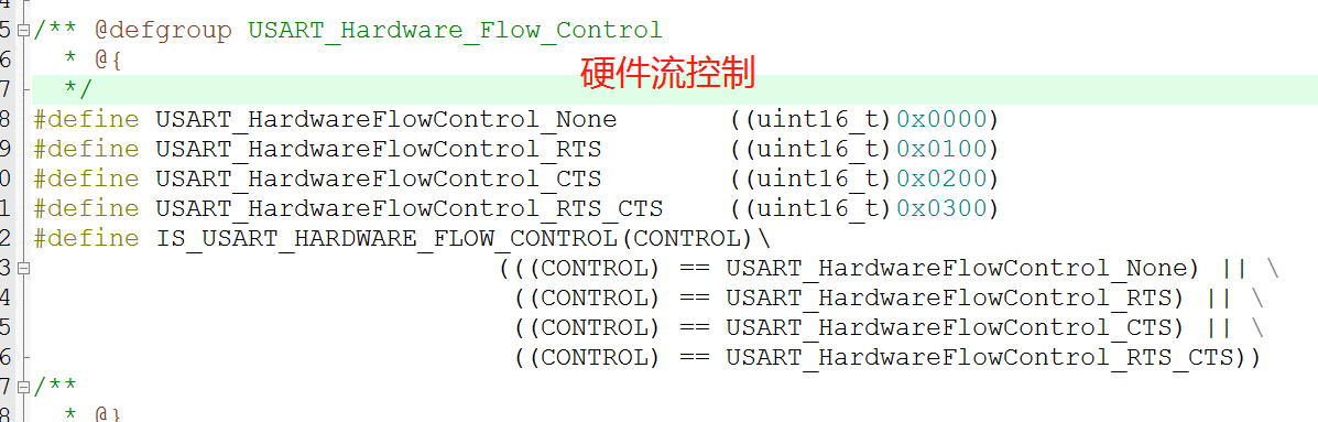
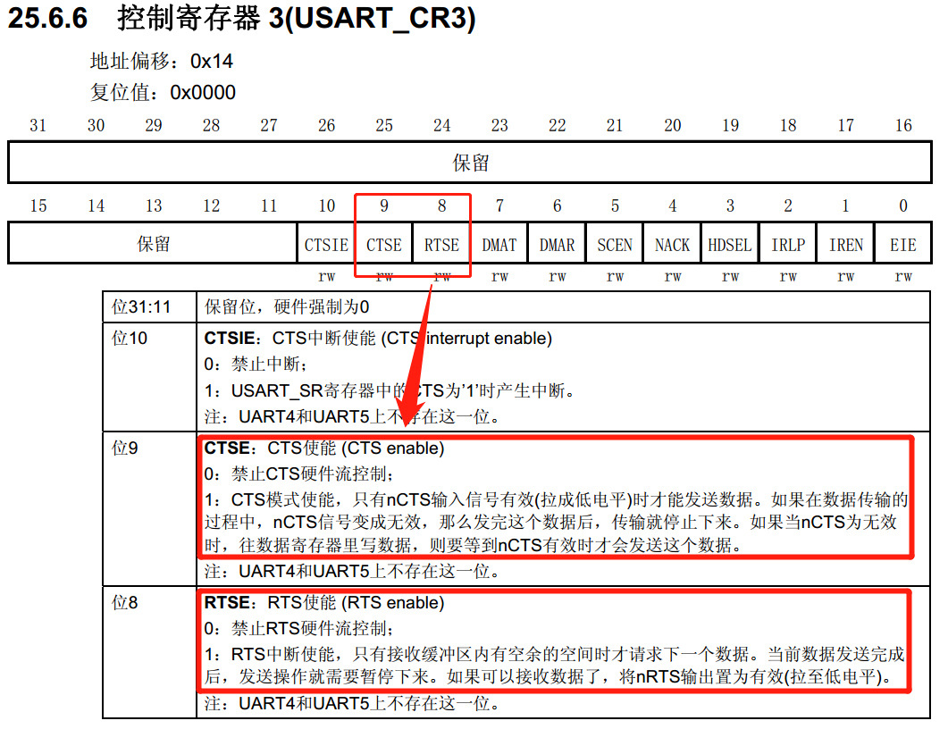
 USART_HardwareFlowControl
六、串口初始化代码示例
void uart_init(u32 bound){
  //GPIO端口设置
  GPIO_InitTypeDef GPIO_InitStructure;
	USART_InitTypeDef USART_InitStructure;
	NVIC_InitTypeDef NVIC_InitStructure;

	RCC_APB2PeriphClockCmd(RCC_APB2Periph_USART1|RCC_APB2Periph_GPIOA, ENABLE);	//使能USART1,GPIOA时钟

	//USART1_TX   GPIOA.9
  GPIO_InitStructure.GPIO_Pin = GPIO_Pin_9; //PA.9
  GPIO_InitStructure.GPIO_Speed = GPIO_Speed_50MHz;
  GPIO_InitStructure.GPIO_Mode = GPIO_Mode_AF_PP;	//复用推挽输出
  GPIO_Init(GPIOA, &GPIO_InitStructure);//初始化GPIOA.9

  //USART1_RX	  GPIOA.10初始化
  GPIO_InitStructure.GPIO_Pin = GPIO_Pin_10;//PA10
  GPIO_InitStructure.GPIO_Mode = GPIO_Mode_IN_FLOATING;//浮空输入
  GPIO_Init(GPIOA, &GPIO_InitStructure);//初始化GPIOA.10

  //Usart1 NVIC 配置
  NVIC_InitStructure.NVIC_IRQChannel = USART1_IRQn;
	NVIC_InitStructure.NVIC_IRQChannelPreemptionPriority=3 ;//抢占优先级3
	NVIC_InitStructure.NVIC_IRQChannelSubPriority = 3;		//子优先级3
	NVIC_InitStructure.NVIC_IRQChannelCmd = ENABLE;			//IRQ通道使能
	NVIC_Init(&NVIC_InitStructure);	//根据指定的参数初始化VIC寄存器

   //USART 初始化设置

	USART_InitStructure.USART_BaudRate = bound;//串口波特率
	USART_InitStructure.USART_WordLength = USART_WordLength_8b;//字长为8位数据格式
	USART_InitStructure.USART_StopBits = USART_StopBits_1;//一个停止位
	USART_InitStructure.USART_Parity = USART_Parity_No;//无奇偶校验位
	USART_InitStructure.USART_HardwareFlowControl = USART_HardwareFlowControl_None;//无硬件数据流控制
	USART_InitStructure.USART_Mode = USART_Mode_Rx | USART_Mode_Tx;	//收发模式

  USART_Init(USART1, &USART_InitStructure); //初始化串口1
  USART_ITConfig(USART1, USART_IT_RXNE, ENABLE);//开启串口接受中断
  USART_Cmd(USART1, ENABLE);                    //使能串口1

}
七、USART_Cmd 串口使能函数
void USART_Cmd(USART_TypeDef* USARTx, FunctionalState NewState)
{
/* Check the parameters */
assert_param(IS_USART_ALL_PERIPH(USARTx));
assert_param(IS_FUNCTIONAL_STATE(NewState));
if (NewState != DISABLE)
{
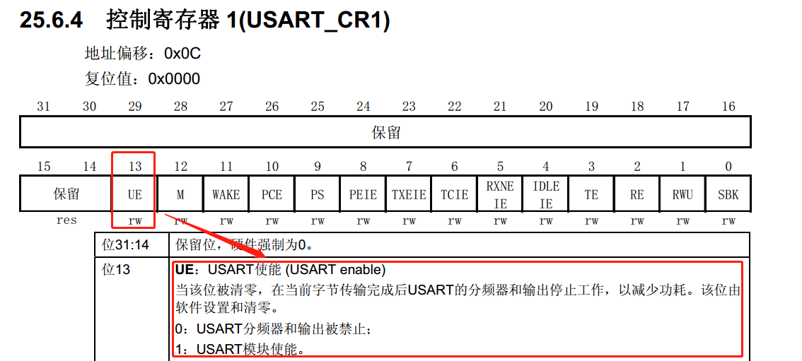
/* Enable the selected USART by setting the UE bit in the CR1 register */
USARTx->CR1 |= CR1_UE_Set; //按位或 置位该位数据时应保持其他位数据不发生变化
}
else
{
/* Disable the selected USART by clearing the UE bit in the CR1 register */
USARTx->CR1 &= CR1_UE_Reset; //按位与 复位该位数据时应保持其他位数据不发生变化
}
}
#define CR1_UE_Set                ((uint16_t)0x2000)  /*!< USART Enable Mask */
#define CR1_UE_Reset              ((uint16_t)0xDFFF)  /*!< USART Disable Mask */
八、USART_ITConfig 串口中断配置函数
void USART_ITConfig(USART_TypeDef* USARTx, uint16_t USART_IT, FunctionalState NewState)
{
  uint32_t usartreg = 0x00, itpos = 0x00, itmask = 0x00;
  uint32_t usartxbase = 0x00;
  /* Check the parameters */
  assert_param(IS_USART_ALL_PERIPH(USARTx));
  assert_param(IS_USART_CONFIG_IT(USART_IT));
  assert_param(IS_FUNCTIONAL_STATE(NewState));
  /* The CTS interrupt is not available for UART4 and UART5 */
  if (USART_IT == USART_IT_CTS)
  {
    assert_param(IS_USART_123_PERIPH(USARTx));
  }

  usartxbase = (uint32_t)USARTx;

  /* Get the USART register index */
  usartreg = (((uint8_t)USART_IT) >> 0x05);

  /* Get the interrupt position */
  itpos = USART_IT & IT_Mask;
  itmask = (((uint32_t)0x01) << itpos);

  if (usartreg == 0x01) /* The IT is in CR1 register */
  {
    usartxbase += 0x0C;
  }
  else if (usartreg == 0x02) /* The IT is in CR2 register */
  {
    usartxbase += 0x10;
  }
  else /* The IT is in CR3 register */
  {
    usartxbase += 0x14;
  }
  if (NewState != DISABLE)
  {
    *(__IO uint32_t*)usartxbase  |= itmask;
  }
  else
  {
    *(__IO uint32_t*)usartxbase &= ~itmask;
  }
}
#define IT_Mask ((uint16_t)0x001F) /*!< USART Interrupt Mask */
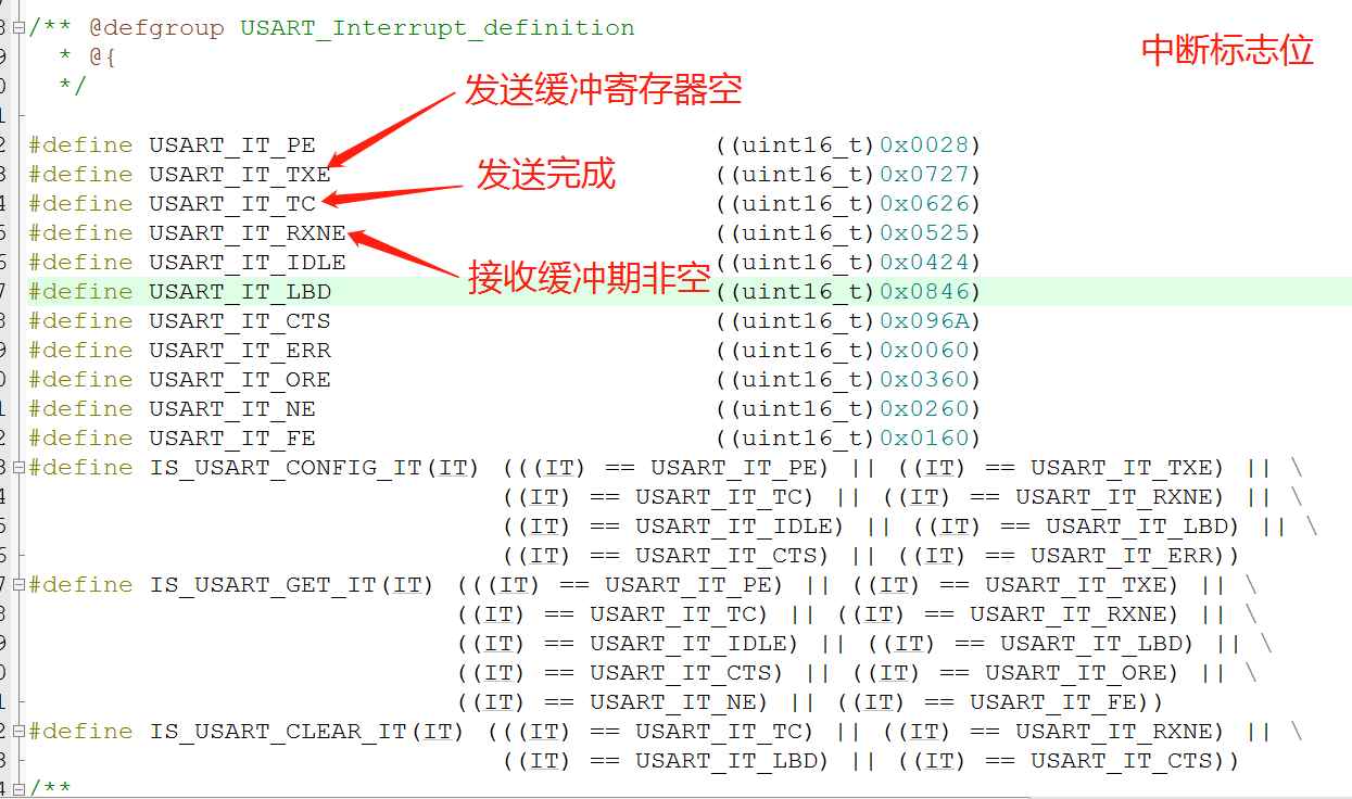
中断标志位定义
九、USART_GetITStatus 中断标志位获取
ITStatus USART_GetITStatus(USART_TypeDef* USARTx, uint16_t USART_IT)
{
  uint32_t bitpos = 0x00, itmask = 0x00, usartreg = 0x00;
  ITStatus bitstatus = RESET;
  /* Check the parameters */
  assert_param(IS_USART_ALL_PERIPH(USARTx));
  assert_param(IS_USART_GET_IT(USART_IT));
  /* The CTS interrupt is not available for UART4 and UART5 */
  if (USART_IT == USART_IT_CTS)
  {
    assert_param(IS_USART_123_PERIPH(USARTx));
  }

  /* Get the USART register index */
  usartreg = (((uint8_t)USART_IT) >> 0x05);
  /* Get the interrupt position */
  itmask = USART_IT & IT_Mask;
  itmask = (uint32_t)0x01 << itmask;

  if (usartreg == 0x01) /* The IT  is in CR1 register */
  {
    itmask &= USARTx->CR1;
  }
  else if (usartreg == 0x02) /* The IT  is in CR2 register */
  {
    itmask &= USARTx->CR2;
  }
  else /* The IT  is in CR3 register */
  {
    itmask &= USARTx->CR3;
  }

  bitpos = USART_IT >> 0x08;
  bitpos = (uint32_t)0x01 << bitpos;
  bitpos &= USARTx->SR;
  if ((itmask != (uint16_t)RESET)&&(bitpos != (uint16_t)RESET))
  {
    bitstatus = SET;
  }
  else
  {
    bitstatus = RESET;
  }

  return bitstatus;
}
十、USART_ClearITPendingBit 中断标志位清除
void USART_ClearITPendingBit(USART_TypeDef* USARTx, uint16_t USART_IT)
{
  uint16_t bitpos = 0x00, itmask = 0x00;
  /* Check the parameters */
  assert_param(IS_USART_ALL_PERIPH(USARTx));
  assert_param(IS_USART_CLEAR_IT(USART_IT));
  /* The CTS interrupt is not available for UART4 and UART5 */
  if (USART_IT == USART_IT_CTS)
  {
    assert_param(IS_USART_123_PERIPH(USARTx));
  }

  bitpos = USART_IT >> 0x08;
  itmask = ((uint16_t)0x01 << (uint16_t)bitpos);
  USARTx->SR = (uint16_t)~itmask;
}
十一、USART_GetFlagStatus 获取状态标志位
FlagStatus USART_GetFlagStatus(USART_TypeDef* USARTx, uint16_t USART_FLAG)
{
  FlagStatus bitstatus = RESET;
  /* Check the parameters */
  assert_param(IS_USART_ALL_PERIPH(USARTx));
  assert_param(IS_USART_FLAG(USART_FLAG));
  /* The CTS flag is not available for UART4 and UART5 */
  if (USART_FLAG == USART_FLAG_CTS)
  {
    assert_param(IS_USART_123_PERIPH(USARTx));
  }

  if ((USARTx->SR & USART_FLAG) != (uint16_t)RESET)
  {
    bitstatus = SET;
  }
  else
  {
    bitstatus = RESET;
  }
  return bitstatus;
}
十二、USART_ClearFlag 状态标志位清除
void USART_ClearFlag(USART_TypeDef* USARTx, uint16_t USART_FLAG)
{
  /* Check the parameters */
  assert_param(IS_USART_ALL_PERIPH(USARTx));
  assert_param(IS_USART_CLEAR_FLAG(USART_FLAG));
  /* The CTS flag is not available for UART4 and UART5 */
  if ((USART_FLAG & USART_FLAG_CTS) == USART_FLAG_CTS)
  {
    assert_param(IS_USART_123_PERIPH(USARTx));
  }

  USARTx->SR = (uint16_t)~USART_FLAG;
}
十三、串口发送函数
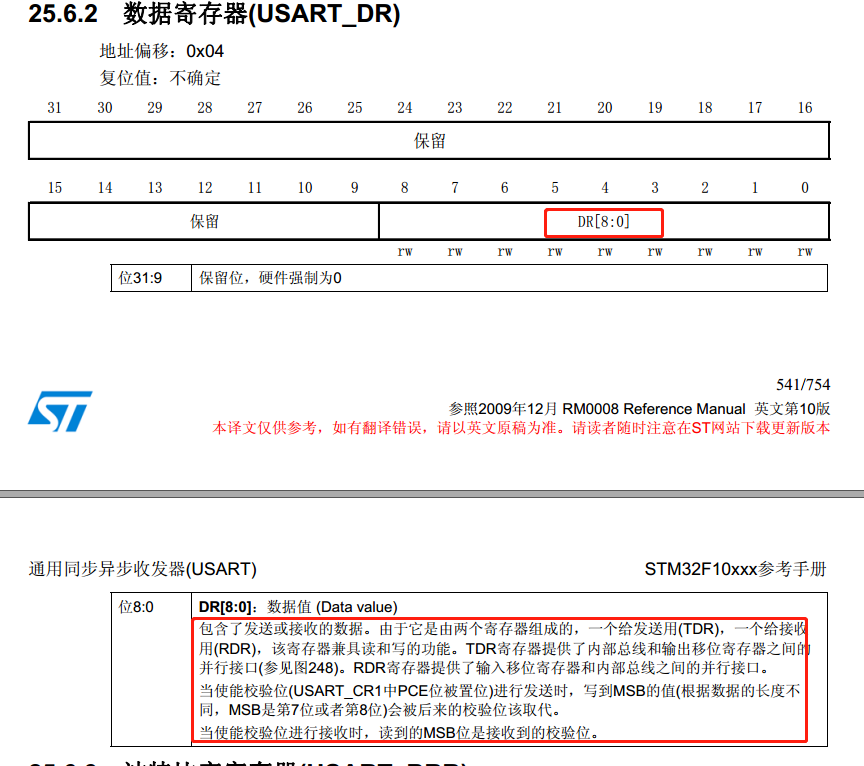
void USART_SendData(USART_TypeDef* USARTx, uint16_t Data)
{
  /* Check the parameters */
  assert_param(IS_USART_ALL_PERIPH(USARTx));
  assert_param(IS_USART_DATA(Data));

  /* Transmit Data */
  USARTx->DR = (Data & (uint16_t)0x01FF);

}
十四、串口接收函数
uint16_t USART_ReceiveData(USART_TypeDef* USARTx)
{
  /* Check the parameters */
  assert_param(IS_USART_ALL_PERIPH(USARTx));

  /* Receive Data */
  return (uint16_t)(USARTx->DR & (uint16_t)0x01FF);
}
十五、举例
//====================================================================
// Function Name : Getchar
// Description : 读串口接收寄存器函数
// Input : 串口号
// Output : None
// Return : 数据,返回0表示无效数据
//====================================================================
u8 Getchar(USART_TypeDef* USARTx)
{
if(USART_GetFlagStatus(USARTx,USART_FLAG_RBNE)) //接收缓冲区非空
{
return USART_ReceiveData(USARTx);
}
else
return 0;
}
//====================================================================
// Function Name : Putchar
// Description : 写串口发送寄存器函数
// Input : 串口号,数据
// Output : None
// Return : 数据,返回0表示无效数据
//====================================================================
void Putchar(USART_TypeDef* USARTx)
{
USART_SendData(USARTx, dat);
while(RESET == USART_SendData(USARTx, USART_FLAG_TC)); //等待发送完成
}
//====================================================================
// Function Name : 串口重定向
// Description : retarget the C library printf function to the USART
// Input :
// Output : None
// Return :
//====================================================================
int fputc(int ch, FILE *f)
{
USART_SendData(USART0, (uint8_t) ch);
while(RESET == USART_GetFlagStatus(USART0, USART_FLAG_TBE));
return ch;
}
//==============================================================================
// Function Name : PrintString
// Description : 串口输出字符串
// Input : 串口id, 需输出的字符指针
// Output : None
// Return : None
//==============================================================================
void PrintString(USART_TypeDef* USARTx, u8* chch)
{
while (*chch != '�')
Putchar(USARTx, *(chch++));
}
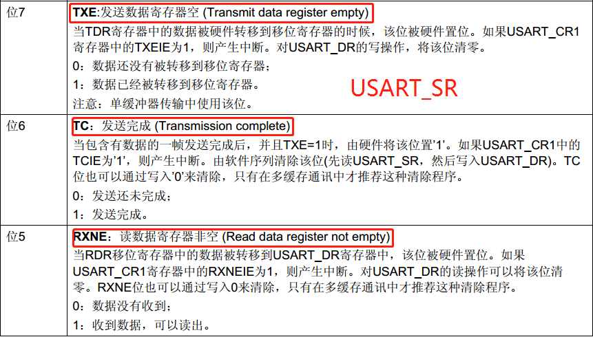
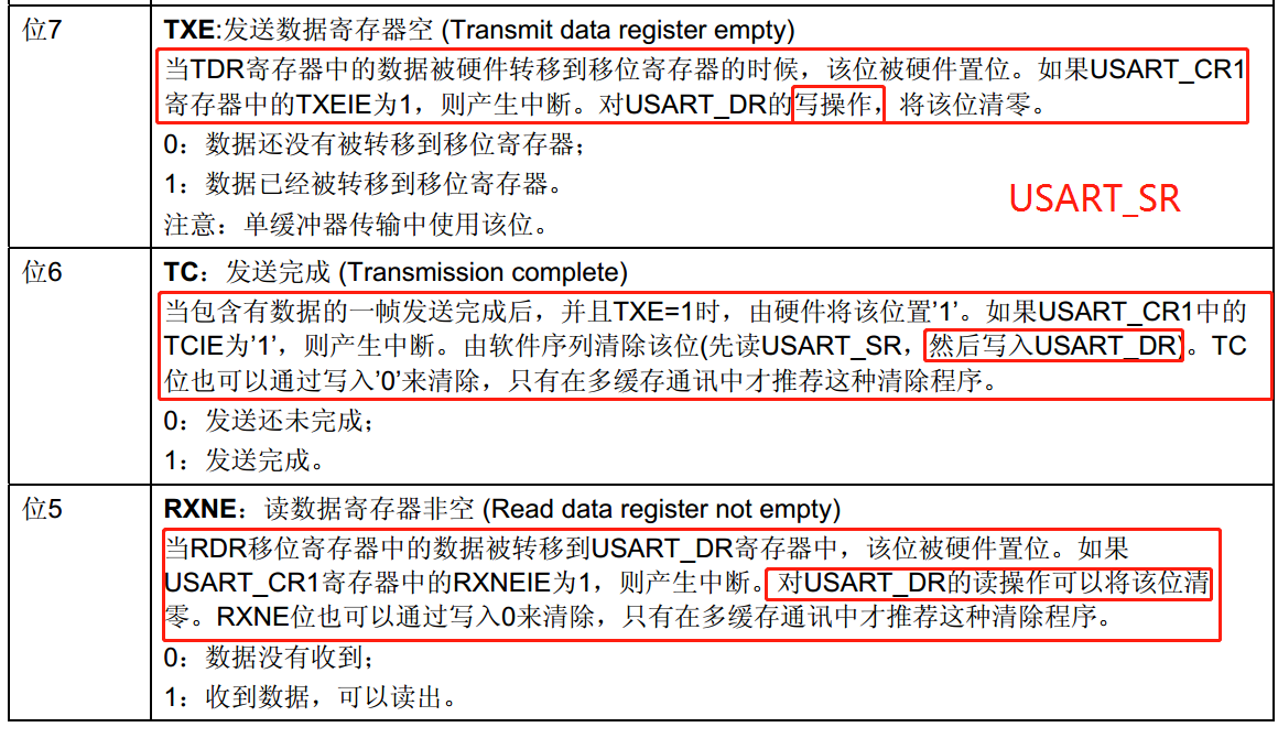
十六、串口中断标志位为何不需要用户手动清零
串口接收到数据,接收中断标志位为1,但是当你读USART_DR寄存器的时候,也就是读串口收到的数据时,硬件会自动的清除串口接收中断标志。所以,也可以不用开发者来清除。
我的理解:USART_DR的读写操作就是用户接收,发送数据的过程,用户接收,发送数据的过程其实就已经将中断标志位清0了。
最后
以上就是顺心航空最近收集整理的关于STM32库函数:通用同步/异步收发器(USART)部分代码细究的全部内容,更多相关STM32库函数内容请搜索靠谱客的其他文章。


发表评论 取消回复