实现这个主要是为了回顾对SVPWM原理的理解和推导过程以及s-function c语言的操作方法
SVPWM其实已经是业界常识了,TI,ST等企业已经帮大家敲好了代码,做好了demo板,写好了技术应用文档,想学的话去官网爬一爬,认真捣鼓一段时间就会了。
但是再熟的东西,一直不回顾也会忘记。一个例子就是我自己的游泳技能。我在一条小河边长大,高中之前每年夏天经常游泳,当然是狗刨,玩水很溜。从高中到工作,10年时间,我就没正经游过泳了。直到前年我去天坛游泳馆游泳,一跳下去,沉了,好不容易扑腾起来,还游不远,特别费力。后来花了持续半年,一共七八次的专门游泳训练才恢复游泳技能。基本蛙泳,自由泳才掌握了。
以此类推,自己的一些生存技能也是这样,要保持热度和敏感性。离开原有的项目,转战新项目快一年时间了,长时间没碰SVPWM了,容易生疏,闲来无事,在simulink里面重新写一写,保持感觉。
SVPWM算法在功率变换器上的使用十分基础和重要,例如PMSM的控制,三相PFC整流器,并网逆变器等需要ACDC,DCAC的地方。
SVPWM算法的过程大概是根据指令电压矢量在alpha和beta轴上的分量确定扇区,计算基本矢量的作用时间,根据扇区确定ABC三个桥臂的开关切换时间点,进而生成PWM。
在工作中其实我是最不喜欢做仿真的。因为有现成的硬件平台,硬件设计和软件设计都有成熟的产品对应,有什么想法,直接写代码去平台上做实验,反而更快,更直接,更立竿见影。但是呢,从原理上看,现实的世界里的东西,只要我们对他的模型洞察的足够深刻全面,把他搬到虚拟的世界里面去,它是可以基本和现实世界的系统是一致的。并且仿真的世界可简单可繁琐、有时候为了学习基本理论,研究前沿的不好实际实现或者不成熟的东西,用仿真也是挺好的。比如我现在要保持对SVPWM不遗忘,我想到的一个好的办法就是用C语言在simuink里面重新一笔一划的写一遍就行了。有人会说你回去看看以前的代码不就行了吗,这话没错。但是这样看,我上面说了我忘记了自己曾经会的游泳,那么我再看游泳教学视频,多看几遍,我就能恢复以前的水平吗?我觉得还是会打折扣。事实也是这样的,我本来觉得我花两个小时就能写好、调试好,但是从今天早上开始到现在下午七点,我才搞完,才开始写这篇文档。因为中间确实出现了几个小细节,花了我好些时间去寻找原因。
下面先放些图片说明过程,仿真模型和s-function的C语言程序,我会上传到我的资源里面,大家自己可以下载,不要C币,要点人民币,是为了筛选掉懒人,同时也给自己一点积继续做下去的动力。供有兴趣的人参考,仅仅用于学习哦,不能用于做产品哦,因为不能保证不因为这些程序而导致产品出问题。我这个仿真仅仅是为了练习对基本原理的敏感度而已。里面有很多考虑不周全的地方。
在CSDN首页搜索 :SVPWM_SfunctionCcsdn.rar,就可以看到我上传的资源,包含了下图的仿真模型,以及实现SPWM的.c和.h文件

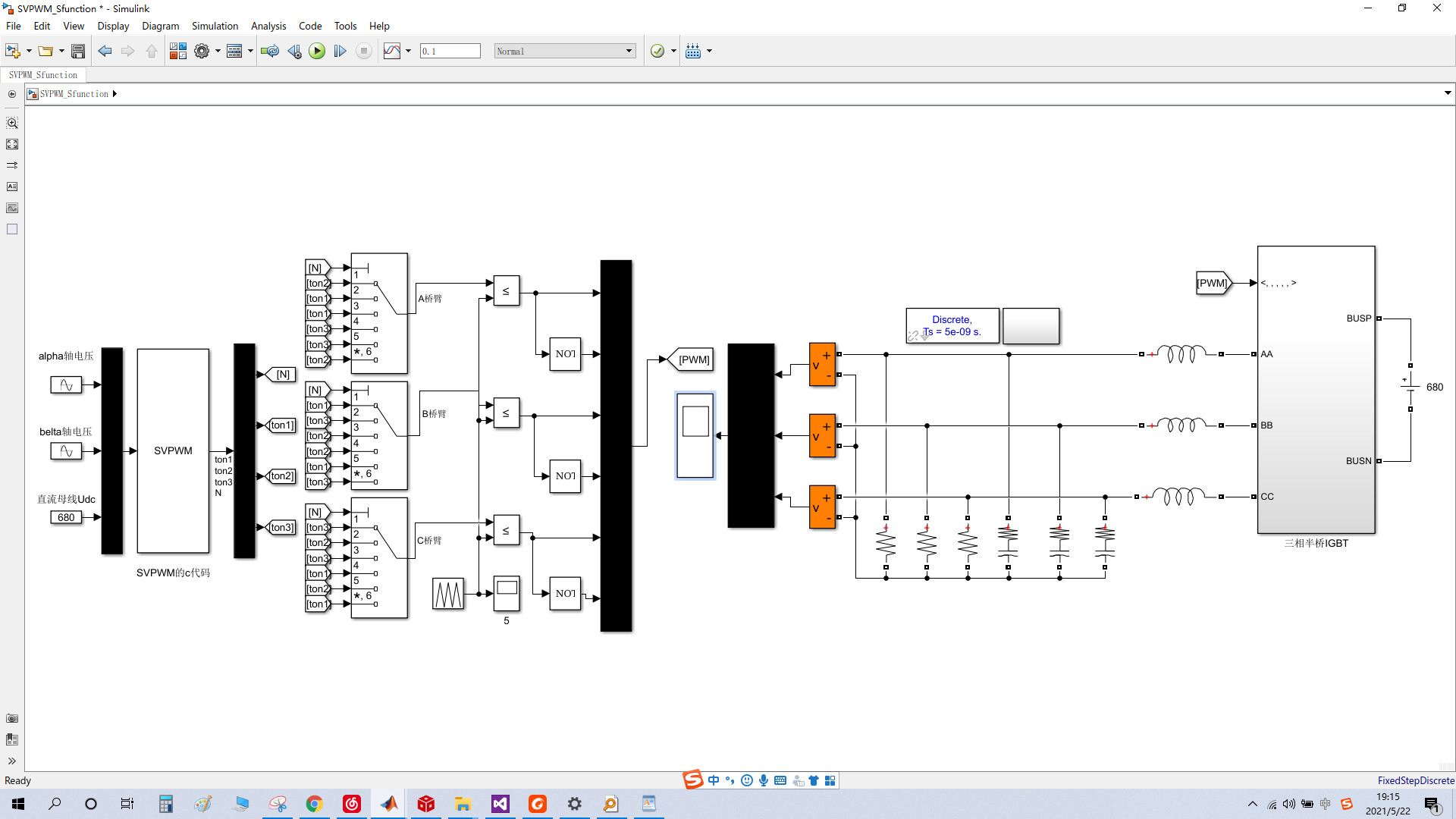
图1 基于S-function的SVPWM的c语言实现仿真原理图
输入信号是直流母线电压和指令电压信号在两相静止坐标系上的分量,这两个分量是相位互差90度的正弦量,以50hz为例。通过SVPWM算法的计算,输出三个桥臂开关切换的时间点和对应的扇区值,最后通过扇区基本矢量选择和基本时间因子分配到各个桥臂上去。

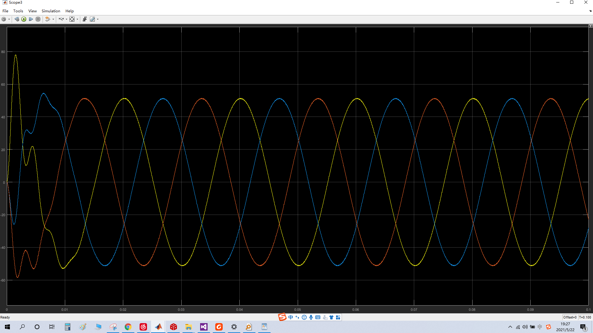
图2 ABC三个桥臂输出电压经过LC滤波器后的波形
在CSDN首页搜索 :SVPWM_SfunctionCcsdn.rar,就可以看到我上传的资源,包含了下图的仿真模型,以及实现SPWM的.c和.h文件
要是嫌下载麻烦,或者懒得出那几块钱的人民币,那么下面贴出程序,程序是在s-function中写的c代码,哈哈。用心看下面的程序,学习matlab的使用方法,一定可以复现上图的内容。在此强调仅用于学习啊,不具备工程意义。
/*
* sfuntmpl_basic.c: Basic 'C' template for a level 2 S-function.
*
* Copyright 1990-2013 The MathWorks, Inc.
*/
/*
* You must specify the S_FUNCTION_NAME as the name of your S-function
* (i.e. replace sfuntmpl_basic with the name of your S-function).
*输入变量有四个u[0]u[1]u[2]u[3],分别是指令电压在alpha和belta轴上的分量,母线电压,PWM三角载波
*输出变量有六个y[0]y[1]y[2]y[3],分别ABC三个桥臂0,1状态的切换时间点
*
*
*/
#define S_FUNCTION_NAME SVPWM
#define S_FUNCTION_LEVEL 2
#define HALF_SQRT3 0.86602540378443864676372317075294
#define SQRT3 1.7320508075688772935274463415059
#define Tpwm 0.0000625
typedef int int16;
typedef long int32;
typedef long long int64;
typedef unsigned int Uint16;
typedef unsigned long Uint32;
typedef unsigned long long Uint64;
typedef float float32;
typedef long double float64;
/*
* Need to include simstruc.h for the definition of the SimStruct and
* its associated macro definitions.
*/
#include "simstruc.h"
#include "math.h"
#include "SVPWM.h"
sSVPWM Svm;
/* Error handling
* --------------
*
* You should use the following technique to report errors encountered within
* an S-function:
*
* ssSetErrorStatus(S,"Error encountered due to ...");
* return;
*
* Note that the 2nd argument to ssSetErrorStatus must be persistent memory.
* It cannot be a local variable. For example the following will cause
* unpredictable errors:
*
* mdlOutputs()
* {
* char msg[256]; {ILLEGAL: to fix use "static char msg[256];"}
* sprintf(msg,"Error due to %s", string);
* ssSetErrorStatus(S,msg);
* return;
* }
*
*/
/*====================*
* S-function methods *
*====================*/
/* Function: mdlInitializeSizes ===============================================
* Abstract:
* The sizes information is used by Simulink to determine the S-function
* block's characteristics (number of inputs, outputs, states, etc.).
*/
static void mdlInitializeSizes(SimStruct *S)
{
ssSetNumSFcnParams(S, 0); /* Number of expected parameters */
if (ssGetNumSFcnParams(S) != ssGetSFcnParamsCount(S)) {
/* Return if number of expected != number of actual parameters */
return;
}
ssSetNumContStates(S, 0);
ssSetNumDiscStates(S, 0);
if (!ssSetNumInputPorts(S, 1)) return;
ssSetInputPortWidth(S, 0, 3);
ssSetInputPortRequiredContiguous(S, 0, true); /*direct input signal access*/
/*
* Set direct feedthrough flag (1=yes, 0=no).
* A port has direct feedthrough if the input is used in either
* the mdlOutputs or mdlGetTimeOfNextVarHit functions.
*/
ssSetInputPortDirectFeedThrough(S, 0, 1);
if (!ssSetNumOutputPorts(S, 1)) return;
ssSetOutputPortWidth(S, 0, 4);
ssSetNumSampleTimes(S, 1);
ssSetNumRWork(S, 0);
ssSetNumIWork(S, 0);
ssSetNumPWork(S, 0);
ssSetNumModes(S, 0);
ssSetNumNonsampledZCs(S, 0);
/* Specify the sim state compliance to be same as a built-in block */
ssSetSimStateCompliance(S, USE_DEFAULT_SIM_STATE);
ssSetOptions(S, 0);
}
/* Function: mdlInitializeSampleTimes =========================================
* Abstract:
* This function is used to specify the sample time(s) for your
* S-function. You must register the same number of sample times as
* specified in ssSetNumSampleTimes.
*/
static void mdlInitializeSampleTimes(SimStruct *S)
{
ssSetSampleTime(S, 0,0.0000625 ); //0.0000625 16K
ssSetOffsetTime(S, 0, 0.0);
}
#define MDL_INITIALIZE_CONDITIONS /* Change to #undef to remove function */
#if defined(MDL_INITIALIZE_CONDITIONS)
/* Function: mdlInitializeConditions ========================================
* Abstract:
* In this function, you should initialize the continuous and discrete
* states for your S-function block. The initial states are placed
* in the state vector, ssGetContStates(S) or ssGetRealDiscStates(S).
* You can also perform any other initialization activities that your
* S-function may require. Note, this routine will be called at the
* start of simulation and if it is present in an enabled subsystem
* configured to reset states, it will be call when the enabled subsystem
* restarts execution to reset the states.
*/
static void mdlInitializeConditions(SimStruct *S)
{
//Svm.kT=
}
#endif /* MDL_INITIALIZE_CONDITIONS */
#define MDL_START /* Change to #undef to remove function */
#if defined(MDL_START)
/* Function: mdlStart =======================================================
* Abstract:
* This function is called once at start of model execution. If you
* have states that should be initialized once, this is the place
* to do it.
*/
static void mdlStart(SimStruct *S)
{
}
#endif /* MDL_START */
/* Function: mdlOutputs =======================================================
* Abstract:
* In this function, you compute the outputs of your S-function
* block.
*/
static void mdlOutputs(SimStruct *S, int_T tid)
{
const real_T *u = (const real_T*) ssGetInputPortSignal(S,0);
real_T *y = ssGetOutputPortSignal(S,0);
//计算出来的指令电压矢量在alpha、belta轴上的分量是SVPWM模块的输入,信号采集进来后放在 Svm.alpha和Svm.belta中
Svm.alpha=u[0];
Svm.belta=u[1];
Svm.kT=SQRT3*Tpwm/u[2];
//扇区确定
//首先有三个变量装扇区计算的中间变量:Svm.U1; Svm.U2; Svm.U3;
Svm.U1=Svm.belta;
Svm.U2= HALF_SQRT3*Svm.alpha - 0.5*Svm.belta;
Svm.U3=-HALF_SQRT3*Svm.alpha - 0.5*Svm.belta;
//开始计算扇区对应的N值
Svm.N = 0;//首先给个初值
//完成N值得确定,N值与扇区的对应关系是 N 3 1 5 4 6 2
// 扇区 一 二 三 四 五 六
if(Svm.U1 > 0) Svm.N = Svm.N + 1;
if(Svm.U2 > 0) Svm.N = Svm.N + 2;
if(Svm.U3 > 0) Svm.N = Svm.N + 4;
//
//y[7]=Svm.U1;
//y[8]=Svm.U2;
// y[9]=Svm.U3;
//计算合成指令电压矢量的基本矢量的时间,不管指令电压在哪个扇区,也不管这个指令矢量在某个扇区的具体的那个位置,基本矢量的时间只需从三个表达式中选择,三个表达式用XYZ表示,选择的依据就是上面的N和sector的对应关系
//Svm.X = fabs(Svm.kT*Svm.belta);
//Svm.Y = fabs(Svm.kT*( HALF_SQRT3*Svm.alpha + 0.5*Svm.belta));
//Svm.Z = fabs(Svm.kT*(- HALF_SQRT3*Svm.alpha + 0.5*Svm.belta));
Svm.X = Svm.kT*Svm.belta;
Svm.Y = Svm.kT*( HALF_SQRT3*Svm.alpha + 0.5*Svm.belta);
Svm.Z = Svm.kT*(- HALF_SQRT3*Svm.alpha + 0.5*Svm.belta);
//y[7]=Svm.X;
//y[8]=Svm.Y;
//y[9]=Svm.Z;
switch (Svm.N)
{
case 1:Svm.T1 = Svm.Z;Svm.T2 = Svm.Y;break;//第二扇区
case 2:Svm.T1 = Svm.Y;Svm.T2 = -Svm.X;break;//第六扇区
case 3:Svm.T1 = -Svm.Z;Svm.T2 = Svm.X;break;//第一扇区
case 4:Svm.T1 = -Svm.X;Svm.T2 = Svm.Z;break;//第四扇区
case 5:Svm.T1 = Svm.X;Svm.T2 = -Svm.Y;break;//第三扇区
case 6:Svm.T1 = -Svm.Y;Svm.T2 = -Svm.Z;break;//第五扇区
default:break;
}
//作用时间抗饱和处理
if((Svm.T1 + Svm.T2) > Tpwm)
{
Svm.kAntisatur = Tpwm/(Svm.T1 + Svm.T2);
Svm.T1 = Svm.T1 * Svm.kAntisatur;
Svm.T2 = Svm.T2 * Svm.kAntisatur;
}
//作用时间计算,Svm.T1; Svm.T2;存放的是某个扇区的基本矢量作用时间
//根据袁雷表2-2确定三个比较桥臂的PWM切换时间点,从周期时间等于0开始
//三个切换时间点在任何一个扇区都是一样的表达式,但是对应的基本矢量不一样
Svm.ton1 = (Tpwm - Svm.T1 - Svm.T2)/4;//(Ts - var->T1 - var->T2)=T0+T7,均匀分配,(Ts - var->T1 - var->T2)/4=T0/2=T7/2
Svm.ton2 = Svm.ton1 + Svm.T1/2;
Svm.ton3 = Svm.ton2 + Svm.T2/2;
y[0]=Svm.N;
y[1]=Svm.ton1;
y[2]=Svm.ton2;
y[3]=Svm.ton3;
}
#define MDL_UPDATE /* Change to #undef to remove function */
#if defined(MDL_UPDATE)
/* Function: mdlUpdate ======================================================
* Abstract:
* This function is called once for every major integration time step.
* Discrete states are typically updated here, but this function is useful
* for performing any tasks that should only take place once per
* integration step.
*/
static void mdlUpdate(SimStruct *S, int_T tid)
{
}
#endif /* MDL_UPDATE */
#define MDL_DERIVATIVES /* Change to #undef to remove function */
#if defined(MDL_DERIVATIVES)
/* Function: mdlDerivatives =================================================
* Abstract:
* In this function, you compute the S-function block's derivatives.
* The derivatives are placed in the derivative vector, ssGetdX(S).
*/
static void mdlDerivatives(SimStruct *S)
{
}
#endif /* MDL_DERIVATIVES */
/* Function: mdlTerminate =====================================================
* Abstract:
* In this function, you should perform any actions that are necessary
* at the termination of a simulation. For example, if memory was
* allocated in mdlStart, this is the place to free it.
*/
static void mdlTerminate(SimStruct *S)
{
}
/*=============================*
* Required S-function trailer *
*=============================*/
#ifdef MATLAB_MEX_FILE /* Is this file being compiled as a MEX-file? */
#include "simulink.c" /* MEX-file interface mechanism */
#else
#include "cg_sfun.h" /* Code generation registration function */
#endif
1、三个标量,只要相加时刻等于0,就可以把他们放在复平面的三个互差120度的轴上。
对于理想的三相电网电压,各标量的瞬时值时刻随时间变化,他们在各自的轴上正负伸缩,带 着箭头,伸缩幅度是电压的赋值314V。即每个标量是一个矢量,矢量角度分别为0和180 度,120和-60度,240和30度。将这三个矢量相加,会得到一个新的矢量,他的赋值固定为 (3/2)*314,方向逆时针旋转。

对于三相半桥,其中点ABC对N点电压,为UAN,UBN,UCN,与三相电压电压类比,他们对应于三相电压UVW. 三相电网电压随时间是个正弦,而桥臂中点电压是一套离散的值,以UAN为例,其可能是:-Ubus*(2/3)、-Ubus*(1/3)、Ubus*(1/3)、Ubus*(2/3)、0五个值,其他两相也是如此。
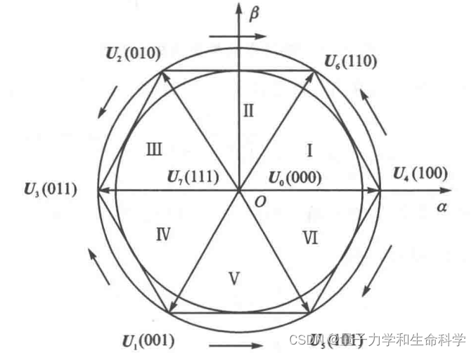
所以如果把UAN,UBN,UCN依次放在三相空间坐标系上,加上开关组合的约束,可以合成7个基本的矢量,例如100,即某个时间段,桥臂A上管开,桥臂BC下管开,从而导致VAN,VBN,VCN的电压分别如下图所示,将他们分解到虚轴和实轴上,然后在合成一个矢量,即下下图的矢量U4。这种开关组合形成的矢量,最大作用时间是Ts


最后
以上就是多情香水最近收集整理的关于SVPWM在S-function中用C语言实现在CSDN首页搜索 :SVPWM_SfunctionCcsdn.rar,就可以看到我上传的资源,包含了下图的仿真模型,以及实现SPWM的.c和.h文件的全部内容,更多相关SVPWM在S-function中用C语言实现在CSDN首页搜索内容请搜索靠谱客的其他文章。


发表评论 取消回复