该文章为汇总文章Verilog学习代码总结的状态机——交通灯部分。
该状态机为mealy型时序电路。
采用三段式设计方式。
题目
设计一个交通灯控制器。一个十字交叉路口,东西方向为主干道(HighWay),南北方向为副干道(CountryWay) 。副干道车辆很少,因此在交叉路口处有车辆探测器(Sensor) ,可以判断副干道是否有车。如果没有车,则主干道始终绿灯(Green) ;如果副干道有车,则在主干道通行40秒后,主干道红灯(Red),而副干道绿灯,通行时间为20秒。这时无论副干道有无车,副干道都要红灯,而主干道绿灯。从绿灯到红灯的转换中间有4秒黄灯(Yellow) 。
要求:
1.画出有限状态机,标明状态转换条件;
2.写出程序代码,标注说明和解释;
3.写出验证程序,对设计进行全面的验证。
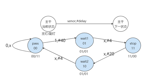
状态转换图
源代码
该程序源代码分为2子模块(计数器模块+交通灯模块)+顶模块
计数器模块
module counter(out,clk,enable,rst);
output[6:0]  out;
input clk, rst,enable;
reg[6:0] out;

always @ (posedge rst or posedge clk) begin
  if (rst) begin
    out <= 8'b0;
    end else if (enable) begin
    out <= (out + 1)%69;
  end
end

endmodule
交通灯模块
module light(highWay,countryWay,counter_enable,clk,rst,senor,count);
input clk,rst,senor;
input [6:0] count;
output counter_enable;
output [1:0] highWay,countryWay;
reg counter_enable;
reg [1:0] highWay,countryWay;
//标志计数状态
wire [6:0] count;

//主干状态,副干状态与之对应
reg [1:0] cur_state,next_state;
//灯输出结果常量
parameter GREEN = 2'b00,
          YELLOW = 2'b01,
          RED = 2'b11;
//状态常量
parameter PASS = 2'b00,
          WAIT1 = 2'b01,
          WAIT2 = 2'b10,
          STOP = 2'b11;

//根据下一状态或重置改变现在状态
always @(posedge rst or posedge clk) begin
  if(rst) begin
    cur_state <= PASS;
    next_state <= PASS;
    counter_enable <= 0;
  end else begin
    cur_state <= next_state;
  end
end

//不同状态不同输出
always @(cur_state) begin
  case (cur_state)
    PASS:begin
      highWay = GREEN;
      countryWay = RED;
    end
    WAIT1:begin
      highWay = YELLOW;
      countryWay = YELLOW;
    end
    WAIT2:begin
      highWay = YELLOW;
      countryWay = YELLOW;
    end
    STOP:begin
      highWay = RED;
      countryWay = GREEN;
    end
    default: begin
      highWay = GREEN;
      countryWay = RED;
    end
  endcase
end

//根据输入改变下一预设状态
always @(senor or count) begin
  next_state = PASS;
  case (cur_state)
    PASS:begin
      if (senor) begin
        if (count==40) begin
          next_state = WAIT1;
        end
        counter_enable = 1;
      end else begin
        counter_enable = 0;
      end
    end
    WAIT1:begin
      next_state = (count==44)?STOP:WAIT1;
    end
    WAIT2:begin
      next_state = (count==68)?PASS:WAIT2;
    end
    STOP:begin
      next_state = (count==64)?WAIT2:STOP;
    end
  endcase
end

endmodule
顶层模块
module top(highWay,countryWay,clk,rst,senor);
input clk,rst,senor;
output [1:0] highWay,countryWay;
wire counter_enable;
wire [6:0] count;

light i1(.highWay(highWay),.countryWay(countryWay),
  .counter_enable(counter_enable),
  .clk(clk),.rst(rst),
  .senor(senor),.count(count));

counter c1(.out(count),.clk(clk),
  .enable(counter_enable),.rst(rst));

endmodule
注意:当前代码中,默认了主干副干状态相互对应,red(主)-green(副),yellow(主)-yellow(副),green(主)-red(副)。
但实际上不是这样。
很多交通灯设计时,只有在red->green时需要穿插一个黄灯,正如题干最后一句。所以我这样的设计实际上是不符合题干要求的。
如果你想做一个更符合实际的,那么你需要再增加两个变量:cur_state2 和next_state2来保存副干状态。同时将状态机中的WAIT1状态删去,使得PASS直接指向STOP。
测试代码
`timescale 1ns/1ns
module tb_light;
reg clk,rst,senor;
wire [1:0] highWay,countryWay;
parameter INTERVAL = 10;

//初始化各值
initial begin
    clk = 1'b0;
    rst = 1'b0;
    senor = 1'b0;
end

//设定时钟周期
initial
  forever #(INTERVAL/2) clk = ~clk;

//重置模块
initial begin
  #INTERVAL rst = 1;
  #INTERVAL rst = 0;
end

initial begin
  //测试副干有车情况
  #(5*INTERVAL) senor = 1'b1;
  //测试副干无车情况
  #(60*INTERVAL) senor = 1'b0;
  #(100*INTERVAL) $finish;
end

//实例化模块
top t1(highWay,countryWay,clk,rst,senor);

endmodule
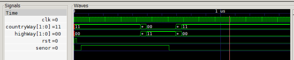
注意:交通灯模块中是用senor来判断是否在计时状态的。如果测试代码中,使senor=0时是在主干PASS的状态(senor=0意味着副干车没了,在主干PASS的状态下,副干原本的车突然没了?路口调头怕是来不及吧……所以本身算是一个伪命题——当然这排除了设备出故障情况),注意到交通灯模块并没有对计数器模块进行清零,所以下一次使senor=1时,主干通行时间可能会小于40S。
模拟仿真
最后
以上就是潇洒方盒最近收集整理的关于交通灯状态机verilog的全部内容,更多相关交通灯状态机verilog内容请搜索靠谱客的其他文章。


发表评论 取消回复