1 PMSM直接转矩控制原理
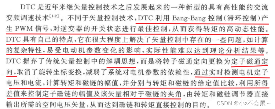
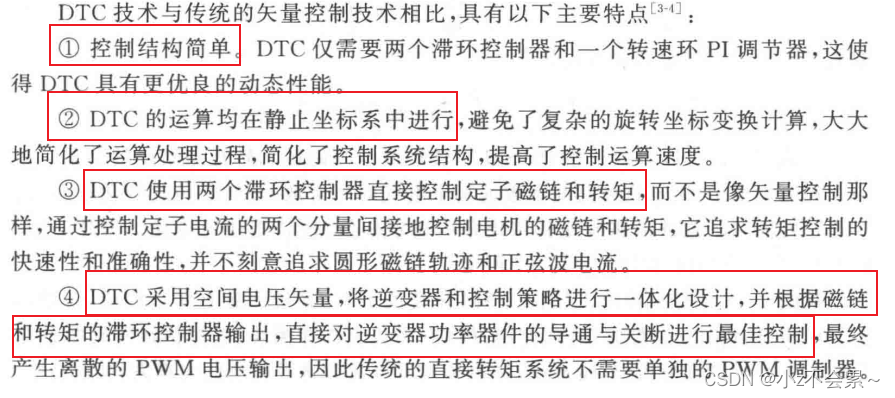
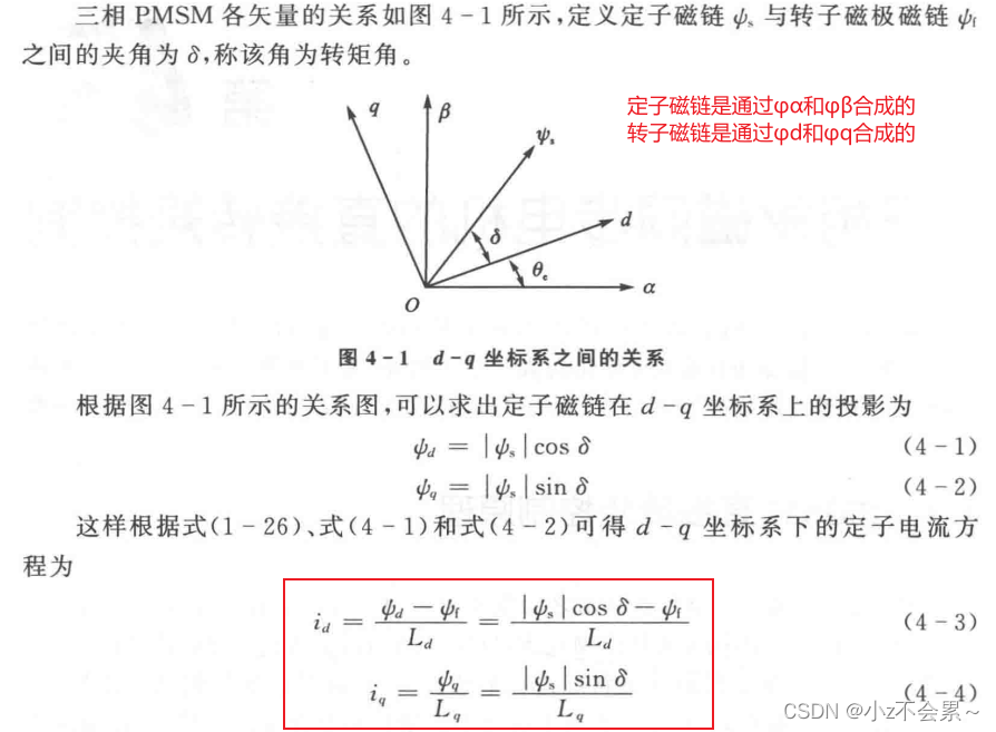
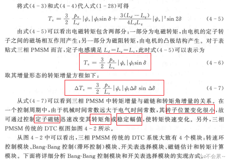
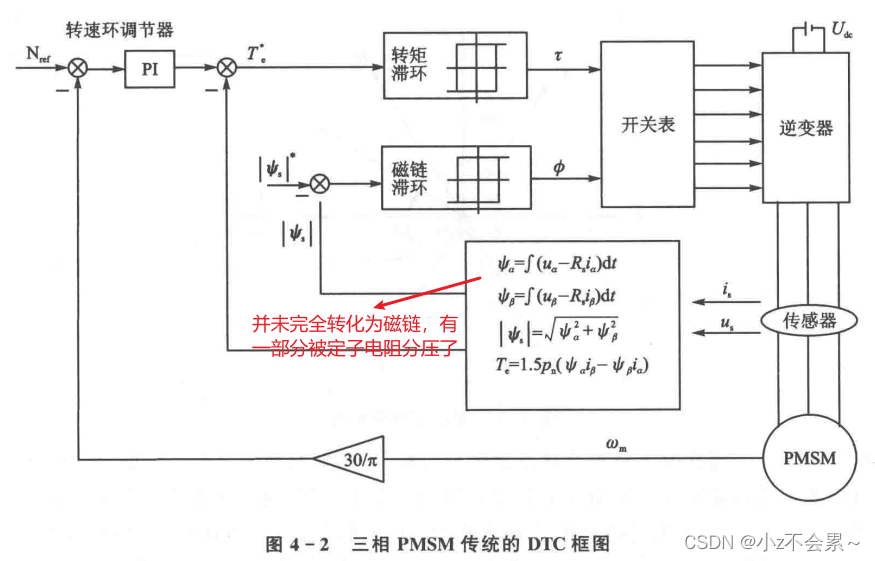
自己的理解:直接转矩控制是通过调节两个量来改变电机速度,一个是定子磁链幅值,一个是电磁转矩。定子磁链幅值属于标量,当这个值确定之后,相当于确定了磁链圆的半径,通过动态调节 i α , i β i_alpha,i_beta iα,iβ的值,来维持磁链 ψ s psi _s ψs幅值不变,直接转矩控制是将动态坐标系直接变为静态坐标系,若把它想象成一个动态坐标系的话,在调节 i α , i β i_alpha,i_beta iα,iβ的过程中,磁链矢量的方向是变化的,这就会导致转矩角的变化,从而影响电磁转矩的大小,所以需要根据速度反馈来动态调节电磁转矩的大小,相当于固定住定子磁链的大小,来直接控制电磁转矩,从而控制电机速度。
2 磁链和转矩控制原理
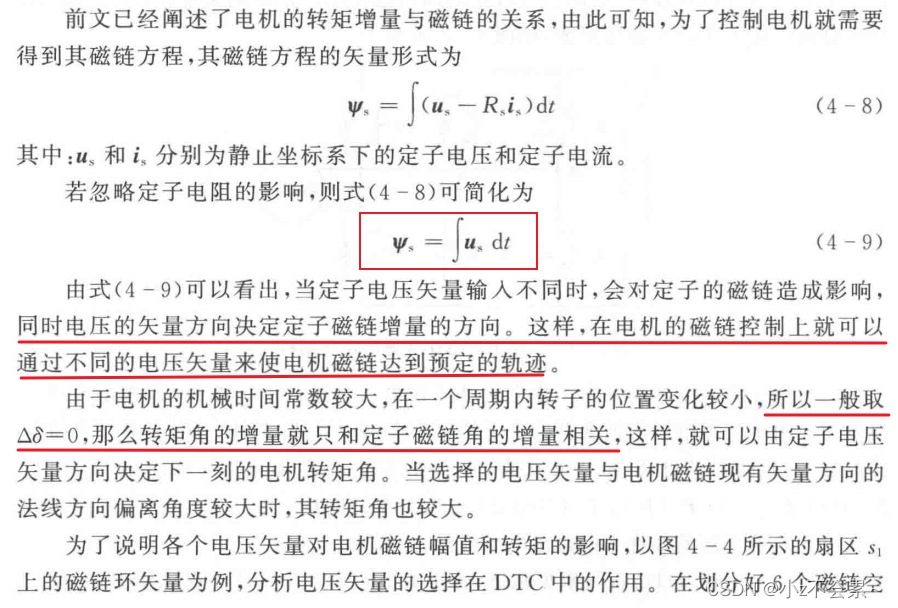
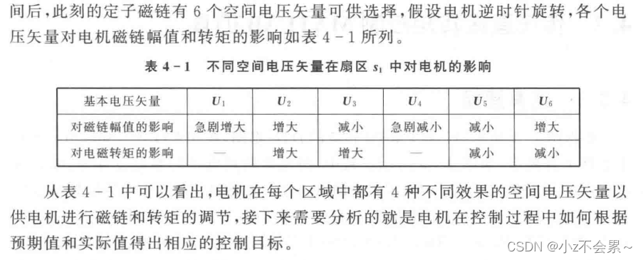
3 直接转矩控制开关表的选择
由于袁雷老师书中的代码和实际推导不太一样,这里按照其他资料所述过程推导。
part 1
通过反馈获得
u
a
b
c
,
i
a
b
c
u_{abc},i_{abc}
uabc,iabc后,根据逆Clark变换得到
u
α
,
u
β
u_alpha,u_beta
uα,uβ和
i
α
,
i
β
i_alpha,i_{beta}
iα,iβ,根据
d
ψ
s
d
t
=
u
s
−
R
s
i
s
frac{dpsi _s}{dt}=u_s-R_si_s
dtdψs=us−Rsis得:
ψ
a
=
∫
(
u
α
−
R
s
i
α
)
d
t
ψ
β
=
∫
(
u
β
−
R
s
i
β
)
d
t
psi _a=int{left( u_{alpha}-R_si_{alpha} right)}dt \ psi _{beta}=int{left( u_{beta}-R_si_{beta} right)}dt
ψa=∫(uα−Rsiα)dtψβ=∫(uβ−Rsiβ)dt
记
u
(
1
)
=
ψ
α
,
u
(
2
)
=
ψ
β
uleft( 1 right) =psi _{alpha},uleft( 2 right) =psi _{beta}
u(1)=ψα,u(2)=ψβ,设
u
r
e
f
1
=
u
(
1
)
,
u
r
e
f
2
=
−
u
(
1
)
+
3
u
(
2
)
,
u
r
e
f
3
=
−
u
(
1
)
−
3
u
(
2
)
u_{ref1}=uleft( 1 right) ,u_{ref2}=-uleft( 1 right) +sqrt{3}uleft( 2 right) ,u_{ref3}=-uleft( 1 right) -sqrt{3}uleft( 2 right)
uref1=u(1),uref2=−u(1)+3u(2),uref3=−u(1)−3u(2)
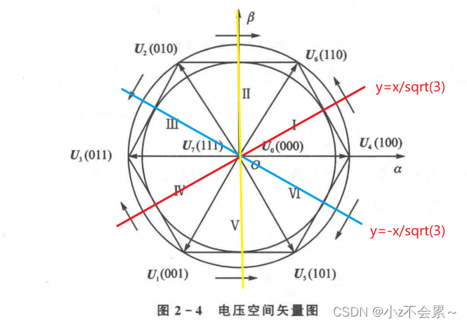
有: u r e f 1 > 0 u_{ref1}>0 uref1>0时有扇区:1,2,6, else:3,4,5
u r e f 2 > 0 u_{ref2}>0 uref2>0时有扇区:2,3,4 ,else:1,5,6
u r e f 3 > 0 u_{ref3}>0 uref3>0 时有扇区:4,5,6,else:1,2,3
定义A,B,C
| if u r e f 1 > 0 u_{ref1}>0 uref1>0 | if u r e f 2 > 0 u_{ref2}>0 uref2>0 | if u r e f 3 > 0 u_{ref3}>0 uref3>0 |
|---|---|---|
| A=0 | B=0 | C=0 |
| else | else | else |
| A=1 | B=1 | C=1 |
| end | end | end |
令 N = 4 A + 2 B + C N=4A+2B+C N=4A+2B+C
则 N N N与扇区的关系对应为
| N | 1 | 2 | 3 | 4 | 5 | 6 |
|---|---|---|---|---|---|---|
| sector | 2 | 6 | 1 | 4 | 3 | 5 |
例如:在扇区2时,A=0,B=0,C=1,N=1;
part2 选择最优开关矢量表
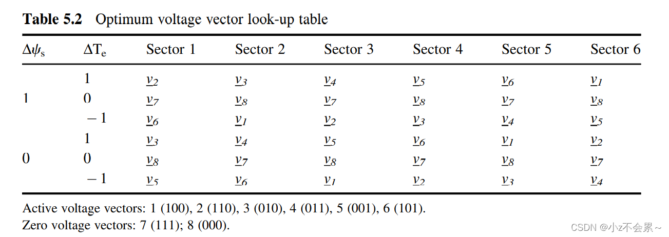
这里定义 u ( 1 ) = Δ ψ s , u ( 2 ) = Δ T e , u ( 3 ) = sec t o r uleft( 1 right) =varDelta psi _s,uleft( 2 right) =varDelta T_e,uleft( 3 right) =sec tor u(1)=Δψs,u(2)=ΔTe,u(3)=sector, u ( 1 ) u(1) u(1)取值0,1, u ( 2 ) u(2) u(2)取值-1,1
定义 x = u ( 1 ) + u ( 2 ) + 2 x=u(1)+u(2)+2 x=u(1)+u(2)+2,这样 u ( 1 ) , u ( 2 ) u(1),u(2) u(1),u(2)的4种组合下 x x x有4种取值1,2,3,4
以
x
x
x的取值为行,u(3)的取值为列,将look-up-table重新排列得
V
t
a
b
l
e
=
[
5
6
1
2
3
4
6
1
2
3
4
5
3
4
5
6
1
2
2
3
4
5
6
1
]
V_{table}=left[ begin{matrix}{} 5& 6& 1& 2& 3& 4\ 6& 1& 2& 3& 4& 5\ 3& 4& 5& 6& 1& 2\ 2& 3& 4& 5& 6& 1\ end{matrix} right]
Vtable=⎣
⎡563261431254236534164521⎦
⎤
最终应施加的电压矢量的编号为
V
t
a
b
l
e
(
x
,
u
(
3
)
)
V_{table}(x,u(3))
Vtable(x,u(3)).
s
w
i
t
c
h
i
n
g
s
t
a
t
e
=
V
t
a
b
l
e
(
x
,
u
(
3
)
)
switching space state=V_{table}(x,u(3))
switching state=Vtable(x,u(3))
这里咱们将表格5.2中
Δ
T
e
=
−
1
varDelta T_e=-1
ΔTe=−1,改成
Δ
T
e
=
0
varDelta T_e=0
ΔTe=0,这样做是为了避免sign()输出-1时,程序报错。这里需要重新定义x,
x
=
2
∗
u
(
1
)
+
u
(
2
)
+
1
x=2*u(1)+u(2)+1
x=2∗u(1)+u(2)+1,这样
u
(
1
)
,
u
(
2
)
u(1),u(2)
u(1),u(2)的4种组合下
x
x
x有4种取值1,2,3,4
以
x
x
x的取值为行,u(3)的取值为列,将look-up-table重新排列得
V
t
a
b
l
e
∗
=
[
5
6
1
2
3
4
3
4
5
6
1
2
6
1
2
3
4
5
2
3
4
5
6
1
]
V_{table}^*=left[ begin{matrix}{} 5& 6& 1& 2& 3& 4\ 3& 4& 5& 6& 1& 2\ 6& 1& 2& 3& 4& 5\ 2& 3& 4& 5& 6& 1\ end{matrix} right]
Vtable∗=⎣
⎡536264131524263531464251⎦
⎤
4 仿真
整体控制框图
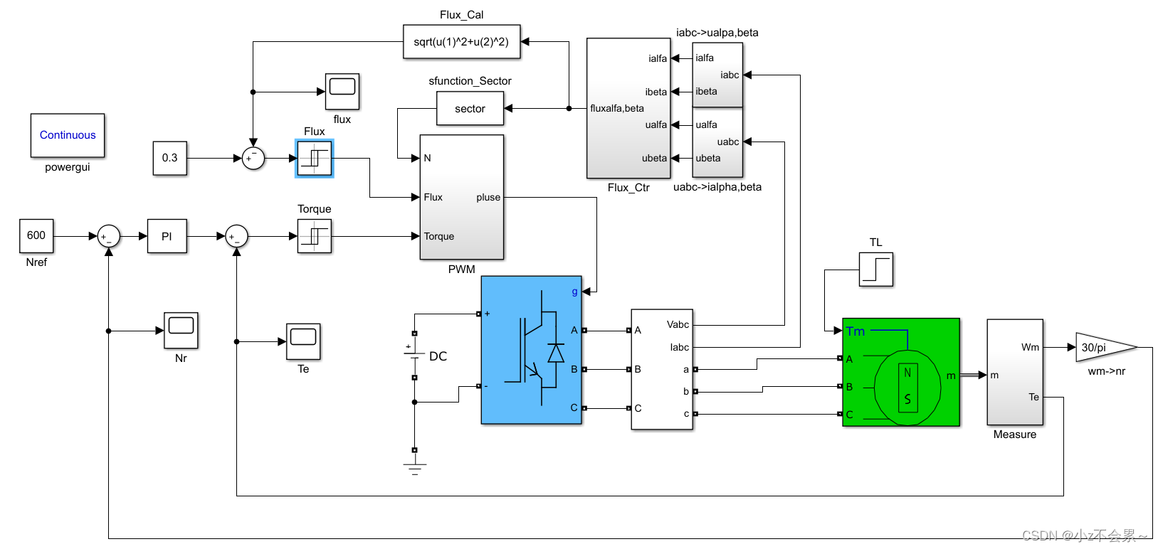
扇区选择程序sector.m
这个元件采用的是S-function
function [sys,x0,str,ts] = sector(t,x,u,flag)

% The following outlines the general structure of an S-function.
%
switch flag,   %判断flag,看当前处于哪个状态

  %%%%%%%%%%%%%%%%%%
  % Initialization %
  %%%%%%%%%%%%%%%%%%
  case 0,
  [sys,x0,str,ts]=mdlInitializeSizes;
  %%%%%%%%%%%
  % Outputs %
  %%%%%%%%%%%
  case 3,
    sys=mdlOutputs(t,x,u);
  case {2,4,9},
    sys=[];

  %%%%%%%%%%%%%%%%%%%%
  % Unexpected flags %
  %%%%%%%%%%%%%%%%%%%%
  otherwise
    error(['Unhandled flag = ',num2str(flag)]);

end

% end sfuntmpl

%
%=============================================================================
% mdlInitializeSizes
% Return the sizes, initial conditions, and sample times for the S-function.
%=============================================================================
%
function [sys,x0,str,ts]=mdlInitializeSizes

%
% call simsizes for a sizes structure, fill it in and convert it to a
% sizes array.
%
% Note that in this example, the values are hard coded.  This is not a
% recommended practice as the characteristics of the block are typically
% defined by the S-function parameters.
%
sizes = simsizes; %用于设置参数的结构体用simsizes来生成

sizes.NumContStates  = 0; %连续状态变量的个数
sizes.NumDiscStates  = 0; %离散状态变量的个数
sizes.NumOutputs     = 1; %输出变量的个数
sizes.NumInputs      = 2; %输入变量的个数
sizes.DirFeedthrough = 1; %是否存在反馈
sizes.NumSampleTimes = 1; %采样时间个数,至少是一个

sys = simsizes(sizes); %设置完后赋给sys输出
x0  = [];  %状态变量设置为空,表示没有状态变量
str = [];
ts  = [-1 0]; %采样周期设为0表示是连续系统,-1表示采用当前的采样时间

% end mdlInitializeSizes

%
%=============================================================================
% mdlOutputs
% Return the block outputs.
%=============================================================================
%
function sys=mdlOutputs(t,x,u)
if(u(1)==0)
    N=1;    %如果输入值为0,电压参考量在第一扇区
else
    a1=u(1);
    b1=u(1)*(-0.5)+(sqrt(3)/2)*u(2); %%根据文章的计算公式得到
    c1=u(1)*(-0.5)-(sqrt(3)/2)*u(2);
    if a1>0
        a=0;
    else
        a=1;
    end
    if b1>0
        b=0;
    else
        b=1;
    end
    if c1>0
        c=0;
    else
        c=1;
    end
    N=4*a+2*b+c; %扇区计算
end
Sector_table=[2 6 1 4 3 5];
sys=Sector_table(N);

% end mdlOutputs
脉冲生成程序PMSM_switch.m
function [sys,x0,str,ts] = PMSM_switch(t,x,u,flag)

% The following outlines the general structure of an S-function.
%
switch flag, %判断flag,看当前处于哪个状态

  %%%%%%%%%%%%%%%%%%
  % Initialization %
  %%%%%%%%%%%%%%%%%%
  case 0,
    [sys,x0,str,ts]=mdlInitializeSizes;
  %%%%%%%%%%%
  % Outputs %
  %%%%%%%%%%%
  case 3,
    sys=mdlOutputs(t,x,u);
  case {2,4,9},
    sys=[];

  %%%%%%%%%%%%%%%%%%%%
  % Unexpected flags %
  %%%%%%%%%%%%%%%%%%%%
  otherwise
    error(['Unhandled flag = ',num2str(flag)]);

end

%=============================================================================
% mdlInitializeSizes
% Return the sizes, initial conditions, and sample times for the S-function.
%=============================================================================
%
function [sys,x0,str,ts]=mdlInitializeSizes

%
% call simsizes for a sizes structure, fill it in and convert it to a
% sizes array.
%
% Note that in this example, the values are hard coded.  This is not a
% recommended practice as the characteristics of the block are typically
% defined by the S-function parameters.
%
sizes = simsizes;%用于设置参数的结构体用simsizes来生成

sizes.NumContStates  = 0;%连续状态变量的个数
sizes.NumDiscStates  = 0; %离散状态变量的个数
sizes.NumOutputs     = 1; %输出变量的个数
sizes.NumInputs      = 3; %输入变量的个数
sizes.DirFeedthrough = 1; %是否存在反馈
sizes.NumSampleTimes = 1; %采样时间个数,至少是一个

sys = simsizes(sizes);%设置完后赋给sys输出
x0  = [];%状态变量设置为空,表示没有状态变量
str = [];
ts  = [-1 0]; %采样周期设为0表示是连续系统,-1表示采用当前的采样时间

% end mdlInitializeSizes

%
%=============================================================================
% mdlOutputs
% Return the block outputs.
%=============================================================================
%
function sys=mdlOutputs(t,x,u)
 %%根据文章的表格计算得到
% V_Table=[2 4 6 1 3 5;4 1 5 2 6 3;3 6 2 5 1 4 ;5 3 1 6 4 2];
V_Table=[5 6 1 2 3 4;3 4 5 6 1 2;6 1 2 3 4 5;2 3 4 5 6 1];
% x=2*u(1)+u(2)+1;
x=2*u(1)+u(2)+1;
sector=u(3);
sys=V_Table(x,sector);

% end mdlOutputs
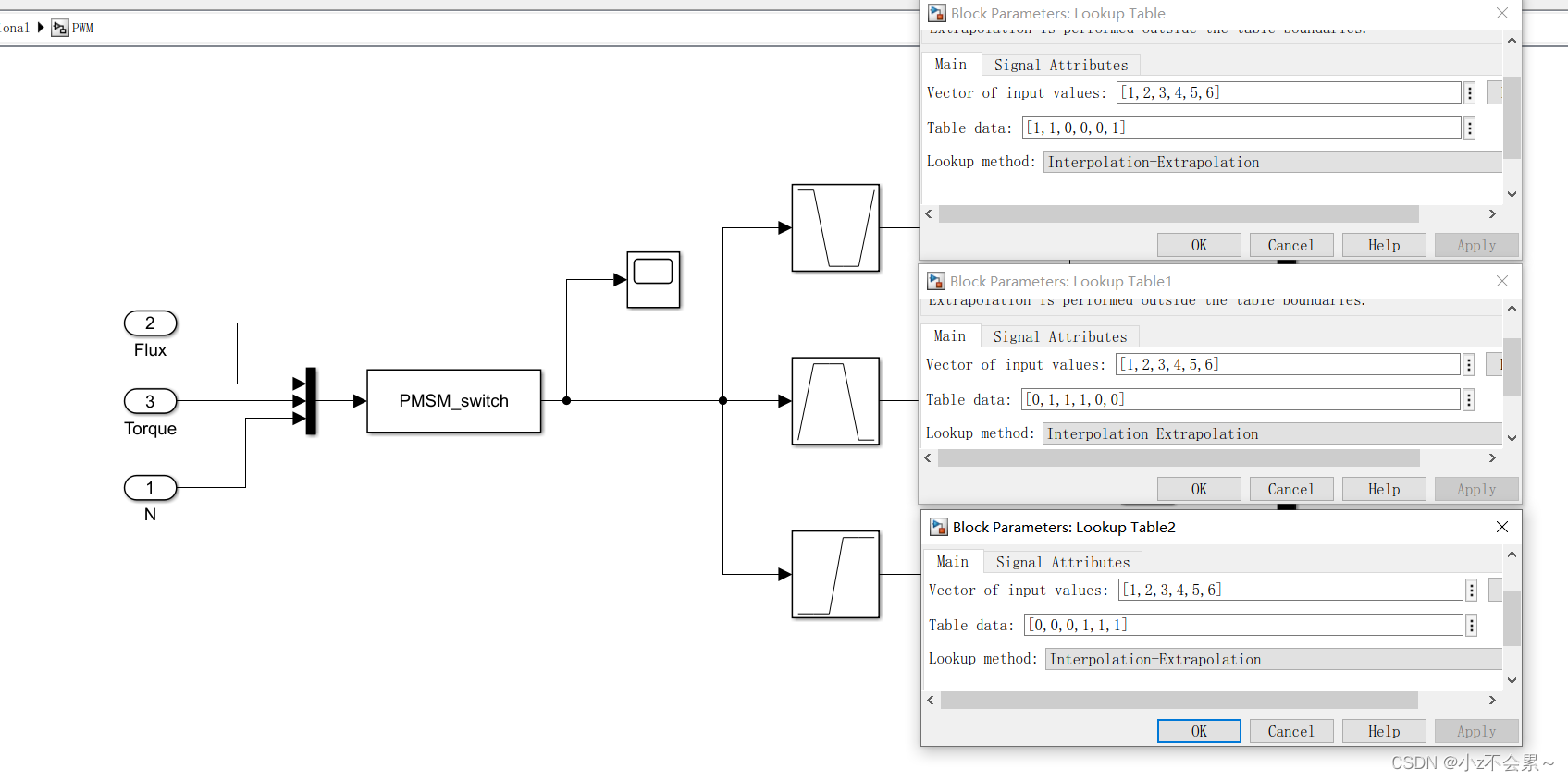
lookup设置
转速环PI调节器的仿真模型

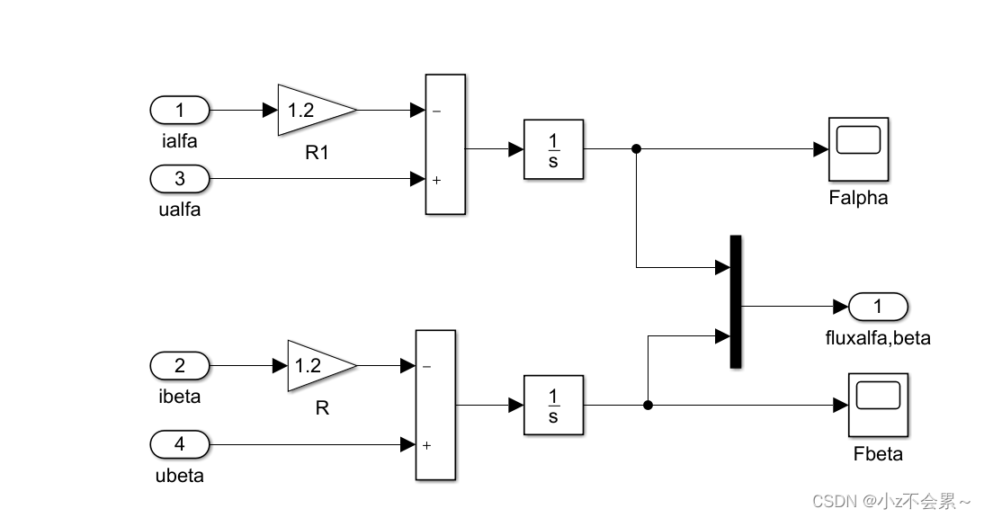
定子磁链计算的仿真模型
仿真结果分析
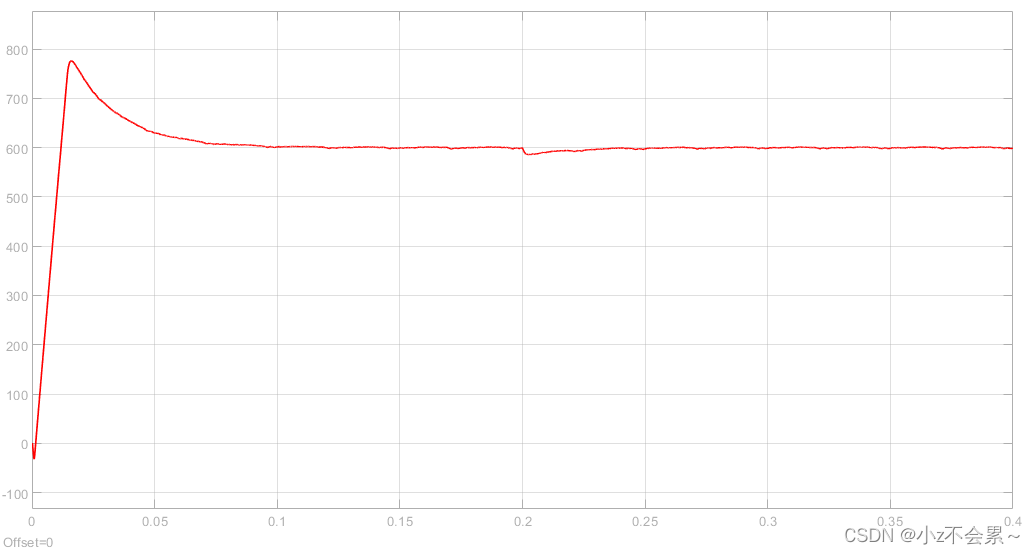
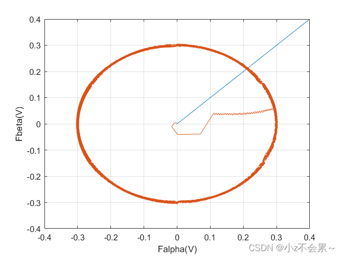
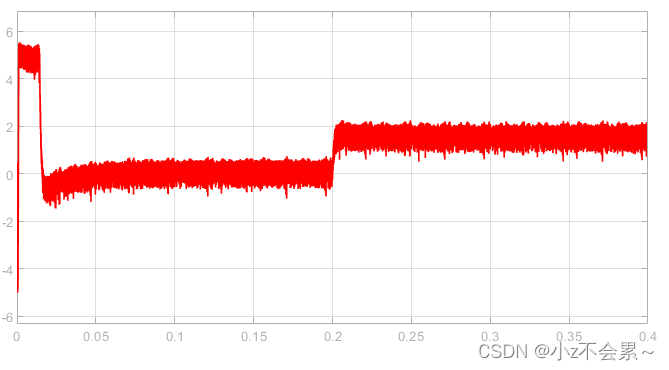
为了验证所搭建仿真模型的正确性,仿真条件设置为:磁链参考设定值为 ∣ ψ s ∣ ∗ = 0.3 W b left| psi _s right|^*=0.3Wb ∣ψs∣∗=0.3Wb,参考转速设定为 N r e f = 600 r / m i n N_{ref}=600 r/min Nref=600r/min,初始时刻负载转矩 T L = 0 N ⋅ m T_L=0Ncdot m TL=0N⋅m,在 t = 0.2 s t=0.2s t=0.2s时负载转矩 T L = 1.5 N ⋅ m T_L=1.5 Ncdot m TL=1.5N⋅m,仿真结果如下所示。
转速环参数设置: k p = 0.1 , k i = 5 k_p=0.1,k_i=5 kp=0.1,ki=5。
转速 N r N_r Nr的变化曲线
磁链相图的变化曲线
电磁转矩 T e T_e Te的变化曲线
实际磁链 ∣ ψ s ∣ left| psi _s right| ∣ψs∣的变化曲线
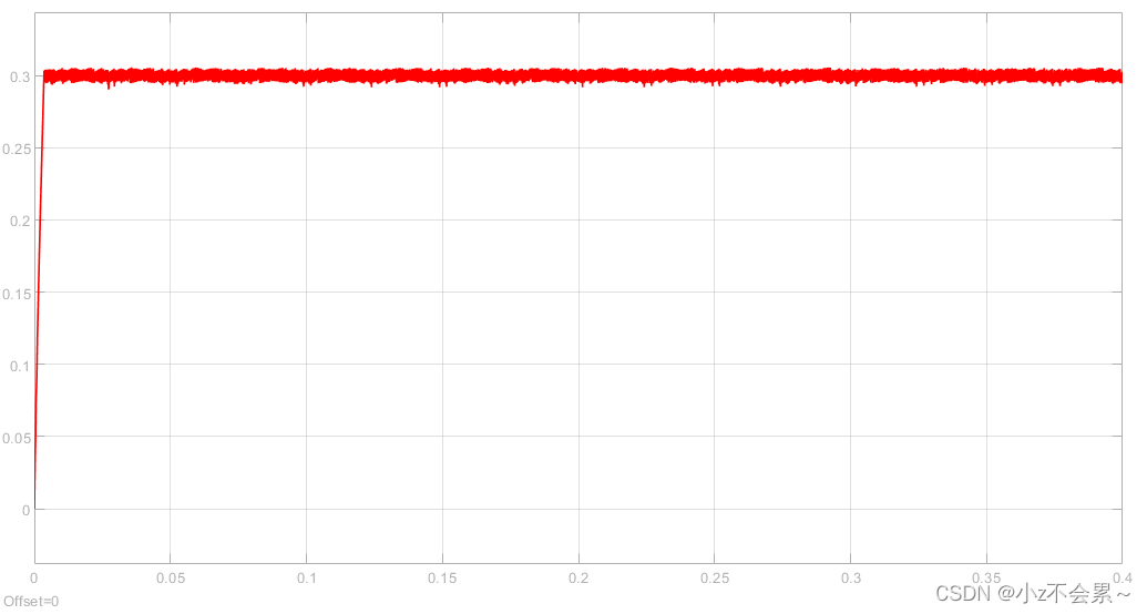
从以上仿真结果可以看出,当电机从零速上升到参考转速600r/min时,虽然开始时电机转速有一些超调量,但仍然具有较快的动态响应速度,并且在
t
=
0.2
s
t=0.2s
t=0.2s时突加负载转矩
T
L
=
1.5
N
⋅
m
T_L=1.5Ncdot m
TL=1.5N⋅m,电机也能快速恢复到给定参考转速值,能够满足实际电机控制性能的需要。然而观察电磁转矩波形,发现波动较大,这在实际工程中要避免。
本文内容摘自袁雷的《现代永磁同步电机控制原理及MATLAB仿真》的第四章,自己做了一下PMSM双闭环DTC的仿真,这里做一个记录,方便以后查阅,该控制方案对实际工程也有一定的启发,感谢大家的阅读!!!_
最后
以上就是正直月光最近收集整理的关于PMSM直接转矩控制(DTC)的全部内容,更多相关PMSM直接转矩控制(DTC)内容请搜索靠谱客的其他文章。


发表评论 取消回复