Verilog的QPSK调制实现
QPSK调制一般采用两种方式:(1)调相法 (2)四相位选择法
一、调相法
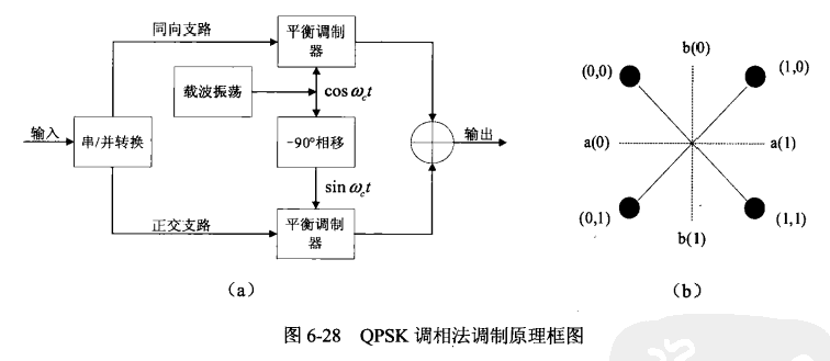
利用三段式状态机,实现由输入信号输出 两路正交相位调制输出
`timescale 1ns / 1ps
//
// Company:
// Engineer:
//
// Create Date: 2019/07/27 13:23:19
// Design Name:
// Module Name: QPSK
// Project Name:
// Target Devices:
// Tool Versions:
// Description:
//
// Dependencies:
//
// Revision:
// Revision 0.01 - File Created
// Additional Comments:
//
//


module QPSK(clk,rst_n,din,valid_in,out_real,out_imag,valid_out);

 input clk;
 input rst_n;
 input valid_in;     //控制信号输入
 input din;          //输入信号
 output out_real;    // 实部输出
 output out_imag;    //虚部输出
 output valid_out;   //已调制后信号输出的标志

 reg[15:0] out_real;
 reg[15:0] out_imag;
 reg       valid_out;

 reg[1:0]  temp;
 reg[1:0]  state;
 reg[1:0]  nextstate;

 parameter IDLE=2'b00,state1=2'b01,state2=2'b10,
           ONE=16'h0fff;

 always@(posedge clk)
   begin
     if(!rst_n)
       state <= IDLE;
     else
       state <= nextstate;
   end

  always@(* )
    begin
      if(!rst_n)
        nextstate <= IDLE;
      else
        begin
              case(state)
              	 IDLE:
              	   begin
              	     if(valid_in == 1'b1)
                      nextstate <= state1;
                     else
              	  	   nextstate <= state;
                   end

              	 state1:
              	  begin
              	  	 if(valid_in == 1'b1)
              	 	   nextstate <= state2;
              	 		 else
              	  	   nextstate <= state;
              	  end

                state2:
              	  begin
              	  	 if(valid_in == 1'b1)
              	 	   nextstate <= state1;
              	     else
              	  	   nextstate <= state;
              	  end
                default:nextstate <= IDLE;
              endcase
            end
        end


 always@(posedge clk)
   begin
     if(!rst_n)
       temp <= 2'b00;
     else
       begin
         if(valid_in)
            temp <= {temp[0],din};
         else
             temp <= temp;
       end
   end

  always@(posedge clk)
   begin
     if(!rst_n)
       begin
         out_real <= 16'b0000_0000_0000_0000;
         out_imag <= 16'b0000_0000_0000_0000;
       end
     else
       begin
       	 if(state==state2)
       	   case(temp)

           2'b00:
             begin
                 out_real <= ONE;
                 out_imag <= ONE;
             end

           2'b01:
             begin
                 out_real <= ~ONE;
                 out_imag <= ONE;
             end

           2'b11:
             begin
                 out_real <= ~ONE;
                 out_imag <= ~ONE;
             end

           2'b10:
             begin
                 out_real <= ONE;
                 out_imag <= ~ONE;
             end

           default:
             begin
                 out_real <= 16'h0000;
                 out_imag <= 16'h0000;
             end
           endcase
         else
           begin
             out_real <= 16'b0000_0000_0000_0000;
             out_imag <= 16'b0000_0000_0000_0000;
           end
       end
     end

 always@(posedge clk)
   begin
     if(!rst_n)
       begin
         valid_out <= 1'b0;
       end
     else
       begin
       	 if(state==state2)
           valid_out <= 1'b1;
         else
           begin
             valid_out <= 1'b0;
           end
       end
    end
endmodule
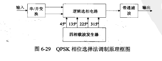
二、四相位选择法
module qpsk(clk,rst,x,y)
input clk,rst;
input x; //系统输入信号:每4个∞1k周期输入一个x的值
output y; /QPSK调制输出信号:在8个ck周期内按bit输出
reg [2: 0]count //计数器
reg [1: 0] xreg; //输入信号的中间寄存器
reg [1: 0] yreg;
reg[3:0] carriers;//4路载波信号
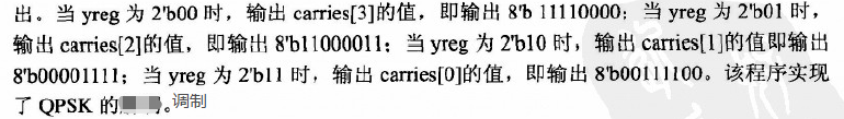
/实现QPSκ解调
assign y =(yreg == 2'b00)? carriers [3]:
(yreg == 2'b01)? carriers [2]:
(yreg == 2' b10)? carriers [1]:
(yreg == 2 b11)? carriers [0] :0;
//完成计数器,从而对模块时钟分频
always @(posedge clk or negedge rst)
if(!rst)
count <= 3'b000;
else
count <= count +1
//寄存输入:每4个c1k周期,将输入x寄存到xreg中
always @(posedge clk or negedge rst)
if(!rst)
xreg <= 2'b00;
else
if(count[1:0]==2'b11)
xreg <= {xreg[0],x};
else
xreg <= xreg;
//产生载波信号并且每8个周期将奇存器xeg的值送到yreg中,供后面判断输出
always @(posedge clk or negedge rst)
if(!rst)
begin
carriers <= 4'b000;
yreg <= 2'b00;
end
else
begin
case(count)
3'b000:begin
yreg <= xreg;
carriers <= 4'b1100;
end
3'b010:carriers <= 4'b1001;
3'b100:carriers <= 4'b0011;
3'b110:carriers <= 4'b0110;
default:carriers <= carriers;
endcase
end
endmodule
参考资料:
1、基于Verilog HDL的通信系统设计 陈曦
最后
以上就是完美火最近收集整理的关于Verilog学习笔记 (四)QPSK调制实现 Verilog的QPSK调制实现的全部内容,更多相关Verilog学习笔记内容请搜索靠谱客的其他文章。
本图文内容来源于网友提供,作为学习参考使用,或来自网络收集整理,版权属于原作者所有。


发表评论 取消回复