1、前言:续接上一章MATLAB简单机器人视觉控制仿真(1)
一方面,由于直接利用robot toolbox 工具箱的正逆解函数:ikine()和fkine()去做控制是在求解过程中出现红色字体的警告信息,且在使用过程中都直接调用fkine()求逆解,打开它又不太了解具体编写细节。还不如自己编写正逆运动学方程,当然这个也是直接来源于正逆运动学和参看(http://blog.sina.com.cn/s/blog_131fa47b20102whij.html,机器人学导论中第三章和第四章中的内容)。
另一方面,同样针对上一章提出的问题---提高速度。修改了上一节代码,感觉有些解决了卡顿的问题,所以做个记录。
2、代码:(添加了视频预览窗口和编写逆解求解过程,有些参数随意取的,有些粗糙了 :( )
clear ;
clc;
L1=Link([0       0.4      0.025    pi/2      0     ]);
L2=Link([pi/2    0        0.56     0         0     ]);
L3=Link([0       0        0.035    pi/2      0     ]);
L4=Link([0       0.515    0        pi/2      0     ]);
L5=Link([pi      0        0        pi/2      0     ]);
L6=Link([0       0.08     0        0         0     ]);
t3r=[L1;L2;L3;L4;L5;L6];
bot=SerialLink(t3r,'name','Useless');
a = imaqhwinfo;
%[camera_name, camera_id, format] = getCameraInfo(a);
 f1=figure;
% set (gcf,'Position',[200,200,400,500], 'color','w');
 f2=figure;
% Capture the video frames using the videoinput function
% You have to replace the resolution & your installed adaptor name.
vid = videoinput('winvideo',1,'YUY2_640x480');
%sls=videoinput('winvideo',1)
% Set the properties of the video object

set(vid,'TriggerRepeat',Inf);
vid.TriggerRepeat= Inf;%持续不断获取图像
set(vid, 'ReturnedColorspace', 'rgb')%设置颜色空间为RGB
vid.FrameGrabInterval = 1;%每隔5帧取一幅图像
preview(vid);%预览窗口

%start(vid)

%start the video aquisition here

n=50;
% Set a loop that stop after 100 frames of aquisition
while(vid.FramesAcquired<=500)

    % Get the snapshot of the current frame
    data=getsnapshot(vid);
    data=imresize(data,[400,500]);

    % Now to track red objects in real time
    % we have to subtract the red component
    % from the grayscale image to extract the red components in the image.
    diff_im = imsubtract(data(:,:,1), rgb2gray(data));
    %Use a median filter to filter out noise
    diff_im = medfilt2(diff_im, [3 3]);
    % Convert the resulting grayscale image into a binary image.
    diff_im = im2bw(diff_im,0.18);

    % Remove all those pixels less than 300px
    diff_im = bwareaopen(diff_im,300);

    % Label all the connected components in the image.
    bw = bwlabel(diff_im, 8);

    % Here we do the image blob analysis.
    % We get a set of properties for each labeled region.
    stats = regionprops(logical(bw), 'BoundingBox', 'Centroid');
    figure(f1)
    imshow(data)
    for object = 1:length(stats)
        bb = stats(object).BoundingBox;
        bc = stats(object).Centroid;
        rectangle('Position',bb,'EdgeColor','g','LineWidth',3)
        a=text(bc(1)+15,bc(2), strcat('X: ', num2str(round(bc(1))), '    Y: ', num2str(round(bc(2)))));
        set(a, 'FontName', 'Arial', 'FontWeight', 'bold', 'FontSize', 14, 'Color', 'blue');
 Px=bc(1);
 Py=bc(2);
 Pz=2*bc(1)+3*bc(2);
        a2 = 650;
        a3 = 0;
        d3 = 190;
        d4 = 600;
         K = (Px^2+Py^2+Pz^2-a2^2-a3^2-d3^2-d4^2)/(2*a2);
 theta1 = (atan2(Py,Px)-atan2(d3,sqrt(Px^2+Py^2-d3^2)));
                c1 = cos(theta1);
                s1 = sin(theta1);
                theta3 = (atan2(a3,d4)-atan2(real(K),real(sqrt(a3^2+d4^2-K^2))));
                c3 = cos(theta3);
                s3 = sin(theta3);
                t23 = atan2((-a3-a2*c3)*Pz-(c1*Px+s1*Py)*(d4-a2*s3),(a2*s3-d4)*Pz+(a3+a2*c3)*(c1*Px+s1*Py));
                theta2 = (t23 - theta3);
                c2 = cos(theta2);
                s2 = sin(theta2);
                s23 = ((-a3-a2*c3)*Pz+(c1*Px+s1*Py)*(a2*s3-d4))/(Pz^2+(c1*Px+s1*Py)^2);
                c23 = ((a2*s3-d4)*Pz+(a3+a2*c3)*(c1*Px+s1*Py))/(Pz^2+(c1*Px+s1*Py)^2);
                theta4 = atan2(s1+c1,c1*c23-s1*c23 + s23);
                c4 = cos(theta4);
                s4 = sin (theta4);
                s5 = -((c1*c23*c4+s1*s4)+(s1*c23*c4-c1*s4)-(s23*c4));
                c5 = (-c1*s23)+(-s1*s23)+(-c23);
                theta5 = atan2(s5,c5);
                s6 = (c1*c23*s4-s1*c4)-(s1*c23*s4+c1*c4)+(s23*s4);
                c6 = ((c1*c23*c4+s1*s4)*c5-c1*s23*s5)+((s1*c23*c4-c1*s4)*c5-s1*s23*s5)-(s23*c4*c5+c23*s5);
                theta6 = atan2(s6,c6);
   q=[theta1 theta2 theta3 theta4 theta5 theta6];
 figure(f2)
 bot.plot(q);
    end

 end
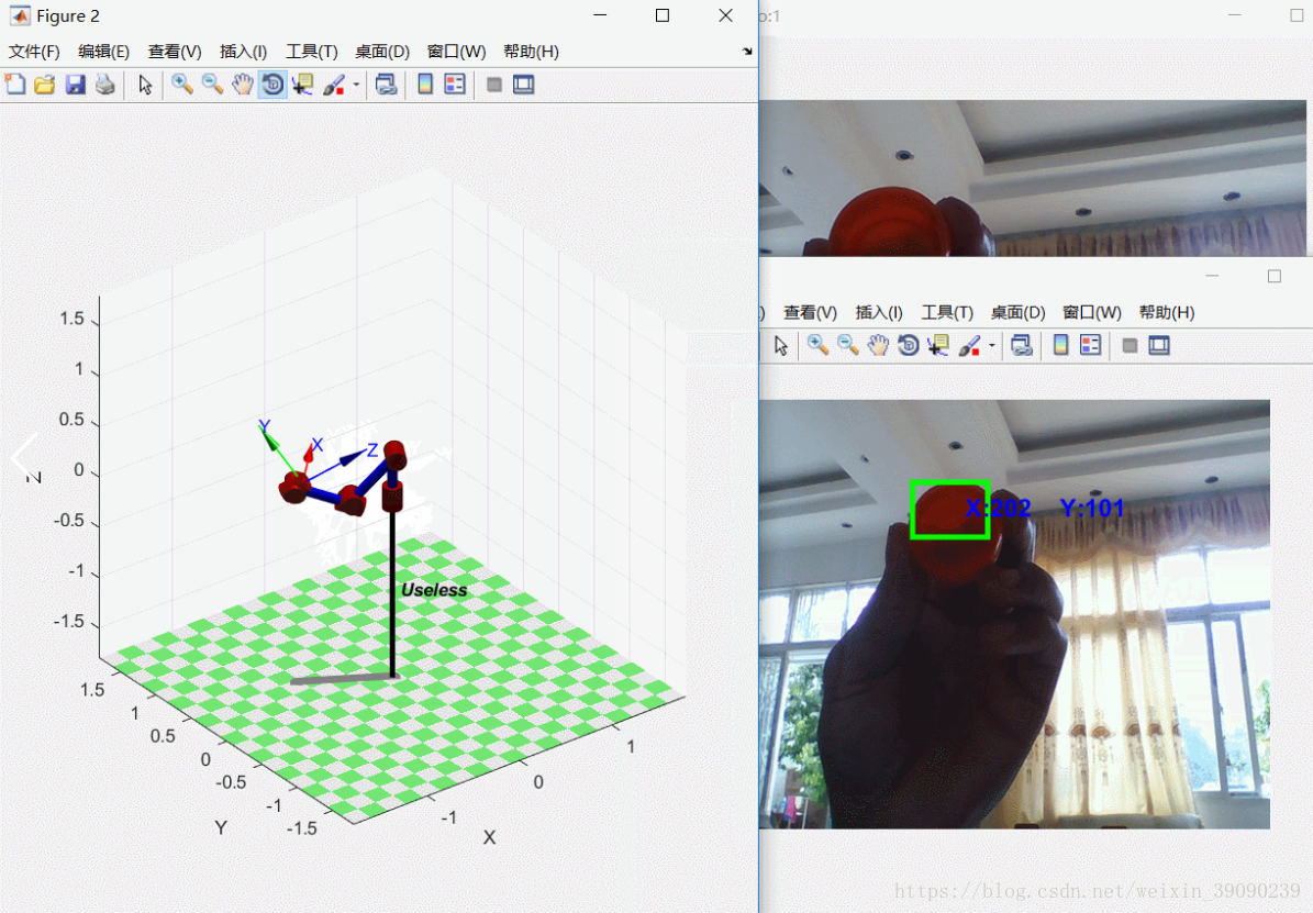
3、效果:左右移动带红色的物体,机器人模型跟着左右移动(有时候会因求解不满足---停止)

最后
以上就是鲜艳雪碧最近收集整理的关于MATLAB简单机器人视觉控制(仿真2)的全部内容,更多相关MATLAB简单机器人视觉控制(仿真2)内容请搜索靠谱客的其他文章。
本图文内容来源于网友提供,作为学习参考使用,或来自网络收集整理,版权属于原作者所有。


发表评论 取消回复