整体概览
物联网 IOT 的概念已经炒了很多年了,抛开产品及其本身用到的技术而言,在单片机开发领域它会涉及到开发环境、硬件平台、编程框架以及操作系统等等几大方面。国内各大厂家争先也出了自己的物联网操作系统,比如:华为鸿蒙(liteos)、阿里 AliOS Things、腾讯 TinyOS 、RT-Thread OS 等等,至于框架以及操作系统相结合的代表作有 ZLG 的 AMetal + AWorks ,还有 ARM 官方的 mbed os 框架平台现在也是越来越流行了。提到开源硬件平台,基本都能提到 arduino、NodeMCU 、ESP32 和树莓派这几个,基于这些平台有太多极客、黑客们各种好玩的东西了。说到这里,想必大家就会自然发问:那玩转这些东西是不是得要有一个统一的集成开发环境呢?好在 PlatformIO 这个工具软件在合适的时候诞生了,它几乎包含了以上提到的所有内容,就是这么牛的存在。那今天就一起来揭开 PlatformIO 的面纱,在这个集成环境中使用 MM32F3273G9P MB-039 开发板来做开发调试。以下几部分为本次分享的要点:
- PlatformIO 简介
- 将 MM32F3273G9P 集成到 VS-Code PlatformIO 中
- 后续待完成的集成要点
- 参考链接
- 附件内容
一、PlatformIO 简介
PlatformIO (https://docs.platformio.org/en/latest/what-is-platformio.html)是一个用于物联网开发的开源生态系统。它提供跨平台的开发环境和统一的调试器,是一个跨平台的代码构建工具和库管理工具,支持远程单元测试和固件更新等等功能,还支持像 Arduino 和 MBED 这样的开源框架及硬件平台,可以抛开 Arduino IDE 和 ARM mbed ide 了。它是独立于电脑平台运行的,只依赖于 python,所以在 macOS、linux 和 windows 上都能完美适配,也就是说 PlatformIO 的工程从一个电脑很容易迁移到另一个电脑,只需要拷贝再使用 PlatformIO 就能完美打开,不管团队中的成员使用什么操作系统 PlatformIO 可以让工程共享变得异常简单。 此外, PlatformIO 不仅可以在笔记本和台式机上运行,同样可以运行在没有显示桌面的服务器。使用它作开发时工作流程可以简化,首先用户在 “platformio.ini” (工程配置文件) 中指定开发平台(开发板),接着根据配置文件中的开发板(一个工程可以配置多个开发板),PlatformIO 会自动下载并安装对应的交叉编译链工具以及调试工具.,最后用户编写代码,PlatformIO 来保证所有指定开发板的编译、调试和上传工作即可完成所有开发工作。
熟悉 VS-Code 的伙伴们更加习惯以 PlatformIO 插件的形式做集成,VS-Code + PlatformIO 的环境有以下一些特性:
- PIO 统一的调试器,可以零配置的对支持硬件调试的的嵌入式开发板进行调试工作,调试器支持很多的架构和开发平台
- 跨平台的代码构建系统对系统软件没有额外的依赖: 600+ 嵌入式开发板, 30+ 开发平台, 15+ 框架
- C/C++ 智能代码补全,语法检查,快速重构以及代码跳转满足快速专业的开发需求
- VSCode 提供多工程和文件管理的支持和统一而流畅的使用体验,并且支持多种色彩主题,总有您喜欢和适合您的
- 内建的终端支持 PlatformIO Core 命令行工具,并且支持强大的串口调试器
- 除了支持大约 600+ 个开发板和市面上流行的支持跨平台的 30 个硬件平台,同时,PlatformIO 还提供大量的开发库,目前超过了 6000 个,为了方便新手入门开发,他们也同样提供代码例程
- 可以通过命令行形态存在,也可以嵌入到其它主流的编辑环境中
- 获得过 2015/16 IOT 年度最佳开发软件和工具奖 提名
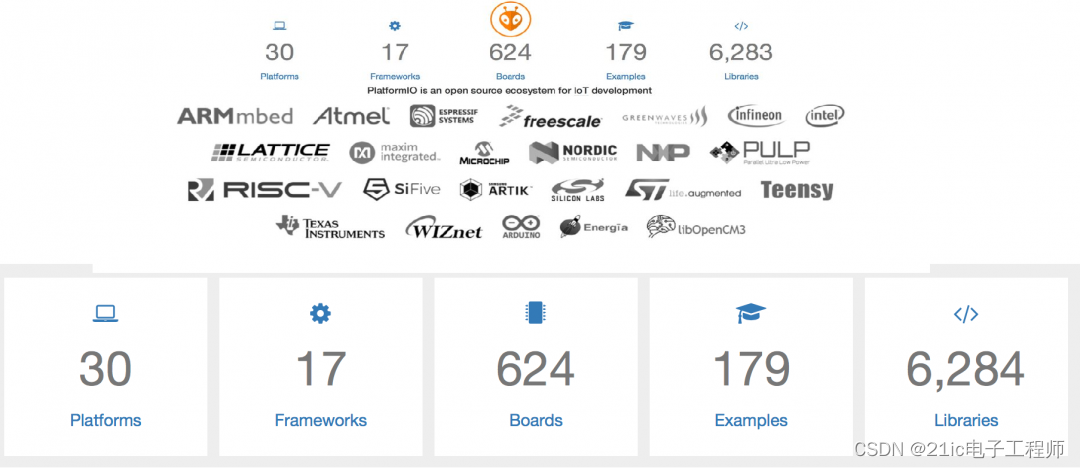
那是不是就可以愉快地在灵动微 MCU 上耍起来了呢?可能没那么简单。![]() 下面讲讲适配过程。
下面讲讲适配过程。
二、将 MM32F3273G9P 集成到 VS-Code PlatformIO 中
在开发板和平台页未找到关于灵动微的任何信息,顺便再看了一下,国产 MCU 厂家中也只有 GD32 的是已经适配好了的,不愧为国产 32位 MCU 中的 NO.1 ,另外也看到很多 STM32 的板子。在熟悉一个新鲜东西的时候,往往是需要从易到难的这么一个适应过程,不然就容易从入门到放弃了,所以我选择先搭建好 STM32F103ZET6 这颗芯片的闪灯工程,熟悉好了整个过程后再去适配灵动微的。下面为详细步骤:
1. 在 VS-Code 插件中搜索 PlatformIO ,下载安装,有时候需要添加到可信任工作区中并且重启 VS-Code 。完成安装后,可以先熟悉一遍软件中每个按键/Tab页的含义,另外需要注意,前提是需要确保安装好了 Python 环境。
2. 在 PIO 的主页点击 New Project 新建一个工程,输入自己的工程名称并且选择好对应的开发板以及开发框架,这里选择 genericSTM32F103ZE 开发板和 CMSIS 框架,然后 Finish ,第一次加载需要下载配套的工具包(编译器、tool、CMSIS 框架包等等),等待全部下载好即可出现空白工程目录,我的依赖包下载路径自动选择为 “C:Usersyang3.platformiopackages”,新建的工程路径默认选择为了“C:Usersyang3DocumentsPlatformIOProjects”
3. 将原子的模板闪灯例程中的一些源文件拷贝到新建的空白工程下的 src 文件夹中,主要有 CORE、HARDWARE、STM32F10x_FWLib、SYSTEM 、main.c、
stm32f10x.h 、stm32f10x_conf.h 、stm32f10x_it.c 、stm32f10x_it.h 、system_stm32f10x.c 、system_stm32f10x.h 这些文件和文件夹,完成复制后整个工程目录结构如下: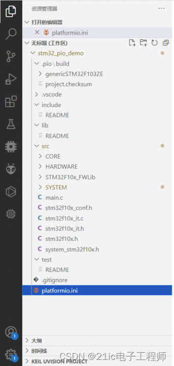
4. 改写 PIO 的工程配置文件 platformio.ini ,该文件位于根目录下,改写的代码如下:
; PlatformIO Project Configuration File

;

;   Build options: build flags, source filter

;   Upload options: custom upload port, speed and extra flags

;   Library options: dependencies, extra library storages

;   Advanced options: extra scripting

;

; Please visit documentation for the other options and examples

; https://docs.platformio.org/page/projectconf.html


[env:genericSTM32F103ZE]

platform = ststm32

board = genericSTM32F103ZE  ;实际为 MM32F3273_MB039

framework = cmsis


upload_protocol = jlink     ; 代码上传工具,

debug_tool  = jlink         ; debug工具

build_flags =               ; Build options

    -Isrc

    -Isrc/CORE

    -Isrc/HARDWARE/LED

    -Isrc/MM32F327x_FWLib/inc

    -Isrc/SYSTEM/DELAY

    -Isrc/SYSTEM/SYS

    -Isrc/SYSTEM/UART


    -D STM32F10X_HD         ; 定义全局宏

    -D USE_STDPERIPH_DRIVER
类似于 keil ,上面代码配置定义好了平台、板子、框架软件包、调试下载工具类型、用户头文件路径以及其它一些全局宏定义等等。
5. 需要知道,PIO 的集成编译器是依赖于 toolchain-gccarmnoneeabi 的,所以源码中的一些不适合 gcc 编译器的地方都得改正过来,最后编译即可,点击编译可以是通过下方的“√”,也可通过 PIO PROJECT TASKS 中的 Build Task 按键。
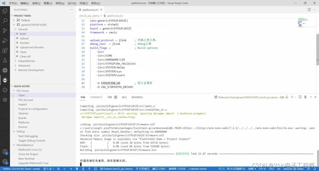
到这里已经很轻松地完成了 STM32F103 的示例工程导入,通过这一系列的操作,也已经熟悉了 PIO 的开发流程,那接下来就是要做替换了,由于使用的是 CMSIS 框架,与平台相关的外设驱动包改动不涉及框架支持包的重写,所以会稍微容易实现些。下面为替换步骤:
1. 通过查看 ststm32 平台包,熟悉整个 PIO 平台支持包的内容含义,明确要改写哪些文件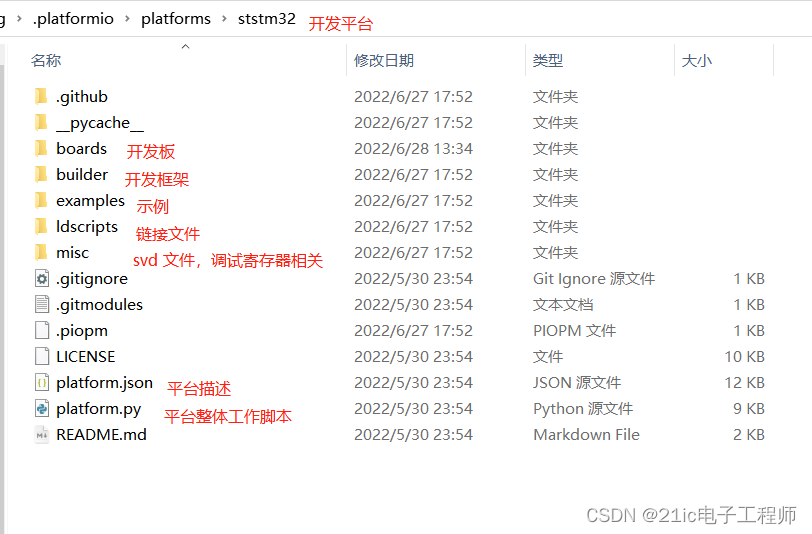
2. 由于开发板选择的是 genericSTM32F103ZE ,对应的文件为 genericSTM32F103ZE.json ,其中主要改写调试相关的选择为:
"debug": {

    "jlink_device": "MM32F3273G9P",

    "openocd_target": "stm32f1x",

    "svd_path": "MM32F327x.svd"

  },
特别注意,core 、 extra_flags 、mcu 、variant 等几项选择不能改写,否则会影响其它支持包的适配,关于 name 和 vendor 这2项是可以修改的,这个会直接体现在 PIO 主页新建工程时候的 board 选项显示中。
3. 在 misc - svd 中需要添加 MM32F327x.svd ,该文件可以通过灵动微官方的 keil pack 中获取到,该文件描述了芯片的寄存器,在后面调试时可以对照参阅,如果不替换那么就会显示错误的寄存器数据。
4. 此外,还需要对依赖的包做内容修改替换,这里只涉及到“packagesframework-cmsis-stm32f1”这个包,需要将 Include 文件夹下与芯片相关的头文件全部替换掉,以及 Source - Templates 下的 system_stm32f1xx.c 需要更改内容为 system_mm32f3270.c 中的,名称不改,Source - Templates - gcc 中的 startup_stm32f103xe.s 需要更改为 startup_mm32f3270_gcc.s 中的内容,名称不改 ,Source - Templates - gcc - linker 中的 STM32F103XE_FLASH.ld 同样按照 mm32f3273g9p 去做修改。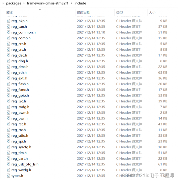
/// [url=home.php?mod=space&uid=288409]@file[/url]     SYSTEM_MM32.C

/// [url=home.php?mod=space&uid=187600]@author[/url]   AE TEAM

/// [url=home.php?mod=space&uid=247401]@brief[/url]    THIS FILE PROVIDES ALL THE SYSTEM FUNCTIONS.


/// @attention

///

/// THE EXISTING FIRMWARE IS ONLY FOR REFERENCE, WHICH IS DESIGNED TO PROVIDE

/// CUSTOMERS WITH CODING INFORMATION ABOUT THEIR PRODUCTS SO THEY CAN SAVE

/// TIME. THEREFORE, MINDMOTION SHALL NOT BE LIABLE FOR ANY DIRECT, INDIRECT OR

/// CONSEQUENTIAL DAMAGES ABOUT ANY CLAIMS ARISING OUT OF THE CONTENT OF SUCH

/// HARDWARE AND/OR THE USE OF THE CODING INFORMATION CONTAINED HEREIN IN

/// CONNECTION WITH PRODUCTS MADE BY CUSTOMERS.

///

/// <H2><CENTER>© COPYRIGHT MINDMOTION </CENTER></H2>


// Define to prevent recursive inclusion

#define _SYSTEM_MM32_C_


// Files includes


/// @addtogroup CMSIS

/// @{


#include "mm32_device.h"


/// @}


/// @}


/// Uncomment the line corresponding to the desired System clock (SYSCLK)

/// frequency (after reset the HSI is used as SYSCLK source)

///

/// IMPORTANT NOTE:

/// ==============

/// 1. After each device reset the HSI is used as System clock source.

///

/// 2. Please make sure that the selected System clock doesn't exceed y**ice's

/// maximum frequency.

///

/// 3. If none of the define below is enabled, the HSI is used as System clock

/// source.

///

/// 4. The System clock configuration functions provided based external crystal or HSE

/// An external 8MHz crystal is used to drive the System clock.

/// If you are using different crystal you have to modify HSE_VALUE in reg_common.h.


// ### HSE_VALUE is defined in reg_common.h ###

#ifndef HSE_VALUE

#error "not define HSE_VALUE"

#endif


//#define SYSCLK_FREQ_XXMHz                96000000                               //select [120000000,96000000,72000000,48000000,24000000]

//#define SYSCLK_FREQ_HSE                 HSE_VALUE                               //use HSE_VALUE as system frequence

#define SYSCLK_HSI_XXMHz                 120000000                               //select [120000000,96000000,72000000,48000000,24000000]


//below message need to confirm Frequence  at first, then comment these warning

//#define DISABLE_FREQ_MACRO_CHECK

#ifndef DISABLE_FREQ_MACRO_CHECK

#if ((defined(SYSCLK_FREQ_HSE) || defined(SYSCLK_FREQ_XXMHz))  && (defined(SYSCLK_HSI_XXMHz) || defined(SYSCLK_FREQ_XXMHz)) && (defined(SYSCLK_FREQ_HSE) || defined(SYSCLK_HSI_XXMHz)))


#error "define more than one Freq config"


#elif (defined(SYSCLK_FREQ_HSE) || defined(SYSCLK_FREQ_XXMHz))


#if (defined(HSE_VALUE) && (HSE_VALUE == 8000000))

#warning "current HSE = 8000000, if on board HSE freq is not equal to 8000000Hz, Please redefine HSE_VALUE value in reg_common.h #define HSE_VALUE"

#undef HSE_VALUE

#define HSE_VALUE   8000000

#else

#warning "on board HSE is not equal to 8000000Hz, Please double check"

#endif


#elif defined(SYSCLK_HSI_XXMHz)

#warning "use PLL mode and PLL Source is HSI, Please double check"

#else

#warning "current HSI = 8000000Hz as SYSCLK"


#endif

#endif


/// Uncomment the following line if you need to relocate your vector Table in

/// Internal SRAM.

///#define VECT_TAB_SRAM

#define VECT_TAB_OFFSET  0x0

/// Vector Table base offset field.

/// This value must be a multiple of 0x200.


/// @}


///

///Clock Definitions

///

#if defined SYSCLK_FREQ_HSE

u32 SystemCoreClock         = SYSCLK_FREQ_HSE;

#elif defined SYSCLK_FREQ_XXMHz

u32 SystemCoreClock         = SYSCLK_FREQ_XXMHz;

#elif defined SYSCLK_HSI_XXMHz

u32 SystemCoreClock         = SYSCLK_HSI_XXMHz;

#else //HSI Selected as System Clock source

u32 SystemCoreClock         = HSI_VALUE;

#endif


/// @}


static void SetSysClock(void);

static void SetSysClockToAnyXX(void);


/// @}


/// [url=home.php?mod=space&uid=247401]@brief[/url]  Setup the microcontroller system

///         Initialize the Embedded Flash Interface, the PLL and update the

///         SystemCoreClock variable.

/// [url=home.php?mod=space&uid=536309]@NOTE[/url]   This function should be used only after reset.

/// @param  None

/// @retval None


void SystemInit (void)

{

    //Reset the RCC clock configuration to the default reset state(for debug purpose)

    //Set HSION bit

    RCC->CR |= (u32)0x00000001;


    //Reset SW, HPRE, PPRE1, PPRE2, ADCPRE and MCO bits

    RCC->CFGR &= (u32)0xF8FFC00C;


    //Reset HSEON, CSSON and PLLON bits

    RCC->CR &= (u32)0xFEF6FFFF;


    //Reset HSEBYP bit

    RCC->CR &= (u32)0xFFFBFFFF;


    //Reset PLLSRC, PLLXTPRE, PLLMUL and USBPRE/OTGFSPRE bits

    RCC->CFGR &= (u32)0xFF3CFFFF;

    RCC->CR &= (u32)0x008FFFFF;


    //Disable all interrupts and clear pending bits

    RCC->CIR = 0x009F0000;

    //Configure the System clock frequency, HCLK, PCLK2 and PCLK1 prescalers

    //Configure the Flash Latency cycles and enable prefetch buffer

    SetSysClock();

}


/// @brief  use to return the pllm&plln.

/// @param  pllclkSourceFrq : PLL source clock frquency;

///         pllclkFrq : Target PLL clock frquency;

///         plln : PLL factor PLLN

///         pllm : PLL factor PLLM

/// @retval amount of error

u32 AutoCalPllFactor(u32 pllclkSourceFrq, u32 pllclkFrq, u8* plln, u8* pllm)

{

    u32 n, m;

    u32 tempFrq;

    u32 minDiff = pllclkFrq;

    u8  flag = 0;

    for(m = 0; m < 4 ; m++) {

        for(n = 0; n < 64 ; n++) {

            tempFrq =  pllclkSourceFrq * (n + 1) / (m + 1);

            tempFrq = (tempFrq >  pllclkFrq) ? (tempFrq - pllclkFrq) : (pllclkFrq - tempFrq) ;


            if(minDiff > tempFrq) {

                minDiff =  tempFrq;

                *plln = n;

                *pllm = m;

            }

            if(minDiff == 0) {

                flag = 1;

                break;

            }

        }

        if(flag != 0) {

            break;

        }

    }

    return  minDiff;

}


static void DELAY_xUs(u32 count)

{

    u32 temp;

    SysTick->CTRL = 0x0;                                                        //disable systick function

    SysTick->LOAD = count * 8;                                                  //time count for 1us with HSI as SYSCLK

    SysTick->VAL = 0x00;                                                        //clear counter

    SysTick->CTRL = 0x5;                                                        //start discrease with Polling

    do {

        temp = SysTick->CTRL;

    } while((temp & 0x01) && !(temp & (1 << 16)));                              //wait time count done

    SysTick->CTRL &= ~SysTick_CTRL_ENABLE_Msk;                                  //Close Counter

    SysTick->VAL = 0X00;                                                        //clear counter

}


/// @brief  Configures the System clock frequency, HCLK, PCLK2 and PCLK1 prescalers.

/// @param  None

/// @retval None


static void SetSysClock(void)

{

    CACHE->CCR &= ~(0x3 << 3);

    CACHE->CCR |= 1;

    while((CACHE->SR & 0x3) != 2);

    SetSysClockToAnyXX();

}


u32 GetCurrentSysClockFreq(void)

{

    u32 result;

    u32 clock, mul, div;

    switch (RCC->CFGR & RCC_CFGR_SWS) {

        case RCC_CFGR_SWS_LSI:

            result = LSI_VALUE;

            break;


        case RCC_CFGR_SWS_HSE:

            result = HSE_VALUE;

            break;


        case RCC_CFGR_SWS_PLL:

            clock = READ_BIT(RCC->PLLCFGR, RCC_PLLCFGR_PLLSRC) ? (READ_BIT(RCC->PLLCFGR, RCC_PLLCFGR_PLLXTPRE) ? (HSE_VALUE >> 1) : HSE_VALUE)

                    : HSI_VALUE_PLL_ON;

            mul = ((RCC->PLLCFGR & (u32)RCC_PLLCFGR_PLL_DN) >> RCC_PLLCFGR_PLL_DN_Pos) + 1;

            div = ((RCC->PLLCFGR & RCC_PLLCFGR_PLL_DP) >> RCC_PLLCFGR_PLL_DP_Pos) + 1;


            result = clock * mul / div;

            break;

        default:

            result =  HSI_VALUE;

            break;

    }

    return result;

}


/// @brief  Sets System clock frequency to XXMHz and configure HCLK, PCLK2

///         and PCLK1 prescalers.

/// [url=home.php?mod=space&uid=536309]@NOTE[/url]   This function should be used only after reset.

/// @param  None

/// @retval None

static void SetSysClockToAnyXX(void)

{

    __IO u32 temp;

#if defined(SYSCLK_FREQ_HSE) || defined(SYSCLK_FREQ_XXMHz)

    __IO u32 StartUpCounter = 0, HSEStatus = 0;

#endif

#if defined(SYSCLK_FREQ_XXMHz) || defined(SYSCLK_HSI_XXMHz)

    __IO u32 tn, tm;

    u8 plln, pllm;

#endif


#if defined SYSCLK_FREQ_HSE

    SystemCoreClock         = SYSCLK_FREQ_HSE;

#elif defined SYSCLK_FREQ_XXMHz

    SystemCoreClock         = SYSCLK_FREQ_XXMHz;

#elif defined SYSCLK_HSI_XXMHz

    SystemCoreClock         = SYSCLK_HSI_XXMHz;

#else //HSI Selected as System Clock source

    SystemCoreClock         = HSI_VALUE;

#endif


    RCC->CR |= RCC_CR_HSION;

    while(!(RCC->CR & RCC_CR_HSIRDY));

#if defined(SYSCLK_FREQ_HSE) || defined(SYSCLK_FREQ_XXMHz)

    //PLL SYSCLK, HCLK, PCLK2 and PCLK1 configuration ---------------------------

    //Enable HSE

    RCC->CR |= ((u32)RCC_CR_HSEON);


#endif

    DELAY_xUs(5);

    if(SystemCoreClock > 96000000) {

        RCC->APB1ENR |= RCC_APB1ENR_PWR;

        PWR->CR &= ~(3 << 14);

        PWR->CR |= 2 << 14;

    }

    else if(SystemCoreClock > 48000000) {

        RCC->APB1ENR |= RCC_APB1ENR_PWR;

        PWR->CR &= ~(3 << 14);

        PWR->CR |= 1 << 14;

    }

    else {

        RCC->APB1ENR |= RCC_APB1ENR_PWR;

        PWR->CR &= ~(3 << 14);

        PWR->CR |= 0 << 14;

    }

#if defined(SYSCLK_FREQ_HSE) || defined(SYSCLK_FREQ_XXMHz)

    //Wait till HSE is ready and if Time out is reached exit

    while(1) {

        HSEStatus = RCC->CR & RCC_CR_HSERDY;

        if(HSEStatus != 0)

            break;

        StartUpCounter++;

        if(StartUpCounter >= (10 * HSE_STARTUP_TIMEOUT))

            return;

    }


    if ((RCC->CR & RCC_CR_HSERDY) == RESET) {

        //If HSE fails to start-up, the application will have wrong clock

        //configuration. User can add here some code to deal with this error

        HSEStatus = (u32)0x00;

        return;

    }


    HSEStatus = (u32)0x01;

    DELAY_xUs(5);

#endif

#if defined(SYSCLK_FREQ_XXMHz)

    SystemCoreClock         = SYSCLK_FREQ_XXMHz;

#elif defined(SYSCLK_FREQ_HSE)

    SystemCoreClock         = HSE_VALUE;

#elif defined(SYSCLK_HSI_XXMHz)

    SystemCoreClock         = SYSCLK_HSI_XXMHz;

#else

    SystemCoreClock         = HSI_VALUE;

#endif


    //Enable Prefetch Buffer

    FLASH->ACR |= FLASH_ACR_PRFTBE;

    //Flash 0 wait state ,bit0~2

    FLASH->ACR &= ~FLASH_ACR_LATENCY;

    temp = (SystemCoreClock - 1) / 24000000;

    FLASH->ACR |= (temp & FLASH_ACR_LATENCY);


    RCC->CFGR &= (~RCC_CFGR_HPRE) & ( ~RCC_CFGR_PPRE1) & (~RCC_CFGR_PPRE2);

    //HCLK = AHB = FCLK = SYSCLK divided by 4

    RCC->CFGR |= (u32)RCC_CFGR_HPRE_DIV4;

    //PCLK2 = APB2 = HCLK divided by 1, APB2 is high APB CLK

    RCC->CFGR |= (u32)RCC_CFGR_PPRE2_DIV1;

    if(SystemCoreClock > 72000000) {

        //PCLK1 = APB1 = HCLK divided by 4, APB1 is low APB CLK

        RCC->CFGR |= (u32)RCC_CFGR_PPRE1_DIV4;

    }

    else if(SystemCoreClock > 36000000) {

        //PCLK1 = APB1 = HCLK divided by 2, APB1 is low APB CLK

        RCC->CFGR |= (u32)RCC_CFGR_PPRE1_DIV2;

    }


#if defined(SYSCLK_FREQ_XXMHz) || defined(SYSCLK_HSI_XXMHz)


#if defined(SYSCLK_FREQ_XXMHz)

    AutoCalPllFactor(HSE_VALUE, SystemCoreClock, &plln, &pllm);

    RCC->PLLCFGR &= ~((u32) RCC_PLLCFGR_PLLSRC | RCC_PLLCFGR_PLLXTPRE);

    RCC->PLLCFGR |= (u32) RCC_PLLCFGR_PLLSRC;

#endif

#if defined(SYSCLK_HSI_XXMHz)

    AutoCalPllFactor(HSI_VALUE_PLL_ON, SystemCoreClock, &plln, &pllm);

    RCC->PLLCFGR &= ~((u32) RCC_PLLCFGR_PLLSRC | RCC_PLLCFGR_PLLXTPRE);

    RCC->PLLCFGR &= ~((u32) RCC_PLLCFGR_PLLSRC);

#endif

    tm = (((u32)pllm) & 0x07);

    tn = (((u32)plln) & 0x7F);


    RCC->APB1ENR |= RCC_APB1ENR_PWR;

    RCC->PLLCFGR &= (u32)((~RCC_PLLCFGR_PLL_DN) & (~RCC_PLLCFGR_PLL_DP));

    RCC->PLLCFGR |= ((tn << RCC_PLLCFGR_PLL_DN_Pos) | (tm << RCC_PLLCFGR_PLL_DP_Pos));

    //Enable PLL

    RCC->CR |= RCC_CR_PLLON;

    //Wait till PLL is ready

    while((RCC->CR & RCC_CR_PLLRDY) == 0) {

        __ASM ("nop") ;//__NOP();

    }

    //Select PLL as system clock source

    RCC->CFGR &= (u32)((u32)~(RCC_CFGR_SW));

    RCC->CFGR |= (u32)RCC_CFGR_SW_PLL;

    //Wait till PLL is used as system clock source

    while ((RCC->CFGR & (u32)RCC_CFGR_SWS) != (u32)RCC_CFGR_SWS_PLL) {

        __ASM ("nop") ;//__NOP();

    }

#elif defined(SYSCLK_FREQ_HSE)

    RCC->CFGR &= (u32)((u32)~(RCC_CFGR_SW));

    RCC->CFGR |= (u32)RCC_CFGR_SW_HSE;

    while ((RCC->CFGR & (u32)RCC_CFGR_SWS) != (u32)RCC_CFGR_SWS_HSE) {

        __ASM ("nop") ;//__NOP();

    }

#else

    RCC->CFGR &= (u32)((u32)~(RCC_CFGR_SW));

    RCC->CFGR |= (u32)0;

    while ((RCC->CFGR & (u32)RCC_CFGR_SWS) != (u32)0) {

        __ASM ("nop") ;//__NOP();

    }

#endif


    DELAY_xUs(1);

    // set HCLK = AHB = FCLK = SYSCLK divided by 2

    RCC->CFGR &= (~(RCC_CFGR_PPRE_0));

    DELAY_xUs(1);


    // set HCLK = AHB = FCLK = SYSCLK divided by 1

    RCC->CFGR &= (~(RCC_CFGR_PPRE_3));


    DELAY_xUs(1);


    if(GetCurrentSysClockFreq()!=SystemCoreClock){

        //set SystemCoreClock fail

        RCC->CFGR &= (u32)((u32)~(RCC_CFGR_SW));

        RCC->CFGR |= (u32)0;

        while ((RCC->CFGR & (u32)RCC_CFGR_SWS) != (u32)0) {

            __ASM ("nop") ;//__NOP();

        }

        SystemCoreClock = HSI_VALUE;

        //while(1){};

    }

}


/// @}


/// @}


/// @}
/**

  *************** (C) COPYRIGHT 2017 STMicroelectronics ************************

  * [url=home.php?mod=space&uid=288409]@file[/url]      startup_mm32f3273g9p.s

  * [url=home.php?mod=space&uid=187600]@author[/url]    MCD Application Team

  * @brief     MM32F3273G9PDevices vector table for Atollic toolchain.

  *            This module performs:

  *                - Set the initial SP

  *                - Set the initial PC == Reset_Handler,

  *                - Set the vector table entries with the exceptions ISR address

  *                - Configure the clock system

  *                - Configure external SRAM mounted on MM32F3273G9P EVAL board

  *                  to be used as data memory (optional, to be enabled by user)

  *                - Branches to main in the C library (which eventually

  *                  calls main()).

  *            After Reset the Cortex-M3 processor is in Thread mode,

  *            priority is Privileged, and the Stack is set to Main.

  ******************************************************************************

  * @attention

  *

  * <h2><center>© Copyright (c) 2017 STMicroelectronics.

  * All rights reserved.</center></h2>

  *

  * This software component is licensed by ST under BSD 3-Clause license,

  * the "License"; You may not use this file except in compliance with the

  * License. You may obtain a copy of the License at:

  *                        opensource.org/licenses/BSD-3-Clause

  *

  ******************************************************************************

  */


  .syntax unified

  .cpu cortex-m3

  .fpu softvfp

  .thumb


.global g_pfnVectors

.global Default_Handler


/* start address for the initialization values of the .data section.

defined in linker script */

.word _sidata

/* start address for the .data section. defined in linker script */

.word _sdata

/* end address for the .data section. defined in linker script */

.word _edata

/* start address for the .bss section. defined in linker script */

.word _sbss

/* end address for the .bss section. defined in linker script */

.word _ebss


.equ  BootRAM,        0xF1E0F85F

/**

 * @brief  This is the code that gets called when the processor first

 *          starts execution following a reset event. Only the absolutely

 *          necessary set is performed, after which the application

 *          supplied main() routine is called.

 * @param  None

 * @retval : None

*/


  .section .text.Reset_Handler

  .weak Reset_Handler

  .type Reset_Handler, %function

Reset_Handler:


/* Copy the data segment initializers from flash to SRAM */

  movs r1, #0

  b LoopCopyDataInit


CopyDataInit:

  ldr r3, =_sidata

  ldr r3, [r3, r1]

  str r3, [r0, r1]

  adds r1, r1, #4


LoopCopyDataInit:

  ldr r0, =_sdata

  ldr r3, =_edata

  adds r2, r0, r1

  cmp r2, r3

  bcc CopyDataInit

  ldr r2, =_sbss

  b LoopFillZerobss

/* Zero fill the bss segment. */

FillZerobss:

  movs r3, #0

  str r3, [r2], #4


LoopFillZerobss:

  ldr r3, = _ebss

  cmp r2, r3

  bcc FillZerobss


/* Call the clock system intitialization function.*/

    bl  SystemInit

/* Call static constructors */

    bl __libc_init_array

/* Call the application's entry point.*/

  bl main

  bx lr

.size Reset_Handler, .-Reset_Handler


/**

 * @brief  This is the code that gets called when the processor receives an

 *         unexpected interrupt.  This simply enters an infinite loop, preserving

 *         the system state for examination by a debugger.

 *

 * @param  None

 * @retval : None

*/

    .section .text.Default_Handler,"ax",%progbits

Default_Handler:

Infinite_Loop:

  b Infinite_Loop

  .size Default_Handler, .-Default_Handler

/******************************************************************************

*

* The minimal vector table for a Cortex M3.  Note that the proper constructs

* must be placed on this to ensure that it ends up at physical address

* 0x0000.0000.

*

******************************************************************************/

  .section .isr_vector,"a",%progbits

  .type g_pfnVectors, %object

  .size g_pfnVectors, .-g_pfnVectors


g_pfnVectors:


  .word _estack

  .word Reset_Handler

  .word NMI_Handler

  .word HardFault_Handler

  .word MemManage_Handler

  .word BusFault_Handler

  .word UsageFault_Handler

  .word 0

  .word 0

  .word 0

  .word 0

  .word SVC_Handler

  .word DebugMon_Handler

  .word 0

  .word PendSV_Handler

  .word SysTick_Handler

  .word WWDG_IRQHandler

  .word PVD_IRQHandler

  .word TAMPER_IRQHandler

  .word RTC_IRQHandler

  .word FLASH_IRQHandler

  .word RCC_CRS_IRQHandler

  .word EXTI0_IRQHandler

  .word EXTI1_IRQHandler

  .word EXTI2_IRQHandler

  .word EXTI3_IRQHandler

  .word EXTI4_IRQHandler

  .word DMA1_Channel1_IRQHandler

  .word DMA1_Channel2_IRQHandler

  .word DMA1_Channel3_IRQHandler

  .word DMA1_Channel4_IRQHandler

  .word DMA1_Channel5_IRQHandler

  .word DMA1_Channel6_IRQHandler

  .word DMA1_Channel7_IRQHandler

  .word ADC1_2_IRQHandler

  .word FlashCache_IRQHandler

  .word 0

  .word CAN1_RX_IRQHandler

  .word 0

  .word EXTI9_5_IRQHandler

  .word TIM1_BRK_IRQHandler

  .word TIM1_UP_IRQHandler

  .word TIM1_TRG_COM_IRQHandler

  .word TIM1_CC_IRQHandler

  .word TIM2_IRQHandler

  .word TIM3_IRQHandler

  .word TIM4_IRQHandler

  .word I2C1_IRQHandler

  .word 0

  .word I2C2_IRQHandler

  .word 0

  .word SPI1_IRQHandler

  .word SPI2_IRQHandler

  .word UART1_IRQHandler

  .word UART2_IRQHandler

  .word UART3_IRQHandler

  .word EXTI15_10_IRQHandler

  .word RTCAlarm_IRQHandler

  .word OTG_FS_WKUP_IRQHandler

  .word TIM8_BRK_IRQHandler

  .word TIM8_UP_IRQHandler

  .word TIM8_TRG_COM_IRQHandler

  .word TIM8_CC_IRQHandler

  .word ADC3_IRQHandler

  .word 0

  .word SDIO_IRQHandler

  .word TIM5_IRQHandler

  .word SPI3_IRQHandler

  .word UART4_IRQHandler

  .word UART5_IRQHandler

  .word TIM6_IRQHandler

  .word TIM7_IRQHandler

  .word DMA2_Channel1_IRQHandler

  .word DMA2_Channel2_IRQHandler

  .word DMA2_Channel3_IRQHandler

  .word DMA2_Channel4_IRQHandler

  .word DMA2_Channel5_IRQHandler

  .word ETH_IRQHandler

  .word 0

  .word 0

  .word COMP1_2_IRQHandler

  .word 0

  .word 0

  .word OTG_FS_IRQHandler

  .word 0

  .word 0

  .word 0

  .word UART6_IRQHandler

  .word 0

  .word 0

  .word 0

  .word 0

  .word 0

  .word 0

  .word 0

  .word 0

  .word 0

  .word 0

  .word UART7_IRQHandler

  .word UART8_IRQHandler

  .word BootRAM


/*******************************************************************************

*

* Provide weak aliases for each Exception handler to the Default_Handler.

* As they are weak aliases, any function with the same name will override

* this definition.

*

*******************************************************************************/


  .weak NMI_Handler

  .thumb_set NMI_Handler,Default_Handler


  .weak HardFault_Handler

  .thumb_set HardFault_Handler,Default_Handler


  .weak MemManage_Handler

  .thumb_set MemManage_Handler,Default_Handler


  .weak BusFault_Handler

  .thumb_set BusFault_Handler,Default_Handler


  .weak UsageFault_Handler

  .thumb_set UsageFault_Handler,Default_Handler


  .weak SVC_Handler

  .thumb_set SVC_Handler,Default_Handler


  .weak DebugMon_Handler

  .thumb_set DebugMon_Handler,Default_Handler


  .weak PendSV_Handler

  .thumb_set PendSV_Handler,Default_Handler


  .weak SysTick_Handler

  .thumb_set SysTick_Handler,Default_Handler


  .weak WWDG_IRQHandler

  .thumb_set WWDG_IRQHandler,Default_Handler


  .weak PVD_IRQHandler

  .thumb_set PVD_IRQHandler,Default_Handler


  .weak TAMPER_IRQHandler

  .thumb_set TAMPER_IRQHandler,Default_Handler


  .weak RTC_IRQHandler

  .thumb_set RTC_IRQHandler,Default_Handler


  .weak FLASH_IRQHandler

  .thumb_set FLASH_IRQHandler,Default_Handler


  .weak RCC_CRS_IRQHandler

  .thumb_set RCC_CRS_IRQHandler,Default_Handler


  .weak EXTI0_IRQHandler

  .thumb_set EXTI0_IRQHandler,Default_Handler


  .weak EXTI1_IRQHandler

  .thumb_set EXTI1_IRQHandler,Default_Handler


  .weak EXTI2_IRQHandler

  .thumb_set EXTI2_IRQHandler,Default_Handler


  .weak EXTI3_IRQHandler

  .thumb_set EXTI3_IRQHandler,Default_Handler


  .weak EXTI4_IRQHandler

  .thumb_set EXTI4_IRQHandler,Default_Handler


  .weak DMA1_Channel1_IRQHandler

  .thumb_set DMA1_Channel1_IRQHandler,Default_Handler


  .weak DMA1_Channel2_IRQHandler

  .thumb_set DMA1_Channel2_IRQHandler,Default_Handler


  .weak DMA1_Channel3_IRQHandler

  .thumb_set DMA1_Channel3_IRQHandler,Default_Handler


  .weak DMA1_Channel4_IRQHandler

  .thumb_set DMA1_Channel4_IRQHandler,Default_Handler


  .weak DMA1_Channel5_IRQHandler

  .thumb_set DMA1_Channel5_IRQHandler,Default_Handler


  .weak DMA1_Channel6_IRQHandler

  .thumb_set DMA1_Channel6_IRQHandler,Default_Handler


  .weak DMA1_Channel7_IRQHandler

  .thumb_set DMA1_Channel7_IRQHandler,Default_Handler


  .weak ADC1_2_IRQHandler

  .thumb_set ADC1_2_IRQHandler,Default_Handler


  .weak FlashCache_IRQHandler

  .thumb_set FlashCache_IRQHandler,Default_Handler


  .weak CAN1_RX_IRQHandler

  .thumb_set CAN1_RX_IRQHandler,Default_Handler


  .weak EXTI9_5_IRQHandler

  .thumb_set EXTI9_5_IRQHandler,Default_Handler


  .weak TIM1_BRK_IRQHandler

  .thumb_set TIM1_BRK_IRQHandler,Default_Handler


  .weak TIM1_UP_IRQHandler

  .thumb_set TIM1_UP_IRQHandler,Default_Handler


  .weak TIM1_TRG_COM_IRQHandler

  .thumb_set TIM1_TRG_COM_IRQHandler,Default_Handler


  .weak TIM1_CC_IRQHandler

  .thumb_set TIM1_CC_IRQHandler,Default_Handler


  .weak TIM2_IRQHandler

  .thumb_set TIM2_IRQHandler,Default_Handler


  .weak TIM3_IRQHandler

  .thumb_set TIM3_IRQHandler,Default_Handler


  .weak TIM4_IRQHandler

  .thumb_set TIM4_IRQHandler,Default_Handler


  .weak I2C1_IRQHandler

  .thumb_set I2C1_IRQHandler,Default_Handler


  .weak I2C2_IRQHandler

  .thumb_set I2C2_IRQHandler,Default_Handler


  .weak SPI1_IRQHandler

  .thumb_set SPI1_IRQHandler,Default_Handler


  .weak SPI2_IRQHandler

  .thumb_set SPI2_IRQHandler,Default_Handler


  .weak UART1_IRQHandler

  .thumb_set UART1_IRQHandler,Default_Handler


  .weak UART2_IRQHandler

  .thumb_set UART2_IRQHandler,Default_Handler


  .weak UART3_IRQHandler

  .thumb_set UART3_IRQHandler,Default_Handler


  .weak EXTI15_10_IRQHandler

  .thumb_set EXTI15_10_IRQHandler,Default_Handler


  .weak RTCAlarm_IRQHandler

  .thumb_set RTCAlarm_IRQHandler,Default_Handler


  .weak OTG_FS_WKUP_IRQHandler

  .thumb_set OTG_FS_WKUP_IRQHandler,Default_Handler


  .weak TIM8_BRK_IRQHandler

  .thumb_set TIM8_BRK_IRQHandler,Default_Handler


  .weak TIM8_UP_IRQHandler

  .thumb_set TIM8_UP_IRQHandler,Default_Handler


  .weak TIM8_TRG_COM_IRQHandler

  .thumb_set TIM8_TRG_COM_IRQHandler,Default_Handler


  .weak TIM8_CC_IRQHandler

  .thumb_set TIM8_CC_IRQHandler,Default_Handler


  .weak ADC3_IRQHandler

  .thumb_set ADC3_IRQHandler,Default_Handler


  .weak SDIO_IRQHandler

  .thumb_set SDIO_IRQHandler,Default_Handler


  .weak TIM5_IRQHandler

  .thumb_set TIM5_IRQHandler,Default_Handler


  .weak SPI3_IRQHandler

  .thumb_set SPI3_IRQHandler,Default_Handler


  .weak UART4_IRQHandler

  .thumb_set UART4_IRQHandler,Default_Handler


  .weak UART5_IRQHandler

  .thumb_set UART5_IRQHandler,Default_Handler


  .weak TIM6_IRQHandler

  .thumb_set TIM6_IRQHandler,Default_Handler


  .weak TIM7_IRQHandler

  .thumb_set TIM7_IRQHandler,Default_Handler


  .weak DMA2_Channel1_IRQHandler

  .thumb_set DMA2_Channel1_IRQHandler,Default_Handler


  .weak DMA2_Channel2_IRQHandler

  .thumb_set DMA2_Channel2_IRQHandler,Default_Handler


  .weak DMA2_Channel3_IRQHandler

  .thumb_set DMA2_Channel3_IRQHandler,Default_Handler


  .weak DMA2_Channel4_IRQHandler

  .thumb_set DMA2_Channel4_IRQHandler,Default_Handler


  .weak DMA2_Channel5_IRQHandler

  .thumb_set DMA2_Channel5_IRQHandler,Default_Handler


  .weak ETH_IRQHandler

  .thumb_set ETH_IRQHandler,Default_Handler


  .weak COMP1_2_IRQHandler

  .thumb_set COMP1_2_IRQHandler,Default_Handler


  .weak OTG_FS_IRQHandler

  .thumb_set OTG_FS_IRQHandler,Default_Handler


  .weak UART6_IRQHandler

  .thumb_set UART6_IRQHandler,Default_Handler


  .weak UART7_IRQHandler

  .thumb_set UART7_IRQHandler,Default_Handler


  .weak UART8_IRQHandler

  .thumb_set UART8_IRQHandler,Default_Handler


/************************ (C) COPYRIGHT STMicroelectronics *****END OF FILE****/
/*

*****************************************************************************

**

**  File        : MM32F3273G9P_FLASH.ld

**

**  Abstract    : Linker script for MM32F3273G9P Device with

**                512KByte FLASH, 128Byte RAM

**

**                Set heap size, stack size and stack location according

**                to application requirements.

**

**                Set memory bank area and size if external memory is used.

**

**  Target      : MM32F3273G9P

**

**

**  Distribution: The file is distributed as is, without any warranty

**                of any kind.

**

**  (c)Copyright Ac6.

**  You may use this file as-is or modify it according to the needs of your

**  project. Distribution of this file (unmodified or modified) is not

**  permitted. Ac6 permit registered System Workbench for MCU users the

**  rights to distribute the assembled, compiled & linked contents of this

**  file as part of an application binary file, provided that it is built

**  using the System Workbench for MCU toolchain.

**

*****************************************************************************

*/


/* Entry Point */

ENTRY(Reset_Handler)


/* Highest address of the user mode stack */

_estack = 0x2001FFFF;    /* end of RAM */


/* Generate a link error if heap and stack don't fit into RAM */

_Min_Heap_Size = 0x800;      /* required amount of heap  */

_Min_Stack_Size = 0x800; /* required amount of stack */


/* Specify the memory areas */

MEMORY

{

FLASH (rx)      : ORIGIN = 0x08000000, LENGTH = 512K

RAM (xrw)       : ORIGIN = 0x20000000, LENGTH = 128K

}


/* Define output sections */

SECTIONS

{

  /* The startup code goes first into FLASH */

  .isr_vector :

  {

    . = ALIGN(4);

    KEEP(*(.isr_vector)) /* Startup code */

    . = ALIGN(4);

  } >FLASH


  /* The program code and other data goes into FLASH */

  .text :

  {

    . = ALIGN(4);

    *(.text)           /* .text sections (code) */

    *(.text*)          /* .text* sections (code) */

    *(.glue_7)         /* glue arm to thumb code */

    *(.glue_7t)        /* glue thumb to arm code */

    *(.eh_frame)


    KEEP (*(.init))

    KEEP (*(.fini))


    . = ALIGN(4);

    _etext = .;        /* define a global symbols at end of code */

  } >FLASH


  /* Constant data goes into FLASH */

  .rodata :

  {

    . = ALIGN(4);

    *(.rodata)         /* .rodata sections (constants, strings, etc.) */

    *(.rodata*)        /* .rodata* sections (constants, strings, etc.) */

    . = ALIGN(4);

  } >FLASH


  .ARM.extab   : { *(.ARM.extab* .gnu.linkonce.armextab.*) } >FLASH

  .ARM : {

    __exidx_start = .;

    *(.ARM.exidx*)

    __exidx_end = .;

  } >FLASH


  .preinit_array     :

  {

    PROVIDE_HIDDEN (__preinit_array_start = .);

    KEEP (*(.preinit_array*))

    PROVIDE_HIDDEN (__preinit_array_end = .);

  } >FLASH

  .init_array :

  {

    PROVIDE_HIDDEN (__init_array_start = .);

    KEEP (*(SORT(.init_array.*)))

    KEEP (*(.init_array*))

    PROVIDE_HIDDEN (__init_array_end = .);

  } >FLASH

  .fini_array :

  {

    PROVIDE_HIDDEN (__fini_array_start = .);

    KEEP (*(SORT(.fini_array.*)))

    KEEP (*(.fini_array*))

    PROVIDE_HIDDEN (__fini_array_end = .);

  } >FLASH


  /* used by the startup to initialize data */

  _sidata = LOADADDR(.data);


  /* Initialized data sections goes into RAM, load LMA copy after code */

  .data :

  {

    . = ALIGN(4);

    _sdata = .;        /* create a global symbol at data start */

    *(.data)           /* .data sections */

    *(.data*)          /* .data* sections */


    . = ALIGN(4);

    _edata = .;        /* define a global symbol at data end */

  } >RAM AT> FLASH


  /* Uninitialized data section */

  . = ALIGN(4);

  .bss :

  {

    /* This is used by the startup in order to initialize the .bss secion */

    _sbss = .;         /* define a global symbol at bss start */

    __bss_start__ = _sbss;

    *(.bss)

    *(.bss*)

    *(COMMON)


    . = ALIGN(4);

    _ebss = .;         /* define a global symbol at bss end */

    __bss_end__ = _ebss;

  } >RAM


  /* User_heap_stack section, used to check that there is enough RAM left */

  ._user_heap_stack :

  {

    . = ALIGN(8);

    PROVIDE ( end = . );

    PROVIDE ( _end = . );

    . = . + _Min_Heap_Size;

    . = . + _Min_Stack_Size;

    . = ALIGN(8);

  } >RAM


  /* Remove information from the standard libraries */

  /DISCARD/ :

  {

    libc.a ( * )

    libm.a ( * )

    libgcc.a ( * )

  }


  .ARM.attributes 0 : { *(.ARM.attributes) }

}
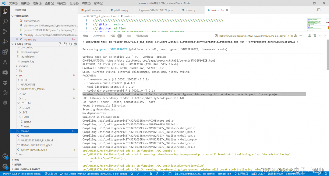
5. 更改完后,需要对 src 文件夹下的文件做替换,从 MM32F3270 官方的闪灯例程中找到对应文件替换过来,为了保险起见,将以上几个文件也包含到目录中(也是后面调试时才发现一定要添加进来的,不然编译通过但是无法正常运行,未包含启动文件),并且将 uart.c 的retarget 修改好适配 gcc 编译器
6. 至此已经完成了替代,可以进行 build 编译、upload 下载以及使用 Cortex-Debug 调试工程了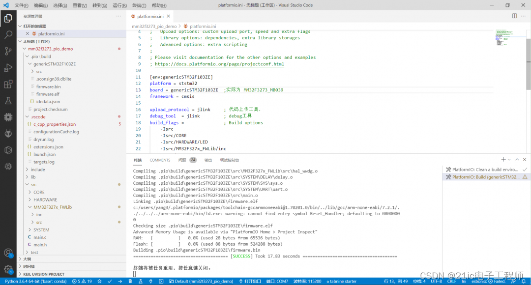
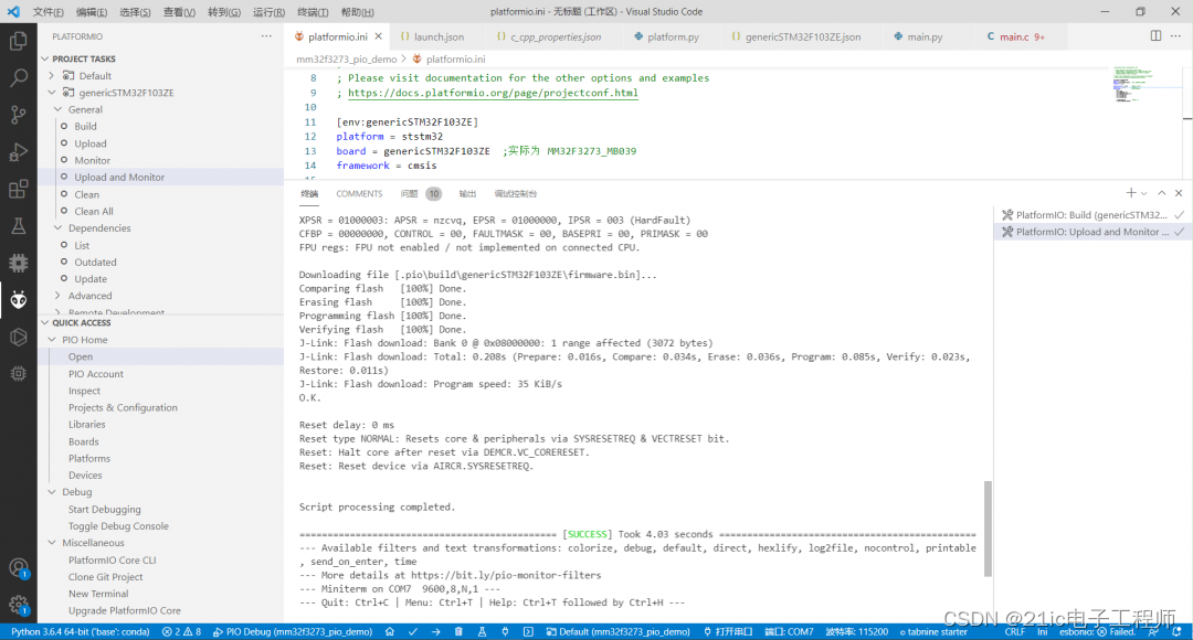
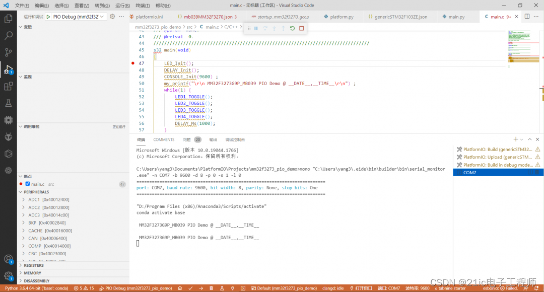
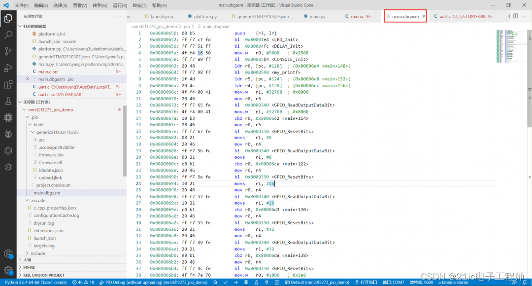
下载调试使用到 j-link 驱动包,由于该包也是通过依赖而新下载而来的,所以需要将灵动微的设备添加到驱动包中,这样才可以正常下载和调试。可以看到,调试环境很方便,还能看到反编译的汇编代码以及寄存器实时更新窗口,赞!![]()
三、后续待完成的集成要点
由于是从 ST 改写而来的集成,并未通过 PIO 官方 package 注册获得 MM32 本身的平台认证,所以后续是需要制作平台支持包以及板子支持包的,而且还得适配好 Arduino 、 SPL 、 mbed os 等几大主流框架,加上适配好 CMSIS DAP/openocd/ Serial 调试或者下载工具支持包。所以说,其实还有很多支持包需要官方做好,我们用户才能拿来就用,更加方便地进行 PIO 开发。
附件内容包含了我这次修改的支持包,以及调试运行的示例闪灯工程,大家可以拿去试着搭建起自己的环境,跑跑看了!
---------------------
作者:yang377156216
链接:https://bbs.21ic.com/icview-3235154-1-1.html
来源:21ic.com
此文章已获得原创/原创奖标签,著作权归21ic所有,任何人未经允许禁止转载。
最后
以上就是缓慢指甲油最近收集整理的关于[MM32生态]在 VS-Code 中还能怎么玩单片机?用 PlatformIO 试试的全部内容,更多相关[MM32生态]在内容请搜索靠谱客的其他文章。


![[MM32生态]在 VS-Code 中还能怎么玩单片机?用 PlatformIO 试试](https://www.shuijiaxian.com/files_image/reation/bcimg5.png)


发表评论 取消回复