师五喜,王栋伟,李宝全.多机器人领航-跟随型编队控制[J].天津工业大学学报,2018,37(02):72-78.
文章目录
- 1 机器人模型及问题描述
- 1.1 领航者运动学模型
- 1.2 跟随者运动学模型
- 2 控制器设计
- 3 仿真与实验
- 3.1 仿真
- Leader 状态
1 机器人模型及问题描述
1.1 领航者运动学模型
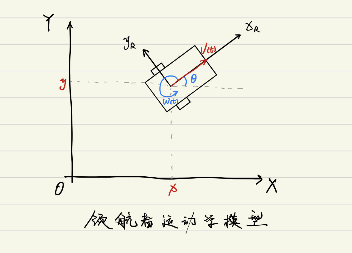
作者给出了如下动力学模型方程式:
[
x
˙
y
˙
z
˙
]
=
[
cos
θ
0
sin
θ
0
0
1
]
[
v
(
t
)
ω
(
t
)
]
(1)
left[begin{matrix} dot{x} \ dot{y} \ dot{z} \ end{matrix}right]= left[begin{matrix} cos theta & 0 \ sin theta & 0 \ 0 & 1 \ end{matrix}right] left[begin{matrix} v(t) \ omega(t) \ end{matrix}right] tag{1}
⎣⎡x˙y˙z˙⎦⎤=⎣⎡cosθsinθ0001⎦⎤[v(t)ω(t)](1)
展开方便理解
{
x
˙
=
cos
θ
⋅
v
(
t
)
y
˙
=
sin
θ
⋅
v
(
t
)
θ
˙
=
ω
(
t
)
left{begin{aligned} dot{x} &= cos theta cdot v(t) \ dot{y} &= sin theta cdot v(t) \ dot{theta} &= omega(t) \ end{aligned}right.
⎩⎪⎨⎪⎧x˙y˙θ˙=cosθ⋅v(t)=sinθ⋅v(t)=ω(t)
1.2 跟随者运动学模型
符号说明:
R
F
R_F
RF:跟随者机器人
L
F
L_F
LF:领航者机器人
v
L
v_L
vL:领航者机器人的线速度
ω
L
omega_L
ωL:领航者机器人的角速度
θ
L
theta_L
θL:领航者机器人的线速度与水平方向的夹角
v
F
v_F
vF:跟随者机器人的线速度
ω
F
omega_F
ωF:跟随者机器人的角速度
θ
F
theta_F
θF:跟随者机器人的线速度与水平方向的夹角
λ
L
−
F
lambda_{L-F}
λL−F:两机器人参考点之间的距离
φ
L
−
F
varphi_{L-F}
φL−F:领航者机器人前进方向与两机器人参考点连线的夹角
λ
L
−
F
d
lambda_{L-F}^d
λL−Fd:最终目标
φ
L
−
F
d
varphi_{L-F}^d
φL−Fd:最终目标
在世界坐标系中,虚拟机器人( V V V)与领航者( L L L)之间的位置关系为:
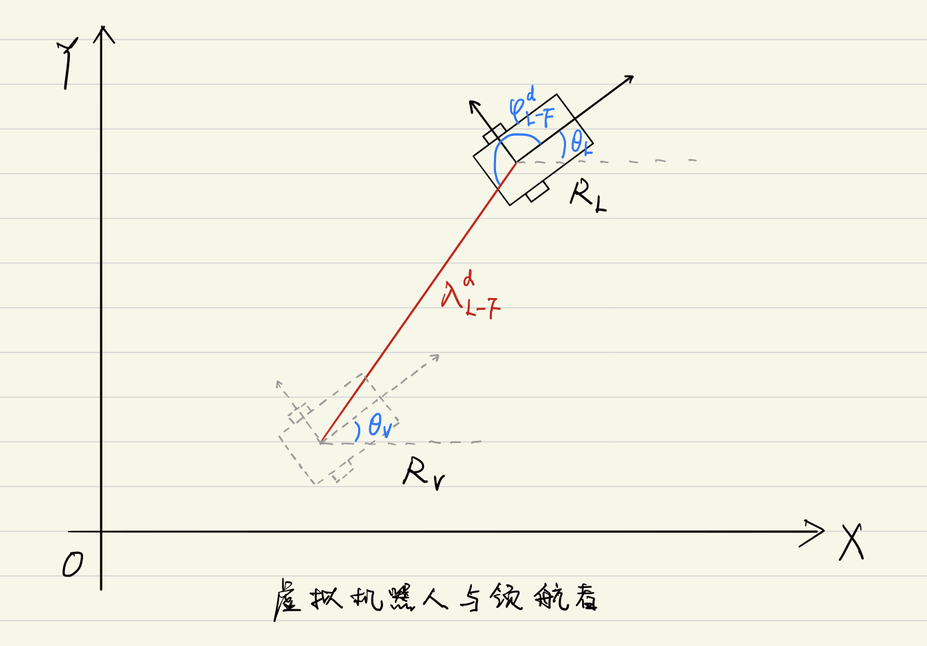
注意这里要明确一个事情,就是跟随者最终要达到的位置是虚拟机器人的位置,并不是达到领航机器人的位置,这一点要注意。
{ x V = x L + λ L − F d cos ( φ L − F d + θ L ) y V = y L + λ L − F d sin ( φ L − F d + θ L ) θ V = θ L (2) left{begin{aligned} x_V &= x_L + lambda_{L-F}^d ~cos(varphi_{L-F}^{d} + theta_L) \ y_V &= y_L + lambda_{L-F}^d ~sin(varphi_{L-F}^{d} + theta_L) \ theta_V &= theta_L \ end{aligned}right. tag{2} ⎩⎪⎨⎪⎧xVyVθV=xL+λL−Fd cos(φL−Fd+θL)=yL+λL−Fd sin(φL−Fd+θL)=θL(2)
跟随者(
F
F
F)与领航者(
L
L
L)之间的位置关系为:
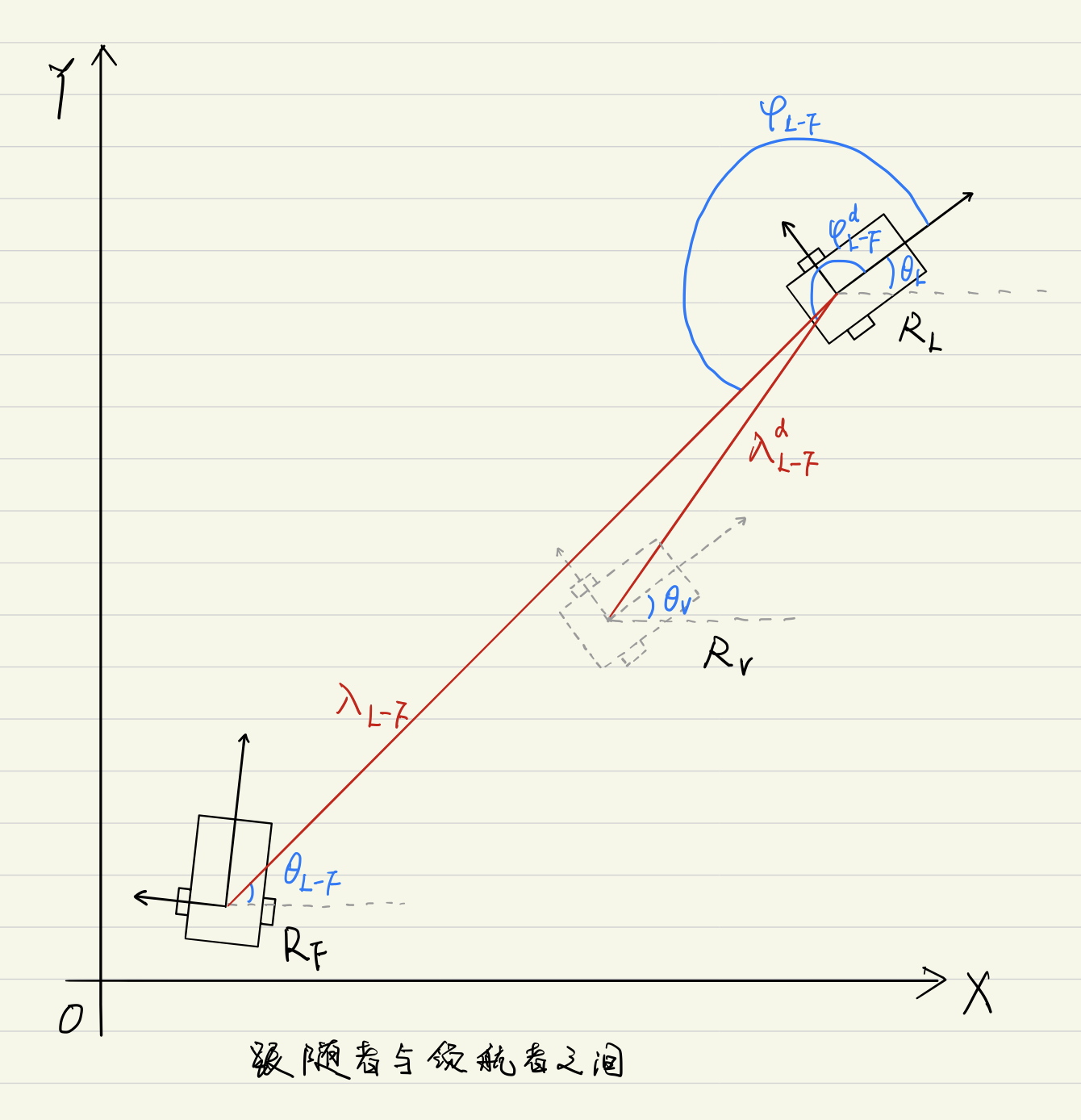
{ x F = x L + λ L − F cos ( φ L − F + θ L ) y F = y L + λ L − F sin ( φ L − F + θ L ) θ F = θ L − F (3) left{begin{aligned} x_F &= x_L + lambda_{L-F} ~cos(varphi_{L-F} + theta_L) \ y_F &= y_L + lambda_{L-F} ~sin(varphi_{L-F} + theta_L) \ theta_F &= theta_{L-F} \ end{aligned}right. tag{3} ⎩⎪⎨⎪⎧xFyFθF=xL+λL−F cos(φL−F+θL)=yL+λL−F sin(φL−F+θL)=θL−F(3)
虚拟机器人( V V V)与跟随者之间( F F F)的表达式为:
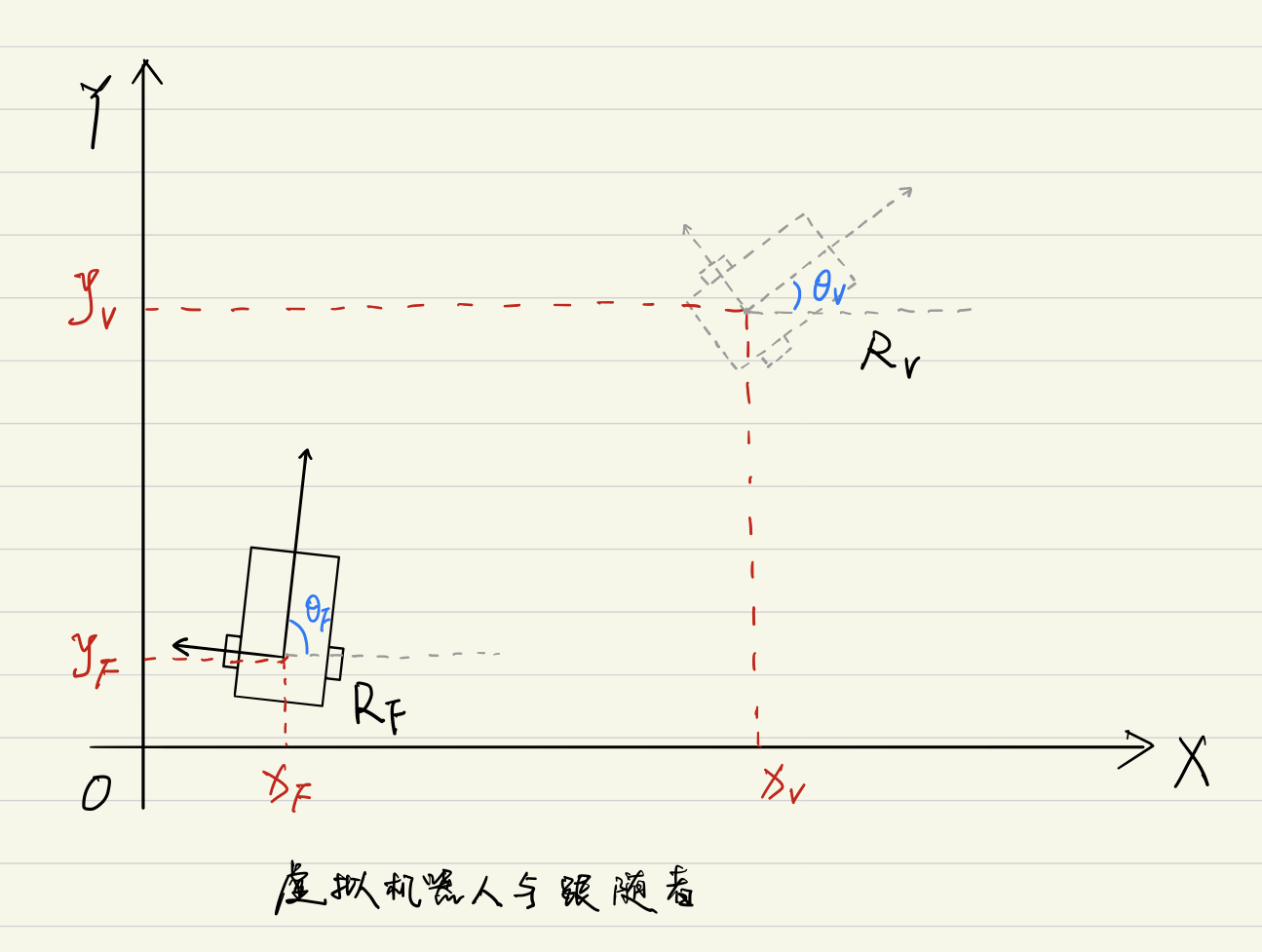
{ x e = x V − x F y e = y V − y F θ e = θ V − θ F (4) left{begin{aligned} x_e &= x_V - x_F \ y_e &= y_V - y_F \ theta_e &= theta_{V} - theta_{F} \ end{aligned}right. tag{4} ⎩⎪⎨⎪⎧xeyeθe=xV−xF=yV−yF=θV−θF(4)
通过转移矩阵,将其转换到跟随者机器人( F F F)自身的坐标系 x F − y F x_F - y_F xF−yF 下的误差表达式为:
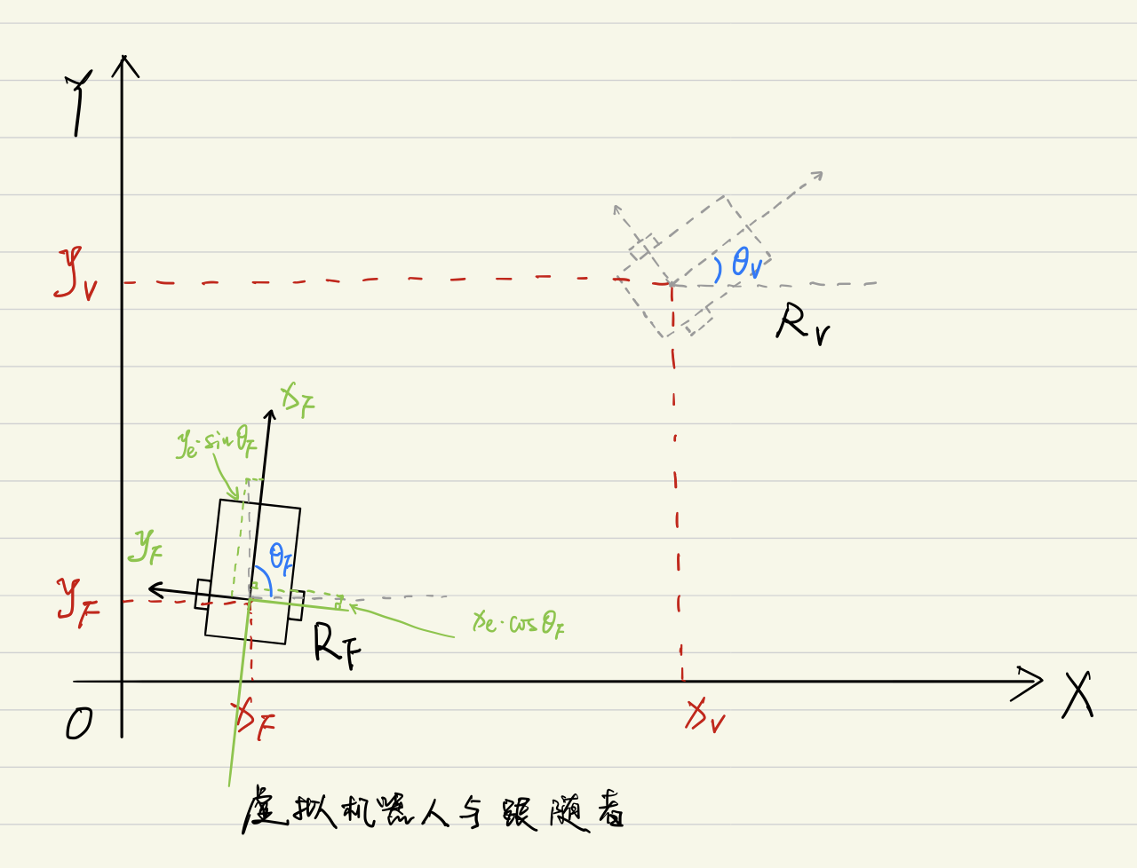
[ e x e y e θ ] = [ cos θ F sin θ F 0 − sin θ F cos θ F 0 0 0 1 ] [ x e y e θ e ] (5) left[begin{matrix} e_x \ e_y \ e_theta \ end{matrix}right]= left[begin{matrix} cos theta_F & sin theta_F & 0 \ -sin theta_F & cos theta_F & 0 \ 0 & 0 & 1 \ end{matrix}right] left[begin{matrix} x_e \ y_e \ theta_e \ end{matrix}right] tag{5} ⎣⎡exeyeθ⎦⎤=⎣⎡cosθF−sinθF0sinθFcosθF0001⎦⎤⎣⎡xeyeθe⎦⎤(5)
还是展开一下多一层理解:
{
e
x
=
cos
(
θ
F
)
x
e
+
sin
(
θ
F
)
y
e
e
y
=
−
sin
(
θ
F
)
x
e
+
cos
(
θ
F
)
y
e
e
θ
=
θ
e
left{begin{aligned} e_x &= cos (theta_F) x_e + sin(theta_F) y_e \ e_y &= -sin (theta_F) x_e + cos(theta_F) y_e \ e_theta &= theta_e \ end{aligned}right.
⎩⎪⎨⎪⎧exeyeθ=cos(θF)xe+sin(θF)ye=−sin(θF)xe+cos(θF)ye=θe
继续反推回去:
{
e
x
=
cos
(
θ
F
)
x
e
+
sin
(
θ
F
)
y
e
=
cos
(
θ
F
)
(
x
V
−
x
F
)
+
sin
(
θ
F
)
(
y
V
−
y
F
)
e
y
=
−
sin
(
θ
F
)
x
e
+
cos
(
θ
F
)
y
e
=
−
sin
(
θ
F
)
(
x
V
−
x
F
)
+
cos
(
θ
F
)
(
y
V
−
y
F
)
e
θ
=
θ
e
=
θ
V
−
θ
F
left{begin{aligned} e_x &= cos (theta_F) x_e + sin(theta_F) y_e \ &= cos (theta_F) (x_V - x_F) + sin(theta_F) (y_V - y_F) \ e_y &= -sin (theta_F) x_e + cos(theta_F) y_e \ &= -sin (theta_F) (x_V - x_F) + cos(theta_F) (y_V - y_F) \ e_theta &= theta_e \ &= theta_V - theta_F \ end{aligned}right.
⎩⎪⎪⎪⎪⎪⎪⎪⎪⎪⎨⎪⎪⎪⎪⎪⎪⎪⎪⎪⎧exeyeθ=cos(θF)xe+sin(θF)ye=cos(θF)(xV−xF)+sin(θF)(yV−yF)=−sin(θF)xe+cos(θF)ye=−sin(θF)(xV−xF)+cos(θF)(yV−yF)=θe=θV−θF
{ x F = x L + λ L − F cos ( φ L − F + θ L ) y F = y L + λ L − F sin ( φ L − F + θ L ) θ F = θ L − F (3) left{begin{aligned} x_F &= x_L + lambda_{L-F} ~cos(varphi_{L-F} + theta_L) \ y_F &= y_L + lambda_{L-F} ~sin(varphi_{L-F} + theta_L) \ theta_F &= theta_{L-F} \ end{aligned}right. tag{3} ⎩⎪⎨⎪⎧xFyFθF=xL+λL−F cos(φL−F+θL)=yL+λL−F sin(φL−F+θL)=θL−F(3)
{ x e = x V − x F y e = y V − y F θ e = θ V − θ F (4) left{begin{aligned} x_e &= x_V - x_F \ y_e &= y_V - y_F \ theta_e &= theta_{V} - theta_{F} \ end{aligned}right. tag{4} ⎩⎪⎨⎪⎧xeyeθe=xV−xF=yV−yF=θV−θF(4)
[ e x e y e θ ] = [ cos θ F sin θ F 0 − sin θ F cos θ F 0 0 0 1 ] [ x e y e θ e ] (5) left[begin{matrix} e_x \ e_y \ e_theta \ end{matrix}right]= left[begin{matrix} cos theta_F & sin theta_F & 0 \ -sin theta_F & cos theta_F & 0 \ 0 & 0 & 1 \ end{matrix}right] left[begin{matrix} x_e \ y_e \ theta_e \ end{matrix}right] tag{5} ⎣⎡exeyeθ⎦⎤=⎣⎡cosθF−sinθF0sinθFcosθF0001⎦⎤⎣⎡xeyeθe⎦⎤(5)
将式(3)(4)代入到(5)中得:(这里借用了式子(2))
e
x
=
cos
(
θ
F
)
(
x
V
−
x
F
)
+
sin
(
θ
F
)
(
y
V
−
y
F
)
=
cos
(
θ
F
)
(
x
V
−
x
L
−
λ
L
−
F
cos
(
φ
L
−
F
+
θ
L
)
)
+
sin
(
θ
F
)
(
y
V
−
y
L
−
λ
L
−
F
sin
(
φ
L
−
F
+
θ
L
)
)
=
cos
(
θ
F
)
(
x
L
+
λ
L
−
F
d
cos
(
φ
L
−
F
d
+
θ
L
)
−
x
L
−
λ
L
−
F
cos
(
φ
L
−
F
+
θ
L
)
)
+
sin
(
θ
F
)
(
y
L
+
λ
L
−
F
d
sin
(
φ
L
−
F
d
+
θ
L
)
−
y
L
−
λ
L
−
F
sin
(
φ
L
−
F
+
θ
L
)
)
=
cos
(
θ
F
)
(
λ
L
−
F
d
cos
(
φ
L
−
F
d
+
θ
L
)
−
λ
L
−
F
cos
(
φ
L
−
F
+
θ
L
)
)
+
sin
(
θ
F
)
(
λ
L
−
F
d
sin
(
φ
L
−
F
d
+
θ
L
)
−
λ
L
−
F
sin
(
φ
L
−
F
+
θ
L
)
)
=
λ
L
−
F
d
cos
(
φ
L
−
F
d
+
θ
L
)
cos
(
θ
F
)
−
λ
L
−
F
cos
(
φ
L
−
F
+
θ
L
)
cos
(
θ
F
)
+
λ
L
−
F
d
sin
(
φ
L
−
F
d
+
θ
L
)
sin
(
θ
F
)
−
λ
L
−
F
sin
(
φ
L
−
F
+
θ
L
)
sin
(
θ
F
)
=
λ
L
−
F
d
cos
(
φ
L
−
F
d
+
θ
L
)
cos
(
θ
F
)
+
λ
L
−
F
d
sin
(
φ
L
−
F
d
+
θ
L
)
sin
(
θ
F
)
−
λ
L
−
F
cos
(
φ
L
−
F
+
θ
L
)
cos
(
θ
F
)
−
λ
L
−
F
sin
(
φ
L
−
F
+
θ
L
)
sin
(
θ
F
)
=
λ
L
−
F
d
(
cos
(
φ
L
−
F
d
+
θ
L
)
cos
(
θ
F
)
+
sin
(
φ
L
−
F
d
+
θ
L
)
sin
(
θ
F
)
)
−
λ
L
−
F
(
cos
(
φ
L
−
F
+
θ
L
)
cos
(
θ
F
)
+
sin
(
φ
L
−
F
+
θ
L
)
sin
(
θ
F
)
)
begin{aligned} e_x =& cos (theta_F) (x_V - x_F) + sin(theta_F) (y_V - y_F) \ =& cos (theta_F) (x_V - x_L- lambda_{L-F} cos(varphi_{L-F} + theta_L)) \ &+ sin(theta_F) (y_V - y_L - lambda_{L-F} sin(varphi_{L-F} + theta_L)) \ =& cos (theta_F) (x_L + lambda_{L-F}^d ~cos(varphi_{L-F}^{d} + theta_L) - x_L- lambda_{L-F} cos(varphi_{L-F} + theta_L)) \ &+ sin(theta_F) (y_L + lambda_{L-F}^d ~sin(varphi_{L-F}^{d} + theta_L) - y_L - lambda_{L-F} sin(varphi_{L-F} + theta_L)) \ =& cos (theta_F) (lambda_{L-F}^d ~cos(varphi_{L-F}^{d} + theta_L) - lambda_{L-F} cos(varphi_{L-F} + theta_L)) \ &+ sin(theta_F) (lambda_{L-F}^d ~sin(varphi_{L-F}^{d} + theta_L) - lambda_{L-F} sin(varphi_{L-F} + theta_L)) \ =& lambda_{L-F}^d ~cos(varphi_{L-F}^{d} + theta_L) cos (theta_F) - lambda_{L-F} cos(varphi_{L-F} + theta_L) cos (theta_F) \ &+ lambda_{L-F}^d ~sin(varphi_{L-F}^{d} + theta_L) sin(theta_F) - lambda_{L-F} sin(varphi_{L-F} + theta_L) sin(theta_F) \ =& lambda_{L-F}^d ~cos(varphi_{L-F}^{d} + theta_L) cos (theta_F) + lambda_{L-F}^d ~sin(varphi_{L-F}^{d} + theta_L) sin(theta_F) \ &- lambda_{L-F} cos(varphi_{L-F} + theta_L) cos (theta_F)- lambda_{L-F} sin(varphi_{L-F} + theta_L) sin(theta_F) \ =& lambda_{L-F}^d ~(cos(varphi_{L-F}^{d} + theta_L) cos (theta_F) + ~sin(varphi_{L-F}^{d} + theta_L) sin(theta_F)) \ &- lambda_{L-F} ( cos(varphi_{L-F} + theta_L) cos (theta_F)+ sin(varphi_{L-F} + theta_L) sin(theta_F)) \ end{aligned}
ex=======cos(θF)(xV−xF)+sin(θF)(yV−yF)cos(θF)(xV−xL−λL−Fcos(φL−F+θL))+sin(θF)(yV−yL−λL−Fsin(φL−F+θL))cos(θF)(xL+λL−Fd cos(φL−Fd+θL)−xL−λL−Fcos(φL−F+θL))+sin(θF)(yL+λL−Fd sin(φL−Fd+θL)−yL−λL−Fsin(φL−F+θL))cos(θF)(λL−Fd cos(φL−Fd+θL)−λL−Fcos(φL−F+θL))+sin(θF)(λL−Fd sin(φL−Fd+θL)−λL−Fsin(φL−F+θL))λL−Fd cos(φL−Fd+θL)cos(θF)−λL−Fcos(φL−F+θL)cos(θF)+λL−Fd sin(φL−Fd+θL)sin(θF)−λL−Fsin(φL−F+θL)sin(θF)λL−Fd cos(φL−Fd+θL)cos(θF)+λL−Fd sin(φL−Fd+θL)sin(θF)−λL−Fcos(φL−F+θL)cos(θF)−λL−Fsin(φL−F+θL)sin(θF)λL−Fd (cos(φL−Fd+θL)cos(θF)+ sin(φL−Fd+θL)sin(θF))−λL−F(cos(φL−F+θL)cos(θF)+sin(φL−F+θL)sin(θF))
cos ( φ L − F + θ L − θ F ) = cos ( φ L − F + θ L ) cos ( θ F ) + sin ( φ L − F + θ L ) sin ( θ F ) cos(varphi_{L-F} + theta_L - theta_F) = cos(varphi_{L-F} + theta_L) cos(theta_F) + sin(varphi_{L-F} + theta_L) sin(theta_F) cos(φL−F+θL−θF)=cos(φL−F+θL)cos(θF)+sin(φL−F+θL)sin(θF)
[ e x e y e θ ] = [ λ L − F d cos ( φ L − F d + e θ ) − λ L − F cos ( φ L − F + e θ ) λ L − F d sin ( φ L − F d + e θ ) − λ L − F sin ( φ L − F + e θ ) θ L − θ F ] (6) left[begin{matrix} e_x \ e_y \ e_theta \ end{matrix}right]= left[begin{matrix} lambda_{L-F}^{d} cos(varphi_{L-F}^{d} + e_theta) - lambda_{L-F} cos(varphi_{L-F} + e_theta) \ lambda_{L-F}^{d} sin(varphi_{L-F}^{d} + e_theta) - lambda_{L-F} sin(varphi_{L-F} + e_theta) \ theta_L - theta_F \ end{matrix}right] tag{6} ⎣⎡exeyeθ⎦⎤=⎣⎡λL−Fdcos(φL−Fd+eθ)−λL−Fcos(φL−F+eθ)λL−Fdsin(φL−Fd+eθ)−λL−Fsin(φL−F+eθ)θL−θF⎦⎤(6)
求导得:
{ e ˙ x = v L cos e θ − v F + ω L λ L − F d sin ( φ L − F + e θ ) e ˙ y = v L sin e θ − ω F e x + ω L λ L − F d cos ( φ L − F + e θ ) e ˙ θ = ω L − ω F (7) left{begin{aligned} dot{e}_x &= v_L cos e_theta - v_F + omega_L lambda_{L-F}^{d} sin(varphi_{L-F} + e_theta) \ dot{e}_y &= v_L sin e_theta - omega_F e_x + omega_L lambda_{L-F}^{d} cos(varphi_{L-F} + e_theta) \ dot{e}_theta &= omega_L - omega_F \ end{aligned}right. tag{7} ⎩⎪⎨⎪⎧e˙xe˙ye˙θ=vLcoseθ−vF+ωLλL−Fdsin(φL−F+eθ)=vLsineθ−ωFex+ωLλL−Fdcos(φL−F+eθ)=ωL−ωF(7)
注意,式(7)中第三个角度误差的式子,也可以为 e θ = θ L − θ F e_theta = theta_L - theta_F eθ=θL−θF。
至此,机器人编队控制问题转化为跟随机器人 R F R_F RF 对虚拟机器人 R V R_V RV 的轨迹跟踪问题,即寻找合适的控制律( v F , ω F v_F, omega_F vF,ωF)使得式(7)描述的闭环系统渐近稳定.
2 控制器设计
设计控制器如下:
v
F
=
v
L
cos
e
θ
+
γ
v
F
+
ϕ
1
(9)
v_F = v_L cos e_{theta} + gamma_{vF} + phi_1 tag{9}
vF=vLcoseθ+γvF+ϕ1(9)
ω F = ω L + k v L e y 1 + e x 2 + e y 2 + γ ω F + ϕ 2 (10) omega_F = omega_L + frac{k v_L e_y}{sqrt{1 + e^2_x + e^2_y}} + gamma_{omega F} + phi_2 tag{10} ωF=ωL+1+ex2+ey2kvLey+γωF+ϕ2(10)
3 仿真与实验
3.1 仿真
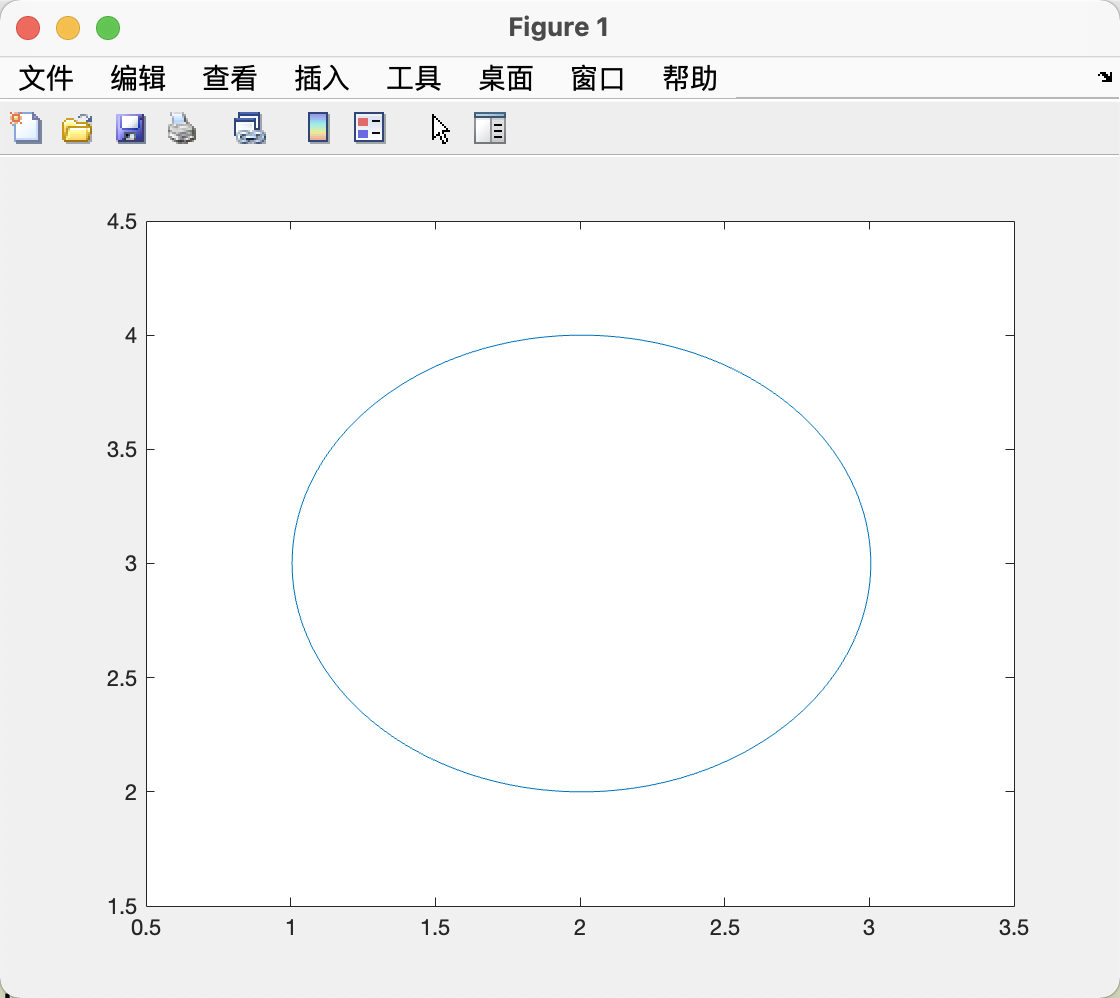
Leader 状态
% Paper: 2018_多机器人领航-跟随型编队控制
% Author: Z-JC
% Data: 2021-11-20
clear
clc


%%
% Leader1's states
xL(1,1)     = 2;
yL(1,1)     = 2;
thetaL(1,1) = 0;
vL = 0.1;
wL = 0.1;

% Parameters
alpha1 = 0.45;
alpha2 = 0.5;
k = 3.0;

% Time states
t(1,1) = 0;
dT = 0.1;

for i=1:999
    % Record Time
    t(1,i+1) = t(1,i) + dT;

    % Updta Leader
    thetaL(1,i+1) = thetaL(1,i) + dT * wL;
    xL(1,i+1) = xL(1,i) + dT * vL * cos(thetaL(1,i));
    yL(1,i+1) = yL(1,i) + dT * vL * sin(thetaL(1,i));

end


%%
plot(xL,yL);
xlim([0.5,3.5]); ylim([1.5,4.5]);
最后
以上就是尊敬机器猫最近收集整理的关于【Paper】2018_多机器人领航-跟随型编队控制1 机器人模型及问题描述2 控制器设计3 仿真与实验的全部内容,更多相关【Paper】2018_多机器人领航-跟随型编队控制1内容请搜索靠谱客的其他文章。


发表评论 取消回复