- 创建自己的URDF文件
1.1创建树形结构文件
在这部分教程中要创建的将是下面的图形所描述的机器人的urdf文件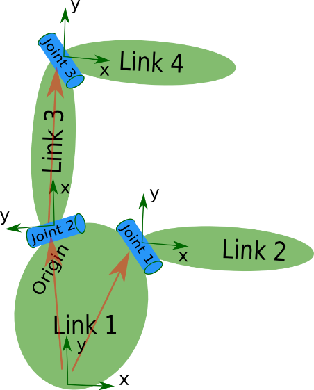
图片中这个机器人是一个树形结构的。让我们开始非常简单的创建这个树型结构的描述文件,不用担心维度等的问题。创建一个my_robot.urdf文件,内容如下:
<robot name="test_robot">
<link name="link1" />
<link name="link2" />
<link name="link3" />
<link name="link4" />
<joint name="joint1" type="continuous">
<parent link="link1"/>
<child link="link2"/>
</joint>
<joint name="joint2" type="continuous">
<parent link="link1"/>
<child link="link3"/>
</joint>
<joint name="joint3" type="continuous">
<parent link="link3"/>
<child link="link4"/>
</joint>
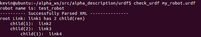
</robot>所以,这里是仅仅创建了一个非常简单的结构。现在我们来看一看我们能否解读这个文件。可以使用一些简单的命令行工具,来检查你的语法是否正确。
需要安装urdfdom作为一个上游的ROS独立包
sudo apt-get install liburdfdom-tools现在运行检查命令(基于indigo)
check_urdf my_robot.urdf如果一切顺利的话,将会看到的是
1.2添加坐标系(维度)信息
现在有了一个基本的树形结构,让我们来添加合适的坐标系信息。如你在图片中看到的,每一个连接的参考系都在连接的底部,而且关节的参考系是完全相同的。所以,要添加维度到我们的树上,我们要确认的就是从一个连接到自己子连接的关机的偏移量。为了完成这一部分,我们将会为每一个关节添加.
比如,我们来看第二个关节。joint2是link1在Y方向上的偏移,在X轴负方向上有一点点偏移,而且绕Z轴旋转了90度,所以我们需要添加下面的元素。
<origin xyz=”-2 5 0” rpy=”0 0 1.57” />在每一个关节重复这一改变,这个urdf文件看起来就是这样子的:
<robot name="test_robot">
  <link name="link1" />
  <link name="link2" />
  <link name="link3" />
  <link name="link4" />


  <joint name="joint1" type="continuous">
    <parent link="link1"/>
    <child link="link2"/>
    <origin xyz="5 3 0" rpy="0 0 0" />
  </joint>

  <joint name="joint2" type="continuous">
    <parent link="link1"/>
    <child link="link3"/>
    <origin xyz="-2 5 0" rpy="0 0 1.57" />
  </joint>

  <joint name="joint3" type="continuous">
    <parent link="link3"/>
    <child link="link4"/>
    <origin xyz="5 0 0" rpy="0 0 -1.57" />
  </joint>
</robot>
更新你的my_robot.urd文件,并通过解析器运行它。
check_urdf my_robot.urdf1.3 完成运动学部分
我们现在还不确定的部分就是关节绕着哪个轴旋转。一旦我们添加了这个部分,我们实际上有了这个机器人完整的运动学模型。我们要做的就是添加元素到每一个joint中。axis确定在局部的旋转轴。
所以,如果你看joint2,你会看到它是绕着Y轴正方向旋转。所以,需要简单添加下面的内容到关节元素中:
<axis xyz=”0 1 0” />相似的,需要向joint1中添加下面的内容:
<axis xyz=”-0.707 0.707 0” />如果向所有关节中添加了这一元素的话,这个urdf文件看起来就是下面这样的:
<robot name="test_robot">
  <link name="link1" />
  <link name="link2" />
  <link name="link3" />
  <link name="link4" />

  <joint name="joint1" type="continuous">
    <parent link="link1"/>
    <child link="link2"/>
    <origin xyz="5 3 0" rpy="0 0 0" />
    <axis xyz="-0.9 0.15 0" />
  </joint>

  <joint name="joint2" type="continuous">
    <parent link="link1"/>
    <child link="link3"/>
    <origin xyz="-2 5 0" rpy="0 0 1.57" />
    <axis xyz="-0.707 0.707 0" />
  </joint>

  <joint name="joint3" type="continuous">
    <parent link="link3"/>
    <child link="link4"/>
    <origin xyz="5 0 0" rpy="0 0 -1.57" />
    <axis xyz="0.707 -0.707 0" />
  </joint>
</robot>
更新你的my_robot.urdf文件,并用解析器运行它
check_urdf my_robot.urdf到这里为止,你就创建了你的第一个URDF机器人描述。现在你可以尝试用graphiz将你的URDF可视化。
urdf_to_graphiz my_robot.urdf打开产生的文件,比如用evince test_robot.pdf
- 解析一个URDF文件
2.1解析一个URDF文件
首先,我们创建一个依赖于urdf解析器的包。
  $ cd ~/catkin_ws/src
  $ catkin_create_pkg testbot_description urdf
  $ cd testbot_description
现在我们来创建一个urdf文件夹来存储我们刚刚创建的urdf文件。
mkdir urdf按照一般的惯例,urdf文件是在一个名为MYROBOT_description的包中,它的标准的子文件夹还包括有/meshes, /media 和/cd,就像是下面这样:
/MYROBOT_description
  package.xml
  CMakeLists.txt
  /urdf
  /meshes
  /materials
  /cad
接下来,将我们创建的my_robot.urdf拷贝到我们刚刚创建的文件夹中。
$ cp /path/to/.../testbot_description/urdf/my_robot.urdf创建一个src文件夹,并创建src/parser.cpp文件
#include <urdf/model.h>
#include "ros/ros.h"

int main(int argc, char** argv){
  ros::init(argc, argv, "my_parser");
  if (argc != 2){
    ROS_ERROR("Need a urdf file as argument");
    return -1;
  }
  std::string urdf_file = argv[1];

  urdf::Model model;
  if (!model.initFile(urdf_file)){
    ROS_ERROR("Failed to parse urdf file");
    return -1;
  }
  ROS_INFO("Successfully parsed urdf file");
  return 0;
}
真正的动作是发生在 urdf::Model model;这两行。如果URDF文件能够成功解析的话initFile方法返回true。
if (!model.initFile(urdf_file)){
然后我们来尝试运行这个程序,首先向CmakeList.txt文件中添加这两行
add_executable(parser src/parser.cpp)
target_link_libraries(parser ${catkin_LIBRARIES})
构建你的包,并运行它
  $ catkin_make
  $ .<path>/parser <path>my_robot.urdf
  # ./devel/lib/robot_description/parser /src/robot_description/urdf/my_robot.urdf (for example)
输出应该看起来是这样的:
[ INFO] 1254520129.560927000: Successfully parsed urdf file现在,可以看一下code API(http://docs.ros.org/api/urdf/html/)来看看如何使用你刚刚创建的URDF模型。一个很好的URDF模型类的例子在
https://github.com/ros-visualization/rviz/blob/groovy-devel/src/rviz/robot/robot.cpp
- 在自己的机器人上使用robot state publisher
这部分教程将解释如何使用机器人状态发布者来发布机器人状态到tf。
当你的机器人是有很多关联坐标系的机器人时,把它们全部发布到tf也是一项相当可观的任务。robot state publisher是一个可以帮助你处理这项任务的工具。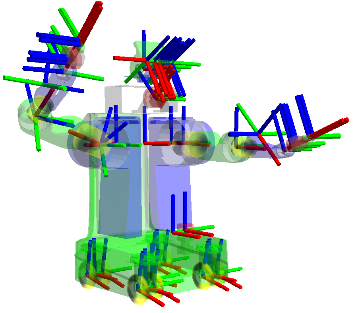
robot state publisher帮助你把你的机器人状态发布到tf转换库中。robot state publisher内部有一个机器人的运动学模型,所以给定机器人位置,robot state publisher能够计算和发布机器人每一个link的3D位姿。
你可以用robot state publisher作为一个单独的节点或者一个库。
3.1 作为一个单独的ROS节点运行
3.1.1 robot_state_publisher
运行机器人状态发布者最简单的方式就是作为一个节点运行。对于一般使用者来说,我们推荐这样使用。你需要两样东西来运行机器人状态发布者:
- 一个从Parameter Server下载的urdf xml机器人描述。
- 一个将关节位置用sensor_msgs/JointState格式发布的源。
如何为robot_state_publisher配置参数和主题,请阅读下面的部分。
3.1.1.1 订阅的主题:
joint_states(sensor_msgs/JointState)
关节位置信息
3.1.1.2 参数
robot_description(urdf map)
urdf xml机器人描述。这可以通过urdf_model::initParam来完成。
tf_prefix(string)
为命名空间发布变化设置tf前缀。
publish_frequency(double)
状态发布者的发布频率,默认50赫兹。
3.1.2 例子launch文件
一旦已经设置了XML机器人描述文件和一个关节位置信息源文件,简单创建一个launch文件如下:
  <launch>
    <node pkg="robot_state_publisher" type="robot_state_publisher" name="rob_st_pub" >
      <remap from="robot_description" to="different_robot_description" />
      <remap from="joint_states" to="different_joint_states" />
    </node>
  </launch>
3.2 作为一个库运行
高级用户也可以将机器人状态发布者在他们自己的C++代码中作为一个库来使用。在你包含了头文件之后:
#include <robot_state_publisher/robot_state_publisher.h>你需要的就是一个采用了KDL树的构造函数:
RobotStatePublisher(const KDL::Tree& tree);现在,每次你想要发布你的机器人状态,你调用publishTransform函数即可:
//publish moving joints
void publishTransforms(const std::map<std::string, double>& joint_positions, const ros::Time& time):
//publish fixed joints
void publishFixedTransforms();
第一个变量是一个关节名称和关节位置的map,第二个参数是关节位置记录的时间。如果这个map不包括所有的关节名称也是没有问题的。如果这个map包含了一些关节名称,而这些关节名称不是运动模型的一部分,也是没有问题的。要是注意,如果你不告诉关节状态发布者你运动模型的一些关节,你的tf树将不能完成。
4.开始使用KDL解析器
4.1 构建KDL解析器
rosdep install kdl_parser这条命令将会安装kdl_parser所有的外部依赖包。构建包,运行:
rosmake kdl_parser4.2 使用你的代码
首先,添加KDL解析器作为一个依赖包,到你的package.xml文件中
<package>
    ...
    <depend package="kdl_parser" />
    ...
  </package>
在你的C++代码开始阶段,添加KDL解析器,包括下面的文件
#include <kdl_parser/kdl_parser.hpp>现在,有不同的方法来继续进行,你可以从一个urdf用多种方法构建一个KDL树。
4.2.1从一个文件
 KDL::Tree my_tree;
   if (!kdl_parser::treeFromFile("filename", my_tree)){
      ROS_ERROR("Failed to construct kdl tree");
      return false;
   }
创建PR2的urdf文件,运行下面的命令
rosrun xacro xacro.py `rospack find pr2_description`/robots/pr2.urdf.xacro > pr2.urdf4.2.2 从一个参数服务器
 KDL::Tree my_tree;
   ros::NodeHandle node;
   std::string robot_desc_string;
   node.param("robot_description", robot_desc_string, string());
   if (!kdl_parser::treeFromString(robot_desc_string, my_tree)){
      ROS_ERROR("Failed to construct kdl tree");
      return false;
   }
4.2.3 从一个xml元素
KDL::Tree my_tree;
   TiXmlDocument xml_doc;
   xml_doc.Parse(xml_string.c_str());
   xml_root = xml_doc.FirstChildElement("robot");
   if (!xml_root){
      ROS_ERROR("Failed to get robot from xml document");
      return false;
   }
   if (!kdl_parser::treeFromXml(xml_root, my_tree)){
      ROS_ERROR("Failed to construct kdl tree");
      return false;
   }
4.2.4 从一个URDF模型
 KDL::Tree my_tree;
   urdf::Model my_model;
   if (!my_model.initXml(....)){
      ROS_ERROR("Failed to parse urdf robot model");
      return false;
   }
   if (!kdl_parser::treeFromUrdfModel(my_model, my_tree)){
      ROS_ERROR("Failed to construct kdl tree");
      return false;
   }
关于更多地细节,可以参考API文档:
http://docs.ros.org/api/kdl_parser/html/namespacekdl__parser.html
5.用robot_state_publisher使用URDF
这部分教程完整的机器人URDF模型使用robot_state_publisher的例子。首先,我们创建所有URDF模型的需要的部分。然后我们写一个节点来发布关键状态和转换信息。最后,我们运行所有的部分。
5.1 创建URDF文件
这里有一个7自由度的接近R2-D2的模型。
<robot name="r2d2">

<link name="axis">
  <inertial>
    <mass value="1"/>
    <inertia ixx="100" ixy="0" ixz="0" iyy="100" iyz="0" izz="100" />
    <origin/>
  </inertial>
  <visual>
    <origin xyz="0 0 0" rpy="1.57 0 0" />
    <geometry>
      <cylinder radius="0.01" length=".5" />
    </geometry>
    <material name="gray">
      <color rgba=".2 .2 .2 1" />
    </material>
  </visual>

  <collision>
    <origin xyz="0 0 0" rpy="1.57 0 0" />
    <geometry>
      <cylinder radius="0.01" length=".5" />
    </geometry>
    <contact_coefficients mu="0" kp="1000.0" kd="1.0"/>
  </collision>
</link>

<link name="leg1">
  <inertial>
    <mass value="1"/>
    <inertia ixx="100" ixy="0" ixz="0" iyy="100" iyz="0" izz="100" />
    <origin/>
  </inertial>

  <visual>
    <origin xyz="0 0 -.3" />
    <geometry>
      <box size=".20 .10 .8" />
    </geometry>
    <material name="white">
      <color rgba="1 1 1 1"/>
    </material>
  </visual>

  <collision>
    <origin xyz="0 0 -.3" />
    <geometry>
      <box size=".20 .10 .8" />
    </geometry>
    <contact_coefficients mu="0" kp="1000.0" kd="1.0"/>
  </collision>
</link>

<joint name="leg1connect" type="fixed">
  <origin xyz="0 .30 0" />
  <parent link="axis"/>
  <child link="leg1"/>
</joint>

<link name="leg2">
  <inertial>
    <mass value="1"/>
    <inertia ixx="100" ixy="0" ixz="0" iyy="100" iyz="0" izz="100" />
    <origin/>
  </inertial>

  <visual>
    <origin xyz="0 0 -.3" />
    <geometry>
      <box size=".20 .10 .8" />
    </geometry>
    <material name="white">
      <color rgba="1 1 1 1"/>
    </material>
  </visual>

  <collision>
    <origin xyz="0 0 -.3" />
    <geometry>
      <box size=".20 .10 .8" />
    </geometry>
    <contact_coefficients mu="0" kp="1000.0" kd="1.0"/>
  </collision>
</link>

<joint name="leg2connect" type="fixed">
  <origin xyz="0 -.30 0" />
  <parent link="axis"/>
  <child link="leg2"/>
</joint>

<link name="body">
  <inertial>
    <mass value="1"/>
    <inertia ixx="100" ixy="0" ixz="0" iyy="100" iyz="0" izz="100" />
    <origin/>
  </inertial>

  <visual>
    <origin xyz="0 0 -0.2" />
    <geometry>
      <cylinder radius=".20" length=".6"/>
    </geometry>
    <material name="white"/>
  </visual>

  <collision>
    <origin xyz="0 0 0.2" />
    <geometry>
      <cylinder radius=".20" length=".6"/>
    </geometry>
    <contact_coefficients mu="0" kp="1000.0" kd="1.0"/>
  </collision>
</link>

<joint name="tilt" type="revolute">
  <parent link="axis"/>
  <child link="body"/>
  <origin xyz="0 0 0" rpy="0 0 0" />
  <axis xyz="0 1 0" />
  <limit upper="0" lower="-.5" effort="10" velocity="10" />
</joint>

<link name="head">
  <inertial>
    <mass value="1"/>
    <inertia ixx="100" ixy="0" ixz="0" iyy="100" iyz="0" izz="100" />
    <origin/>
  </inertial>

  <visual>
    <geometry>
      <sphere radius=".4" />
    </geometry>
    <material name="white" />
  </visual>

  <collision>
    <origin/>
    <geometry>
      <sphere radius=".4" />
    </geometry>
    <contact_coefficients mu="0" kp="1000.0" kd="1.0"/>
  </collision>
</link>

<joint name="swivel" type="continuous">
  <origin xyz="0 0 0.1" />
  <axis xyz="0 0 1" />
  <parent link="body"/>
  <child link="head"/>
</joint>

<link name="rod">
  <inertial>
    <mass value="1"/>
    <inertia ixx="100" ixy="0" ixz="0" iyy="100" iyz="0" izz="100" />
    <origin/>
  </inertial>

  <visual>
    <origin xyz="0 0 -.1" />
    <geometry>
      <cylinder radius=".02" length=".2" />
    </geometry>
    <material name="gray" />

  </visual>

  <collision>
    <origin/>
    <geometry>
      <cylinder radius=".02" length=".2" />
    </geometry>
    <contact_coefficients mu="0" kp="1000.0" kd="1.0"/>
  </collision>
</link>

<joint name="periscope" type="prismatic">
  <origin xyz=".12 0 .15" />
  <axis xyz="0 0 1" />
  <limit upper="0" lower="-.5" effort="10" velocity="10" />
  <parent link="head"/>
  <child link="rod"/>
</joint>

<link name="box">
  <inertial>
    <mass value="1"/>
    <inertia ixx="100" ixy="0" ixz="0" iyy="100" iyz="0" izz="100" />
    <origin/>
  </inertial>

  <visual>
    <geometry>
      <box size=".05 .05 .05" />
    </geometry>
    <material name="blue" >
      <color rgba="0 0 1 1" />
    </material>
  </visual>

  <collision>
    <origin/>
    <geometry>
      <box size=".05 .05 .05" />
    </geometry>
    <contact_coefficients mu="0" kp="1000.0" kd="1.0"/>
  </collision>
</link>
<joint name="boxconnect" type="fixed">
  <origin xyz="0 0 0" />
  <parent link="rod"/>
  <child link="box"/>
</joint>

</robot>
5.2 发布状态
现在我们需要一个方法来确定机器人是在哪个状态下。为了完成这个目标,我们必须确定所有三个关节和全部的里程。从创建一个包开始:
cd %TOP_DIR_YOUR_CATKIN_WS%/src
catkin_create_pkg r2d2 roscpp rospy tf sensor_msgs std_msgs
然后打开编辑器,添加下面的内容到src/state_publisher.cpp文件中:
#include <string>
#include <ros/ros.h>
#include <sensor_msgs/JointState.h>
#include <tf/transform_broadcaster.h>

int main(int argc, char** argv) {
    ros::init(argc, argv, "state_publisher");
    ros::NodeHandle n;
    ros::Publisher joint_pub = n.advertise<sensor_msgs::JointState>("joint_states", 1);
    tf::TransformBroadcaster broadcaster;
    ros::Rate loop_rate(30);

    const double degree = M_PI/180;

    // robot state
    double tilt = 0, tinc = degree, swivel=0, angle=0, height=0, hinc=0.005;

    // message declarations
    geometry_msgs::TransformStamped odom_trans;
    sensor_msgs::JointState joint_state;
    odom_trans.header.frame_id = "odom";
    odom_trans.child_frame_id = "axis";

    while (ros::ok()) {
        //update joint_state
        joint_state.header.stamp = ros::Time::now();
        joint_state.name.resize(3);
        joint_state.position.resize(3);
        joint_state.name[0] ="swivel";
        joint_state.position[0] = swivel;
        joint_state.name[1] ="tilt";
        joint_state.position[1] = tilt;
        joint_state.name[2] ="periscope";
        joint_state.position[2] = height;


        // update transform
        // (moving in a circle with radius=2)
        odom_trans.header.stamp = ros::Time::now();
        odom_trans.transform.translation.x = cos(angle)*2;
        odom_trans.transform.translation.y = sin(angle)*2;
        odom_trans.transform.translation.z = .7;
        odom_trans.transform.rotation = tf::createQuaternionMsgFromYaw(angle+M_PI/2);

        //send the joint state and transform
        joint_pub.publish(joint_state);
        broadcaster.sendTransform(odom_trans);

        // Create new robot state
        tilt += tinc;
        if (tilt<-.5 || tilt>0) tinc *= -1;
        height += hinc;
        if (height>.2 || height<0) hinc *= -1;
        swivel += degree;
        angle += degree/4;

        // This will adjust as needed per iteration
        loop_rate.sleep();
    }
    return 0;
}
5.3 Launch文件
这个launch文件假设你正在使用的包名称为“r2d2”节点名称为“state_publisher”,你已经保存了上面的urdf文件到r2d2包中
<launch>
        <param name="robot_description" command="cat $(find r2d2)/model.xml" />
        <node name="robot_state_publisher" pkg="robot_state_publisher" type="state_p-ublisher" />
        <node name="state_publisher" pkg="r2d2" type="state_publisher" />
</launch>
5.4 查看结果
首先我们应该编辑一下我们上面的代码所在的Cmake.txt文件。确认添加tf依赖。
find_package(catkin REQUIRED COMPONENTS roscpp rospy std_msgs tf)注意roscpp是用来解析我们编写和产生的state_publisher节点的代码。也需要添加下面的内容到Cmakelists.txt文件的末尾以用来产生state_publisher节点:
include_directories(include ${catkin_INCLUDE_DIRS})
add_executable(state_publisher src/state_publisher.cpp)
target_link_libraries(state_publisher ${catkin_LIBRARIES})
现在运行这个包 现在,我们应该到工作空间文件夹下构建包:
catkin_makeroslaunch r2d2 display.launch在一个新的终端中运行rviz:
rosrun rviz rviz选择odom作为你的固定坐标系。然后选择”Add Display“并添加一个机器人模型显示和一个TF显示。
最后
以上就是忧伤曲奇最近收集整理的关于由浅到深理解ROS URDF教程的全部内容,更多相关由浅到深理解ROS内容请搜索靠谱客的其他文章。


发表评论 取消回复