一.camera名词解释
在现代移动设备中,常用一种接口用来连接SOC和LCD和Camera,这种接口就是MIPI
其中SOC和LCD连接叫 DSI(DisplayCommandSet),SOC和Camera连接叫CSI(DisplaySerialInterface)。
二.camera数据通路

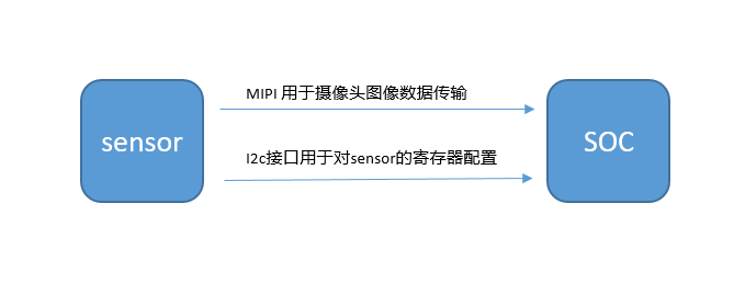
一般情况下,Camera和SOC有两个接口进行连接,分为为MIPI接口和I2C接口,其中MIPI接口用来传输图像的数据,数据传输路径为从Sensor传输到SOC。另一个接口为I2C接口,主要是用来SOC对Sensor初始化配置寄存器和摄像头参数的配置,比如要进行图像数据捕获的时候就需要通过i2c对Sensor的寄存器进行配置。


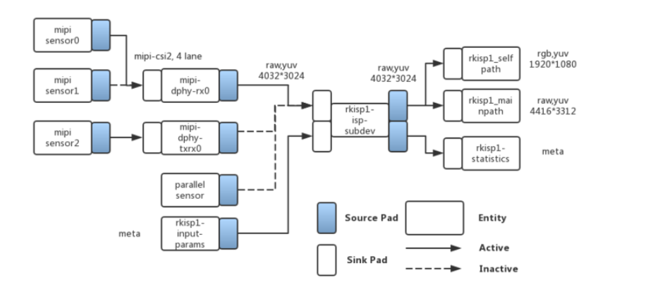
由上面的两个图可以看到,光线经过Sensor之后,Sensor芯片经过ADC转换生成图像数据,然后Sensor生成的图像数据经过MIPI总线进入SOC,进入SOC之后经过ISP进行图像处理。所以由此可以可以看出,Camera驱动V4L2一定有这3部分组成,第一部分与Sensor相关的,比如控制Sensor的寄存器进行配置,这一部分是有Sensor厂家提供。第二部分和MIPI相关的,需要MIPI进行图像传输,所以驱动应该就有这一部分的驱动,这部分一般是由SOC厂家提供。第三部分就是ISP部分,有些SOC有ISP图像处理模块,经过MIPI传输的图像进入SOC之后需要在传入SOC的ISP模块对图像进一步进行加工,所以一定是有一部分驱动是描述ISP模块的。
三.Camera 使用
用单目摄像头配置为full mode,若使用双目摄像头配置为split mode。
full mode:
- 仅使用csi2_dphy0,csi2_dphy0与csi2_dphy1/csi2_dphy2互斥,不可同时使用;
- data lane最大4 lanes;
- 最大速率2.5Gbps/lane;
split mode:
-
仅使用csi2_dphy1和csi2_dphy2, 与csi2_dphy0互斥,不可同时使用;
-
csi2_dphy1和csi2_dphy2可同时使用;
-
csi2_dphy1和csi2_dphy2各自的data lane最大是2 lanes;
-
csi2_dphy1对应物理dphy的lane0/lane1;
-
csi2_dphy2对应物理dphy的lane2/lane3;
-
最大速率2.5Gbps/lane
四.点亮sensergc2053/gc2093
添加驱动源文件:
kerneldriversmediai2cgc2053.c

kerneldriversmediai2cgc2093.c

kernelincludeconfigvideogc2053.h

kernelincludeconfigvideogc2093.h
修改Makefile:
kernel/drivers/media/i2c/Makefile

+obj-$(CONFIG_VIDEO_GC2053)	+= gc2053.o
+obj-$(CONFIG_VIDEO_GC2093)	+= gc2093.o
修改Kconfig:
config VIDEO_GC2053
	tristate "GalaxyCore GC2053 sensor support"
	depends on I2C && VIDEO_V4L2 && VIDEO_V4L2_SUBDEV_API
	depends on MEDIA_CAMERA_SUPPORT
	select V4L2_FWNODE
	help
	  Support for the GalaxyCore GC2053 sensor.

	  To compile this driver as a module, choose M here: the
	  module will be called gc2053.

config VIDEO_GC2093
	tristate "GalaxyCore GC2093 sensor support"
	depends on I2C && VIDEO_V4L2 && VIDEO_V4L2_SUBDEV_API
	depends on MEDIA_CAMERA_SUPPORT
	select V4L2_FWNODE
	help
	  Support for the GalaxyCore GC2093 sensor.

	  To compile this driver as a module, choose M here: the
	  module will be called gc2093.
添加驱动对应的宏开关:
kernel/arch/arm64/configs/rockchip_linux_defconfig
CONFIG_VIDEO_GC2053=y
CONFIG_VIDEO_GC2093=y
添加完以上三个,就是在内核中添加驱动完成,可以看开机log中有没有驱动中的log来看驱动有没有被加载,没加载可能存在多个宏开关xxxx_defconfig,需要重新添加。
添加设备树:
首先找到编译进内核的这板dts
/device/rockchip/rk356x/BoardConfig-rk3566-evb2-lp4x-v10.mk
# Kernel dts
export RK_KERNEL_DTS=rk3566-evb2-lp4x-v10-linux
找到rk3566-evb2-lp4x-v10-linux
添加双摄dtsi头文件:
#include "rk3566-tamsong-cam-2ms2m.dtsi"&i2c4 {
status = "okay";
gc2053: gc2053@37 { //IR
status = "okay";
compatible = "galaxycore,gc2053";//需要与驱动中的匹配字符串一致
reg = <0x37>;// sensor I2C 设备地址,7位
//查看硬件配置引脚,特别注意clocks与pinctrl-0一一对应,
//CLK_CAM0_OUT->cam_clkout0, CLK_CAM1_OUT->cam_clkout1, CLK_CIF_OUT->cif_clk,
//CLK_MIPICSI_OUT->mipicsi_clk0
avdd-supply = <&vcc_camera>;
power-domains = <&power RK3568_PD_VI>;
clocks = <&cru CLK_CAM0_OUT>;
pinctrl-0 = <&cam_clkout0>;
clock-names = "xvclk";
pinctrl-names = "default";
//power-gpios = <&pca9555 PCA_IO0_3 GPIO_ACTIVE_HIGH>; //IR_PWR_EN
power-gpios = <&gpio4 RK_PB0 GPIO_ACTIVE_HIGH>; //IR_PWR_EN
// power管脚分配及有效电平
pwdn-gpios = <&gpio4 RK_PB6 GPIO_ACTIVE_LOW>;
firefly,clkout-enabled-index = <1>;
rockchip,camera-module-index = <0>;
// 模组朝向,有"back"和"front"
rockchip,camera-module-facing = "back";
//module与lens命令要与设备/etc/iqfiles中对应sensor的iq文件名后面相同,如gc2053_YT-
//RV1109-2-V1_40IR-2MP-F20.xm
rockchip,camera-module-name = "YT-RV1109-2-V1";
rockchip,camera-module-lens-name = "40IR-2MP-F20";
port {
gc2053_out: endpoint {
remote-endpoint = <&dphy1_in>;
data-lanes = <1 2>;
};
};
};
gc2093: gc2093b@7e { //RGB
status = "okay";
compatible = "galaxycore,gc2093";
reg = <0x7e>;
avdd-supply = <&vcc_camera>;
power-domains = <&power RK3568_PD_VI>;
//clocks = <&pmucru CLK_WIFI>;
clock-names = "xvclk";
pinctrl-names = "default";
//pinctrl-0 = <&refclk_pins>;
//flash-leds = <&flash_led>;
pwdn-gpios = <&gpio4 RK_PB7 GPIO_ACTIVE_HIGH>;
firefly,clkout-enabled-index = <0>;
rockchip,camera-module-index = <1>;
rockchip,camera-module-facing = "front";
rockchip,camera-module-name = "YT-RV1109-2-V1";
rockchip,camera-module-lens-name = "40IR-2MP-F20";
port {
gc2093_out: endpoint {
remote-endpoint = <&dphy2_in>;
data-lanes = <1 2>;
};
};
};
};五.调试
将编译的内核镜像烧写到设备,设备启动后i2c总线上没有检测到0x37的设备:
[root@RK356X:/]# i2cdetect -y 4
     0  1  2  3  4  5  6  7  8  9  a  b  c  d  e  f
00:                         -- -- -- -- -- -- -- --
10: -- -- -- -- -- -- -- -- -- -- -- -- -- -- -- --
20: -- -- -- -- -- -- -- -- -- -- -- -- -- -- -- --
30: -- -- -- -- -- -- -- -- -- -- -- -- -- -- -- --
40: -- -- -- -- -- -- -- -- -- -- -- -- -- -- -- --
50: -- -- -- -- -- -- -- -- -- -- -- -- -- -- -- --
60: -- -- -- -- -- -- -- -- -- -- -- -- -- -- -- --
70: -- -- -- -- -- -- -- --
启动日志也显示gc2053的驱动加载失败:
[?2004hroot@RK356X:/# dmesg | grep gc
[    0.000000] Linux version 4.19.232 (tamsong@tamsong-pc) (gcc version 6.3.1 20170404 (Linaro GCC 6.3-2017.05), GNU ld (Linaro_Binutils-2017.05) 2.27.0.20161019) #5 SMP Tue Dec 13 14:53:49 CST 2022
[    0.984327] gc2053 4-0037: driver version: 00.01.01
[    0.984369] gc2053 4-0037: Failed to get reset-gpios
[    0.984426] gc2053 4-0037: Looking up dovdd-supply from device tree
[    0.984435] gc2053 4-0037: Looking up dovdd-supply property in node /i2c@fe5d0000/gc2053@37 failed
[    0.984462] gc2053 4-0037: 4-0037 supply dovdd not found, using dummy regulator
[    0.984543] gc2053 4-0037: Linked as a consumer to regulator.0
[    0.984557] gc2053 4-0037: Looking up avdd-supply from device tree
[    0.984606] gc2053 4-0037: Linked as a consumer to regulator.9
[    0.984620] gc2053 4-0037: Looking up dvdd-supply from device tree
[    0.984628] gc2053 4-0037: Looking up dvdd-supply property in node /i2c@fe5d0000/gc2053@37 failed
[    0.984641] gc2053 4-0037: 4-0037 supply dvdd not found, using dummy regulator
[    0.984683] gc2053 4-0037: lane_num(2)  pixel_rate(118800000)
[    0.984698] gc2053 4-0037: could not get default pinstate
[    0.984705] gc2053 4-0037: could not get sleep pinstate
[    0.989435] gc2053 4-0037: gc2053 read reg(0xf0 val:0x0) failed !
[    0.989627] gc2053 4-0037: gc2053 read reg(0xf1 val:0x0) failed !
[    0.989642] gc2053 4-0037: gc2053_read_reg failed (-6)
[    0.989812] gc2053 4-0037: Dropping the link to regulator.9
[    0.990142] gc2093 4-007e: driver version: 00.01.04
[    0.990233] gc2093 4-007e: Failed to get reset-gpios
[    0.990276] gc2093 4-007e: Looking up dovdd-supply from device tree
[    0.990286] gc2093 4-007e: Looking up dovdd-supply property in node /i2c@fe5d0000/gc2093b@7e failed
[    0.990311] gc2093 4-007e: 4-007e supply dovdd not found, using dummy regulator
[    0.990358] gc2093 4-007e: Linked as a consumer to regulator.0
[    0.990372] gc2093 4-007e: Looking up avdd-supply from device tree
[    0.990420] gc2093 4-007e: Linked as a consumer to regulator.9
[    0.990433] gc2093 4-007e: Looking up dvdd-supply from device tree
[    0.990440] gc2093 4-007e: Looking up dvdd-supply property in node /i2c@fe5d0000/gc2093b@7e failed
[    0.990453] gc2093 4-007e: 4-007e supply dvdd not found, using dummy regulator
[    1.012241] gc2093 4-007e: i2c read failed at addr: 3f0
[    1.012444] gc2093 4-007e: i2c read failed at addr: 3f1
[    1.012459] gc2093 4-007e: Failed to read sensor id, (-6)
[    1.012636] gc2093 4-007e: Dropping the link to regulator.9
查看gpio的占用情况:
发现设备树中power-gpio(gpio-136),pwdn-gpio(gpio-142,gpio-142)并没有出现。
[?2004hroot@RK356X:/# cat /sys/kernel/debug/gpio
gpiochip0: GPIOs 0-31, parent: platform/fdd60000.gpio, gpio0:
 gpio-5   (                    |vcc5v0_otg          ) out lo
 gpio-6   (                    |vcc5v0_host         ) out hi
 gpio-13  (                    |GTP_INT_IRQ         ) in  hi
 gpio-14  (                    |GTP_RST_PORT        ) out hi
 gpio-15  (                    |work                ) out lo
 gpio-18  (                    |vcc3v3_pcie         ) out lo
 gpio-21  (                    |vcc3v3_lcd1_n       ) out hi
 gpio-23  (                    |vcc3v3_lcd0_n       ) out hi

gpiochip1: GPIOs 32-63, parent: platform/fe740000.gpio, gpio1:
 gpio-42  (                    |reset               ) out hi

gpiochip2: GPIOs 64-95, parent: platform/fe750000.gpio, gpio2:
 gpio-73  (                    |reset               ) out lo
 gpio-77  (                    |bt_default_rts      ) in  hi
 gpio-79  (                    |bt_default_reset    ) out lo
 gpio-80  (                    |bt_default_wake_host) in  lo
 gpio-81  (                    |bt_default_wake     ) in  lo

gpiochip3: GPIOs 96-127, parent: platform/fe760000.gpio, gpio3:
 gpio-99  (                    |reset               ) out hi
 gpio-114 (                    |mdio-reset          ) out hi

gpiochip4: GPIOs 128-159, parent: platform/fe770000.gpio, gpio4:
 gpio-145 (                    |vcc_camera          ) out lo
使用示波器测量时钟引脚,发现并没有时钟,怀疑时钟引脚被占用。
查看gpio的复用情况:
RK356X:/sys/kernel/debug/pinctrl/pinctrl-rockchip-pinctrl# cat  pinmux-pins
pin 126 (gpio3-30): fe010000.ethernet (GPIO UNCLAIMED) function gmac1 group gmac1m1-rgmii-bus
pin 127 (gpio3-31): fe010000.ethernet (GPIO UNCLAIMED) function gmac1 group gmac1m1-rgmii-bus
pin 128 (gpio4-0): fe010000.ethernet (GPIO UNCLAIMED) function gmac1 group gmac1m1-rgmii-clk
pin 129 (gpio4-1): fe010000.ethernet (GPIO UNCLAIMED) function gmac1 group gmac1m1-rgmii-bus
pin 130 (gpio4-2): fe010000.ethernet (GPIO UNCLAIMED) function gmac1 group gmac1m1-rgmii-bus
pin 131 (gpio4-3): fe010000.ethernet (GPIO UNCLAIMED) function gmac1 group gmac1m1-rgmii-clk
pin 132 (gpio4-4): fe010000.ethernet (GPIO UNCLAIMED) function gmac1 group gmac1m1-tx-bus2
pin 133 (gpio4-5): fe010000.ethernet (GPIO UNCLAIMED) function gmac1 group gmac1m1-tx-bus2
pin 134 (gpio4-6): fe010000.ethernet (GPIO UNCLAIMED) function gmac1 group gmac1m1-tx-bus2
pin 135 (gpio4-7): fe010000.ethernet (GPIO UNCLAIMED) function gmac1 group gmac1m1-rx-bus2
pin 136 (gpio4-8): (MUX UNCLAIMED) (GPIO UNCLAIMED)
pin 137 (gpio4-9): fe010000.ethernet (GPIO UNCLAIMED) function gmac1 group gmac1m1-rx-bus2
pin 138 (gpio4-10): fe5d0000.i2c (GPIO UNCLAIMED) function i2c4 group i2c4m0-xfer
pin 139 (gpio4-11): fe5d0000.i2c (GPIO UNCLAIMED) function i2c4 group i2c4m0-xfer
pin 140 (gpio4-12): (MUX UNCLAIMED) (GPIO UNCLAIMED)
pin 141 (gpio4-13): (MUX UNCLAIMED) (GPIO UNCLAIMED)
pin 142 (gpio4-14): (MUX UNCLAIMED) (GPIO UNCLAIMED)
pin 143 (gpio4-15): fe010000.ethernet (GPIO UNCLAIMED) function gmac1 group gmac1m1-miim
pin 144 (gpio4-16): (MUX UNCLAIMED) (GPIO UNCLAIMED)
pin 145 (gpio4-17): (MUX UNCLAIMED) gpio4:145
pin 146 (gpio4-18): (MUX UNCLAIMED) (GPIO UNCLAIMED)
发现gpio135时钟引脚被复用做gmac1m1-rx-bus2。
解决办法:使用gpio135复用其他功能时就需要将gmac1m1-rx-bus2 disabled掉。
重新烧录,摄像头加载成功。
[?2004hroot@RK356X:/# dmesg | grep gc
[    0.000000] Linux version 4.19.232 (tamsong@tamsong-pc) (firefly: de4cbd1026ad12db7a811180023b5ab6704f0dc8) (sdk version: rk356x_linux_release_20221015_v1.3.0b.xml) (gcc version 6.3.1 20170404 (Linaro GCC 6.3-2017.05), GNU ld (Linaro_Binutils-2017.05) 2.27.0.20161019) #7 SMP Wed Dec 7 22:52:55 CST 2022
[    1.489249] gc2053 4-0037: driver version: 00.01.01
[    1.489312] gc2053 4-0037: Failed to get reset-gpios
[    1.489382] gc2053 4-0037: Looking up dovdd-supply from device tree
[    1.489394] gc2053 4-0037: Looking up dovdd-supply property in node /i2c@fe5d0000/gc2053@37 failed
[    1.489428] gc2053 4-0037: 4-0037 supply dovdd not found, using dummy regulator
[    1.489514] gc2053 4-0037: Linked as a consumer to regulator.0
[    1.489532] gc2053 4-0037: Looking up avdd-supply from device tree
[    1.489584] gc2053 4-0037: Linked as a consumer to regulator.12
[    1.489602] gc2053 4-0037: Looking up dvdd-supply from device tree
[    1.489611] gc2053 4-0037: Looking up dvdd-supply property in node /i2c@fe5d0000/gc2053@37 failed
[    1.489633] gc2053 4-0037: 4-0037 supply dvdd not found, using dummy regulator
[    1.489736] gc2053 4-0037: lane_num(2)  pixel_rate(118800000)
[    1.489759] gc2053 4-0037: could not get default pinstate
[    1.489773] gc2053 4-0037: could not get sleep pinstate
[    1.496116] gc2053 4-0037: Detected GC2053 sensor
[    1.496201] rockchip-csi2-dphy csi2-dphy1: dphy1 matches m00_b_gc2053 4-0037:bus type 4
[    1.497236] gc2093 4-007e: driver version: 00.01.04
[    1.497336] gc2093 4-007e: Failed to get reset-gpios
[    1.497396] gc2093 4-007e: Looking up dovdd-supply from device tree
[    1.497409] gc2093 4-007e: Looking up dovdd-supply property in node /i2c@fe5d0000/gc2093b@7e failed
[    1.497444] gc2093 4-007e: 4-007e supply dovdd not found, using dummy regulator
[    1.497525] gc2093 4-007e: Linked as a consumer to regulator.0
[    1.497544] gc2093 4-007e: Looking up avdd-supply from device tree
[    1.497617] gc2093 4-007e: Linked as a consumer to regulator.12
[    1.497674] gc2093 4-007e: Looking up dvdd-supply from device tree
[    1.497685] gc2093 4-007e: Looking up dvdd-supply property in node /i2c@fe5d0000/gc2093b@7e failed
[    1.497713] gc2093 4-007e: 4-007e supply dvdd not found, using dummy regulator
[    1.518888] gc2093 4-007e: Detected GC2093 sensor
[    1.518955] rockchip-csi2-dphy csi2-dphy2: dphy2 matches m01_f_gc2093 4-007e:bus type 4
[    8.802897] gc2093 4-007e: sensor mode: 0
[    8.904273] gc2053 4-0037: gc2053 not support hdr mode
六.拍照测试
内核会为摄像头在目录/sys/class/video4linux下分配设备信息描述文件
[?2004hroot@RK356X:/# grep "" /sys/class/video4linux/v*/name | grep mainpath
/sys/class/video4linux/video0/name:rkisp_mainpath
/sys/class/video4linux/video9/name:rkisp_mainpath
在上层可以用video0和video9分别打开两个摄像头。
使用如下脚本获取预览图像:
#!/bin/bash

export DISPLAY=:0
export XAUTHORITY=/home/firefly/.Xauthority
export LD_LIBRARY_PATH=$LD_LIBRARY_PATH:/usr/lib/aarch64-linux-gnu/gstreamer-1.0
WIDTH=640
HEIGHT=480
SINK=xvimagesink

gst-launch-1.0 v4l2src device=/dev/video0 ! video/x-raw,format=NV12,width=${WIDTH},height=${HEIGHT}, framerate=30/1 ! videoconvert ! $SINK &
gst-launch-1.0 v4l2src device=/dev/video9 ! video/x-raw,format=NV12,width=${WIDTH},height=${HEIGHT}, framerate=30/1 ! videoconvert ! $SINK &

wait
补充知识:
ROC-RK3568-PC 有 5 组 GPIO bank:GPIO0~GPIO4,每组又以 A0-A7、B0-B7、 C0-C7、 D0-D7 作为编号区分,常用以下公式计算引脚:
GPIO 引脚计算公式:pin = bank * 32 + number
GPIO 小组编号计算公式:number = group * 8 + X
下面演示GPIO4_D5 引脚计算方法:
bank = 4;       // GPIO4_D5 => 4, bank ∈ [0,4]
group = 3;      // GPIO4_D5 => 3, group ∈ {(A=0), (B=1), (C=2), (D=3)}
X = 5;          // GPIO4_D5 => 5, X ∈ [0,7]

number = group * 8 + X = 3 * 8 + 5 = 29
pin = bank * 32 + number = 4 * 32 + 29 = 157;
最后
以上就是感动萝莉最近收集整理的关于Rockchip RK3566 Camera点亮的全部内容,更多相关Rockchip内容请搜索靠谱客的其他文章。


发表评论 取消回复