我是靠谱客的博主 懦弱黄蜂,这篇文章主要介绍Verilog学习脚印4-状态机(串口)bash命令串口协议简介(来自B站-北交李金城老师的PPT,侵删)实例1:串口数据接收实例2:串口数据发送实例3:串口指令处理器实例综合:顶层模块封装与验证,现在分享给大家,希望可以做个参考。
Verilog学习脚印4-状态机(串口)
附:verilog语法笔记(持续更新ing)
目录
- bash命令
- 串口协议简介(来自B站-北交李金城老师的PPT,侵删)
- 实例1:串口数据接收
- 电路原理(来自B站-北交李金城老师的PPT,侵删)
- 代码实现与验证
- 实例2:串口数据发送
- 电路原理(来自B站-北交李金城老师的PPT,侵删)
- 代码实现与验证
- 实例3:串口指令处理器
- 电路原理(来自B站-北交李金城老师的PPT,侵删)
- 代码实现
- 实例综合:顶层模块封装与验证
- 电路原理(来自B站-北交李金城老师的PPT,侵删)
- makefile
- 代码实现与验证
bash命令
bash调用dve和vcs的命令:
dve & // 启用VDE
vcs *.v -R -timescale=1ns/10ps +v2k +define+RTL_SAIF // 编译
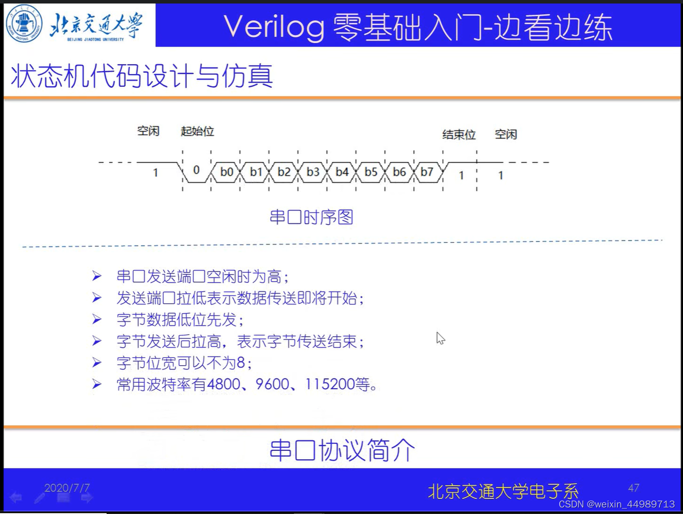
串口协议简介(来自B站-北交李金城老师的PPT,侵删)
实例1:串口数据接收
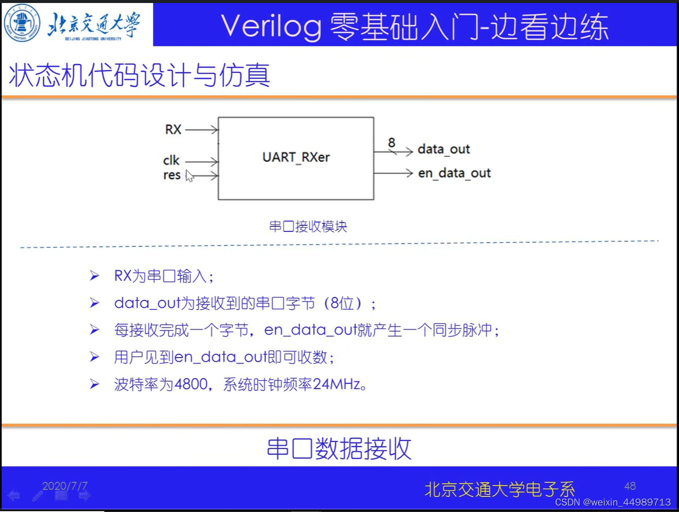
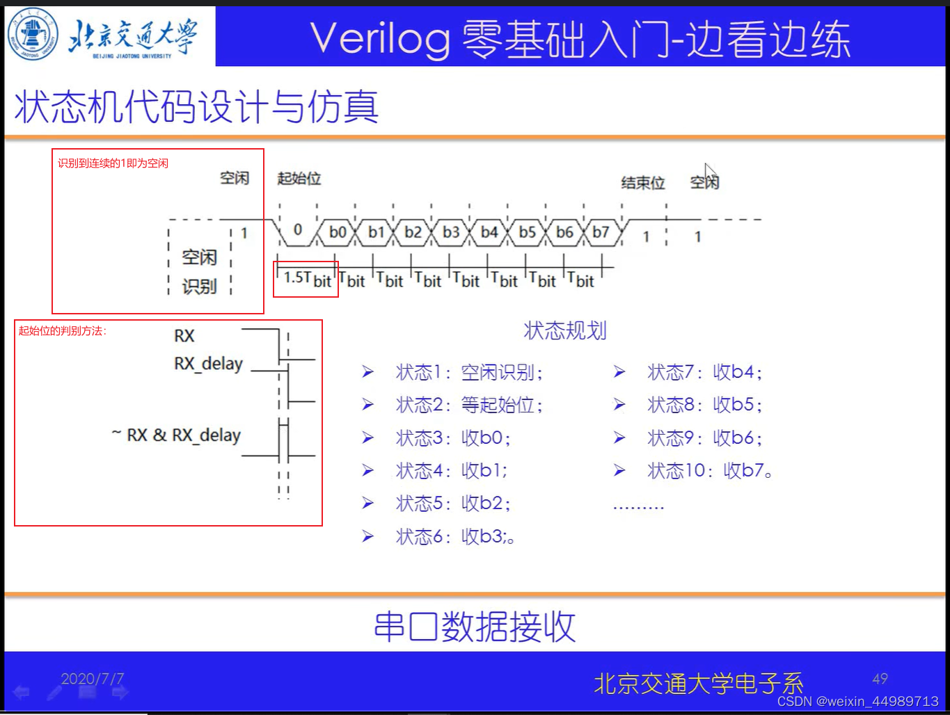
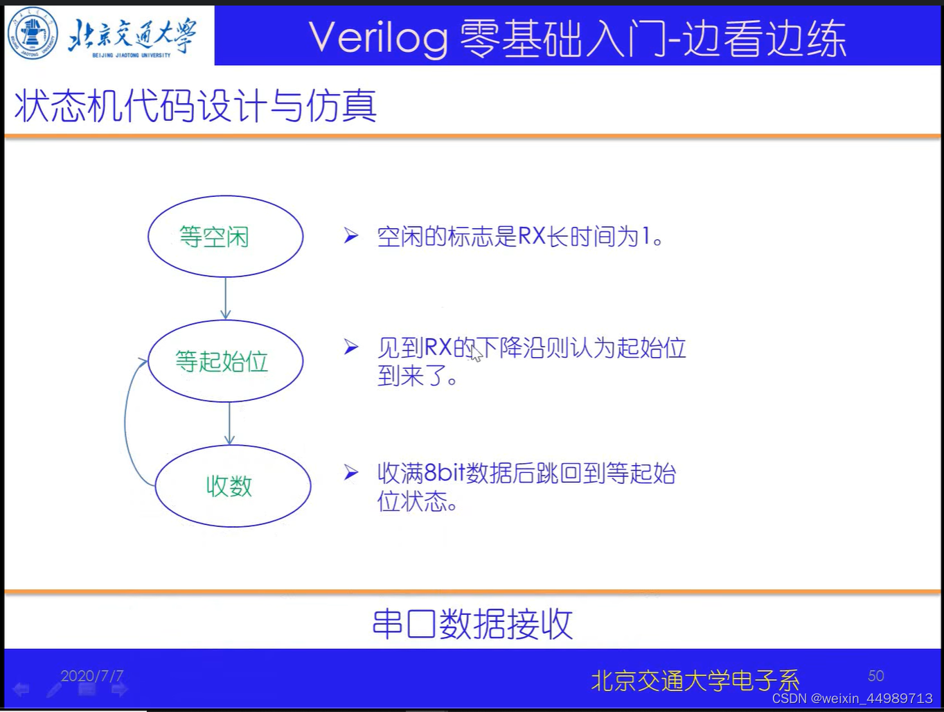
电路原理(来自B站-北交李金城老师的PPT,侵删)
代码实现与验证
完整代码:
// 串口数据接收
`timescale 1ns/10ps
// ----- 定义 -----
module serial_rec(
                    clk,
                    res,
                    RX,
                    data_out,
                    en_data_out
);

input               clk;
input               res;
input               RX;
output[7:0]         data_out; //接收字节输出
output              en_data_out; //输出使能

reg[7:0]            data_out;
reg                 en_data_out;
reg[3:0]            state; //主状态机
reg[12:0]           count; //用于计算bit宽度,24M/4800=5000,1.5bit_wide=7500
reg[3:0]            count_bits;//用于bit数的计数

reg                 RX_delay; //RX的延时

always@(posedge clk or negedge res)
if(~res)begin
    state<=0;count<=0;count_bits<=0;RX_delay<=0;
    data_out<=0;en_data_out<=0;
end
else begin
    RX_delay<=RX;

    case(state)
    0:begin //等空闲
        if(count==5000-1)begin //5000-1 !!!
            count<=0;
        end
        else begin
            count<=count+1;
        end

        if(count==0)begin
            if(RX) begin //处于空闲状态时,对bit计数
                count_bits<=count_bits+1;
            end
            else begin
                count_bits<=0;
            end
        end

        if(count_bits===12)begin // 保证处于空闲状态
            count_bits<=0;
            state<=1; // 进入state 1 ,等起始位
        end
    end
    1:begin //等起始位
        en_data_out<=0; //接收使能清零!
        if((~RX)&(RX_delay))begin //等到了脉冲尖!即RX开始拉低!
            state<=2;
        end
    end
    2:begin //经过1.5bit后开始接收数据,收最低位b0
        if(count==7500-1)begin
            count<=0;
            data_out[0]<=RX;
            state<=3;
        end
        else begin
            count<=count+1;
        end
    end
    3:begin //接收b1
        if(count==5000-1)begin
            count<=0;
            data_out[1]<=RX;
            state<=4;
        end
        else begin
            count<=count+1;
        end
    end
    4:begin //接收b2
        if(count==5000-1)begin
            count<=0;
            data_out[2]<=RX;
            state<=5;
        end
        else begin
            count<=count+1;
        end
    end
    5:begin //接收b3
        if(count==5000-1)begin
            count<=0;
            data_out[3]<=RX;
            state<=6;
        end
        else begin
            count<=count+1;
        end
    end
    6:begin //接收b4
        if(count==5000-1)begin
            count<=0;
            data_out[4]<=RX;
            state<=7;
        end
        else begin
            count<=count+1;
        end
    end
    7:begin //接收b5
        if(count==5000-1)begin
            count<=0;
            data_out[5]<=RX;
            state<=8;
        end
        else begin
            count<=count+1;
        end
    end
    8:begin //接收b6
        if(count==5000-1)begin
            count<=0;
            data_out[6]<=RX;
            state<=9;
        end
        else begin
            count<=count+1;
        end
    end
    9:begin //接收b7
        if(count==5000-1)begin
            count<=0;
            data_out[7]<=RX;
            state<=10;
        end
        else begin
            count<=count+1;
        end
    end
    10:begin //产生使能脉冲
        en_data_out<=1;
        state<=1;
    end
    default:begin
        state<=0;
        count<=0;
        count_bits<=0;
        data_out<=0;
    end
    endcase
end

endmodule

// ----- testbench -----
module serial_rec_tb;
reg                 clk,res;
wire                RX;
wire[7:0]           data_out;
wire                en_data_out;

reg[25:0]           RX_send; //!!!里面装有串口字节发送数据 16个1+起始位+数据+结束位,即16+1+8+1=26!!!
reg[12:0]           count; //对系统时钟计数,以满足波特率

assign              RX=RX_send; //连接RX!

serial_rec serial_rec(
                    .clk(clk),
                    .res(res),
                    .RX(RX),
                    .data_out(data_out),
                    .en_data_out(en_data_out)
);

initial begin
    $dumpfile("serial_rec_tb.vcd"); // save wave file
    $dumpvars(0,serial_rec);
end

initial begin
                clk<=0;res<=0;RX_send<={1'b1,8'haa,1'b0,16'hffff};count<=0;
    #17         res<=1;
    #4000000    $stop;
end

always #5 clk<=~clk;

//注意!testbench中串口发送数据的写法!!!让RX_send以波特率节奏不断右移!

always@(posedge clk)begin
    if(count==5000-1)begin
        count<=0;
    end
    else begin
        count<=count+1;
    end

    if(count==0)begin //循环右移!
        RX_send[24:0]<=RX_send[25:1];
        RX_send[25]<=RX_send[0];
    end
end

endmodule
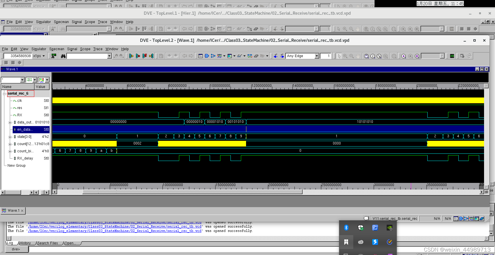
波形输出:
实例2:串口数据发送
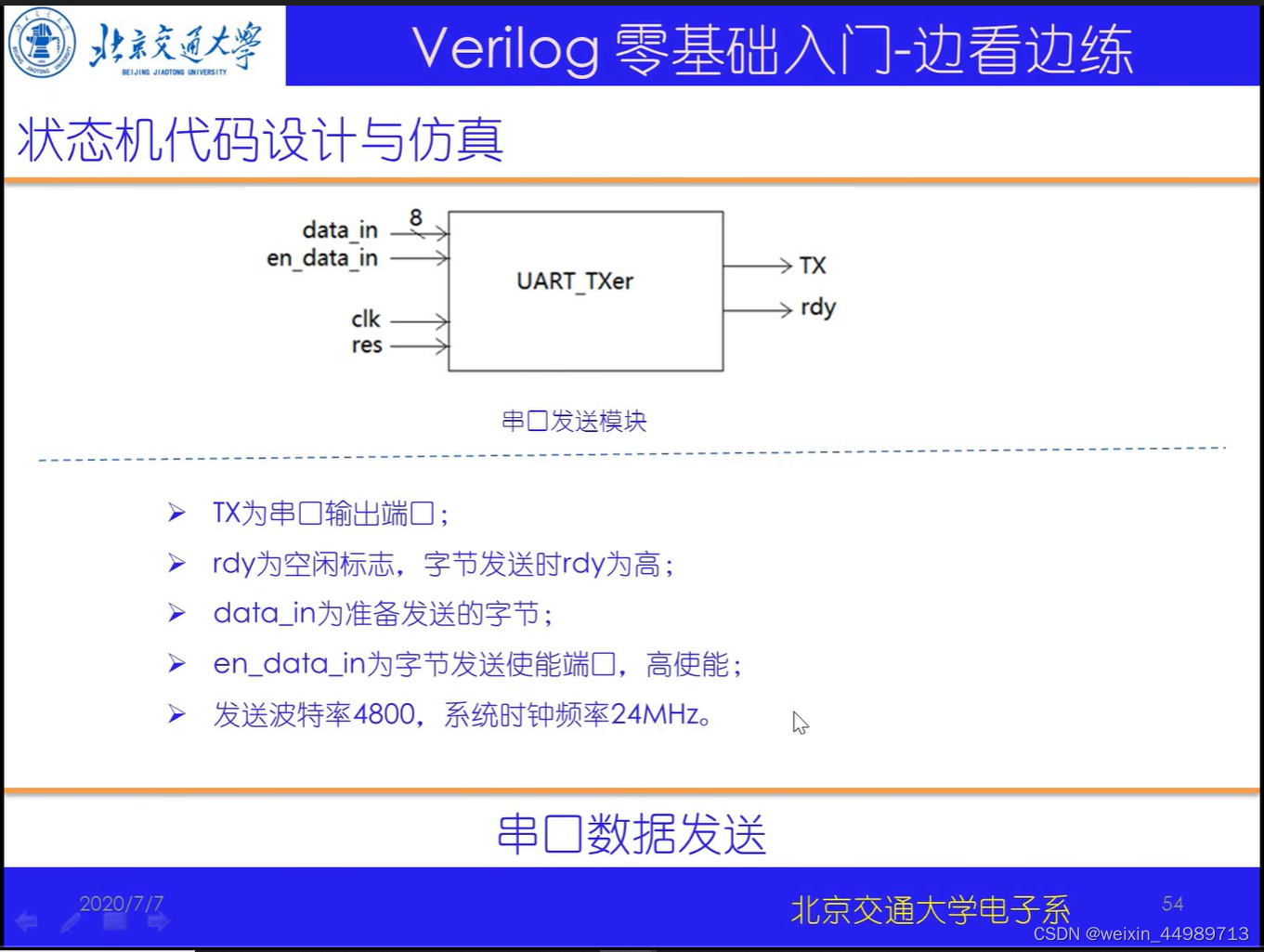
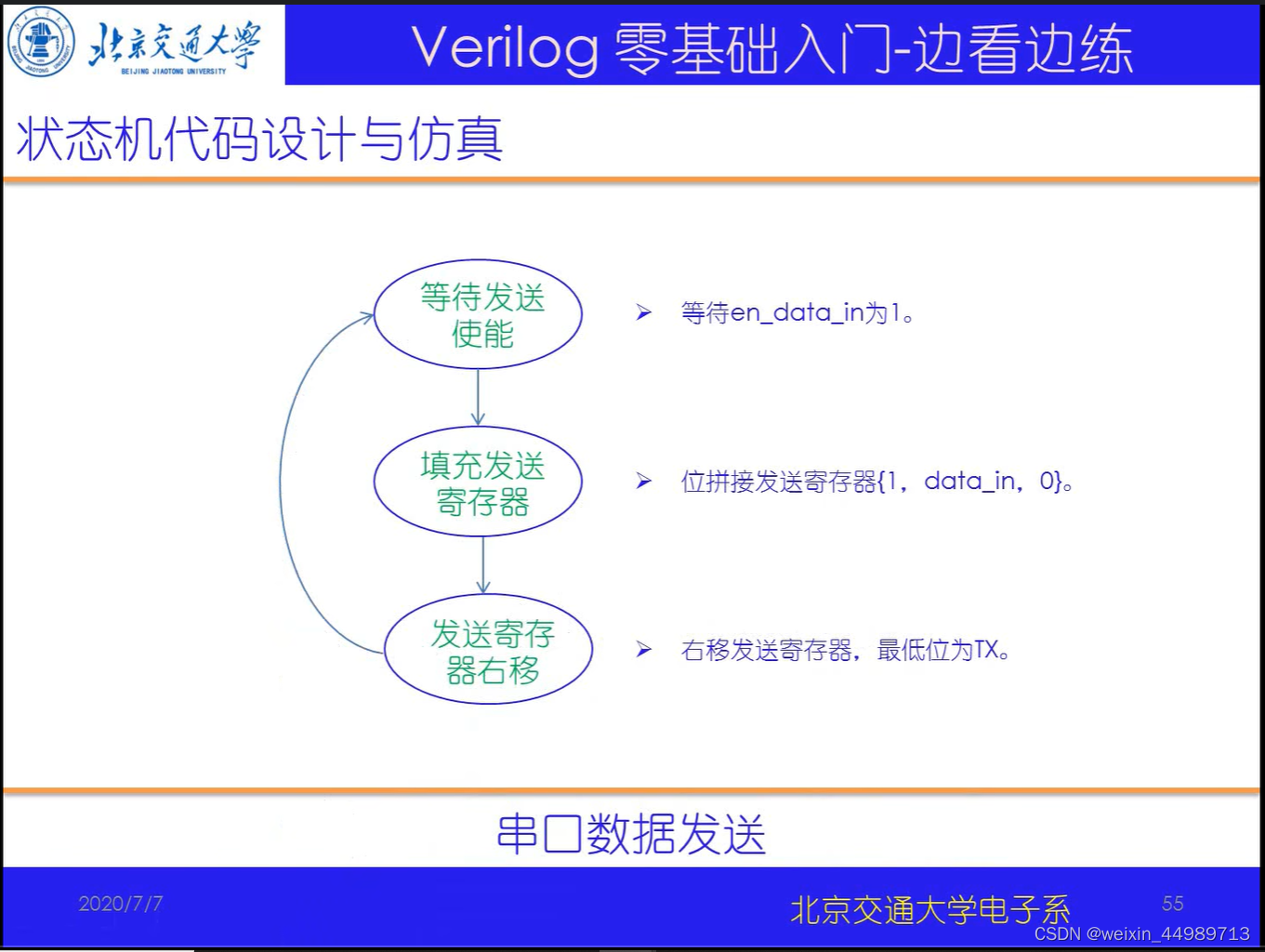
电路原理(来自B站-北交李金城老师的PPT,侵删)
代码实现与验证
代码如下:
// 串口数据发送
`timescale 1ns/1ps
module serial_send(
                    clk,
                    res,
                    data_in,
                    en_data_in,
                    TX,
                    rdy
);

input               clk;
input               res;
input[7:0]          data_in; //准备发送的数据
input               en_data_in; //发送使能
output              TX;
output              rdy; //空闲标志,0表示空闲

reg[3:0]            state; //主状态机
reg[9:0]            send_buf; //发送寄存器,存储需要发送的数据
assign              TX=send_buf[0]; //连接TX,使sned_buf不断右移,相当于TX发送

reg[9:0]            send_flag; //用于判断右移结束!10'b10_0000_0000!!!

reg[12:0]           count; //用于计数波特率

reg                 rdy; //表示空闲,防止数据发送冲突

always@(posedge clk or negedge res)
if(~res)begin
    state<=0;send_buf<=1;count<=0;send_flag<=10'b10_0000_0000;rdy<=0;
end
else begin
    case(state)
    0:begin //等使能信号
        if(en_data_in)begin
            send_buf={1'b1,data_in,1'b0}; //结束位+数据+起始位
            send_flag<=10'b10_0000_0000;
            rdy<=1;
            state<=1;
        end
    end
    1:begin //串口发送,寄存器按照波特率右移
        if(count==5000-1)begin
            count<=0;
        end
        else begin
            count<=count+1;
        end

        if(count==5000-1)begin
            send_buf[8:0]<=send_buf[9:1];
            send_flag[8:0]<=send_flag[9:1];
        end

        if(send_flag[0])begin
            rdy<=0;
            state<=0;
        end
    end
    default:begin
        state<=0;count<=0;rdy<=0;
    end
    endcase
end
endmodule

// ----- testbench -----
module serial_send_tb;
reg                 clk,res;
reg[7:0]            data_in;
reg                 en_data_in;
wire                TX;
wire                rdy;

serial_send serial_send(
                    .clk(clk),
                    .res(res),
                    .data_in(data_in),
                    .en_data_in(en_data_in),
                    .TX(TX),
                    .rdy(rdy)
);

initial begin
    $dumpfile("serial_send_tb.vcd"); // save wave file
    $dumpvars(0,serial_send);
end

initial begin
                clk<=0;res<=0;data_in<=8'h0a;en_data_in<=0;
    #17         res<=1;
    #30         en_data_in<=1;
    #10         en_data_in<=0;

    #9000000    $stop;
end

always #5 clk=~clk;

endmodule
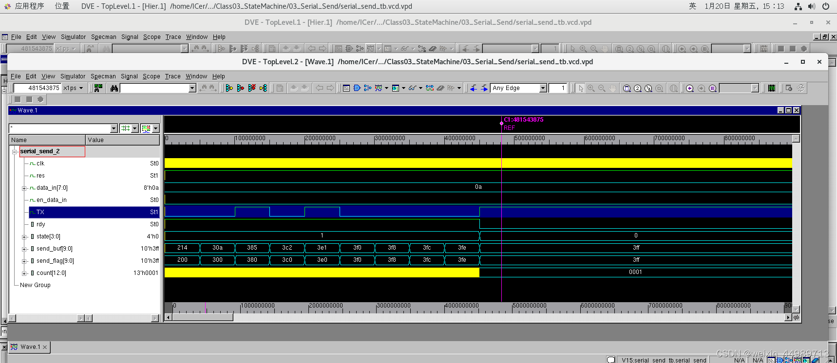
验证结果如下:
实例3:串口指令处理器
电路原理(来自B站-北交李金城老师的PPT,侵删)
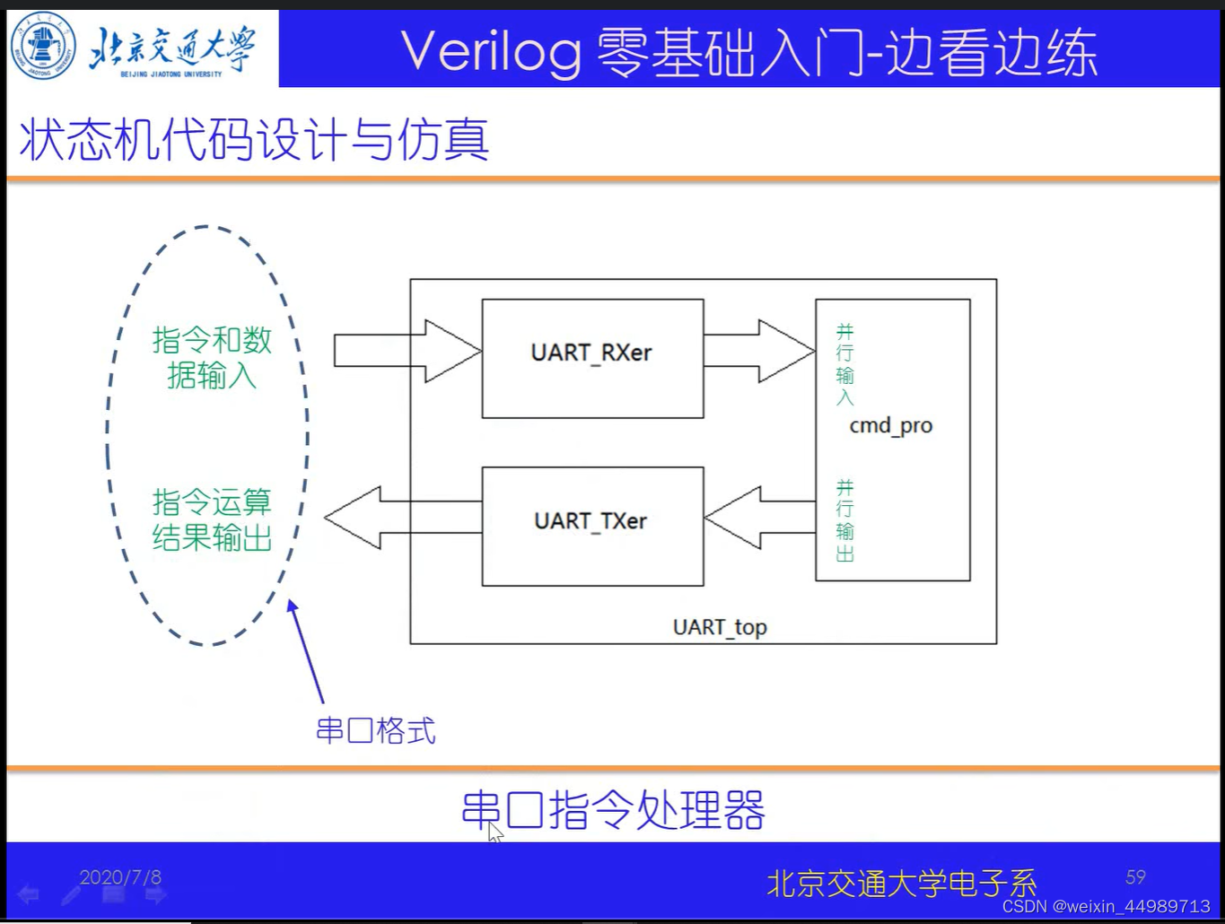
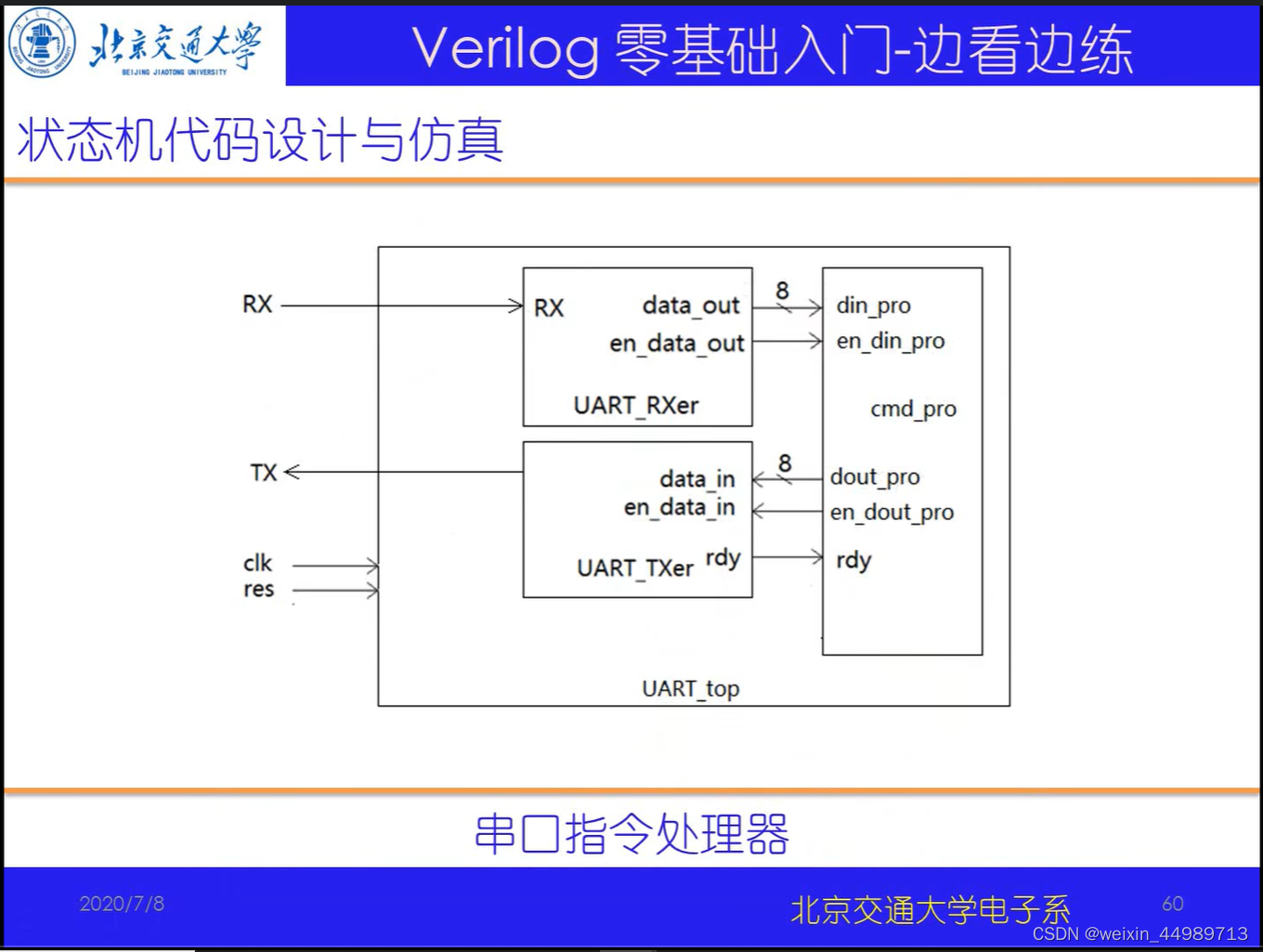
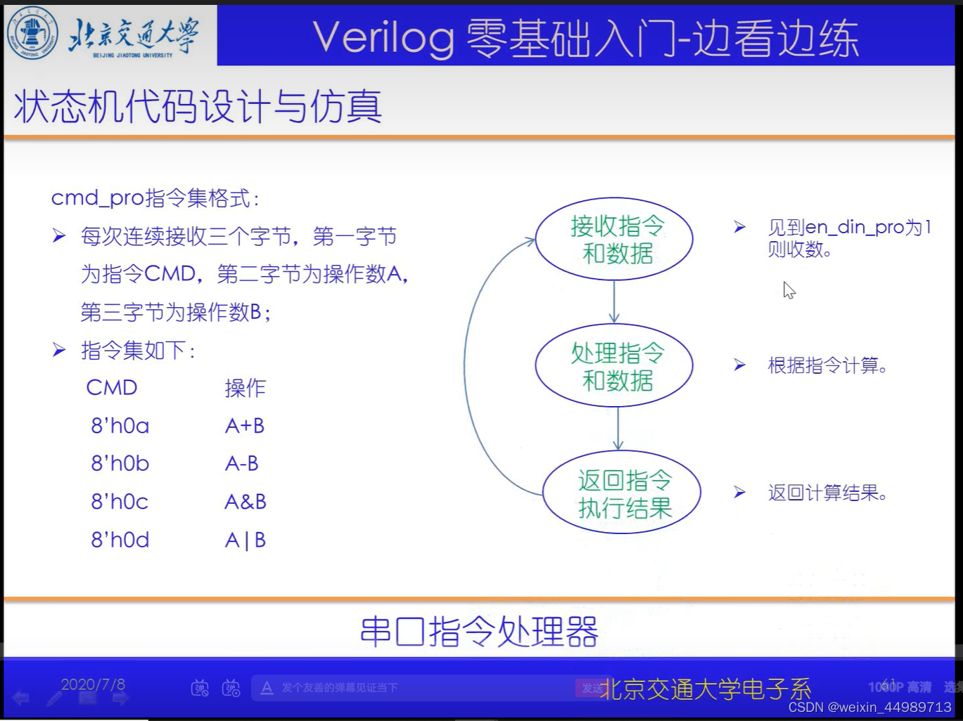
代码实现
完整代码:
serial_amd_pro.v
// 串口指令处理器
`timescale 1ns/10ps
// ----- 定义 -----
module cmd_pro(
                clk,
                res,
                din_pro,
                en_din_pro,
                dout_pro,
                en_dout_pro,
                rdy
);

input           clk;
input           res;
input[7:0]      din_pro; //指令和数据输入端口
input           en_din_pro; //输入使能
output[7:0]     dout_pro; //指令执行结果
output          en_dout_pro; //指令输出使能
output          rdy; //串口发送模块空闲标志,0表示空闲

parameter       add_AB=8'h0a; //指令集!
parameter       sub_AB=8'h0b;
parameter       and_AB=8'h0c;
parameter       or_AB=8'h0d;

reg[3:0]        state; //主状态机
reg[7:0]        cmd_reg,A_reg,B_reg; //存放指令、数据A、数据B
reg[7:0]        dout_pro;

reg             en_dout_pro;

always@(posedge clk or negedge res)
if(~res)begin
    state<=0;cmd_reg<=0;A_reg<=0;B_reg<=0;dout_pro<=0;en_dout_pro<=0;
end
else begin
    case(state)
    0:begin //等指令
        en_dout_pro<=0;
        if(en_din_pro)begin
            cmd_reg<=din_pro;
            state<=1;
        end
    end
    1:begin //收数据A
        if(en_din_pro)begin
            A_reg<=din_pro;
            state<=2;
        end
    end
    2:begin //收数据B
        if(en_din_pro)begin
            B_reg<=din_pro;
            state<=3;
        end
    end
    3:begin //根据指令进行处理,即指令译码和执行
        state<=4;
        case(cmd_reg)
            add_AB:begin dout_pro<=A_reg+B_reg;end
            sub_AB:begin dout_pro<=A_reg-B_reg;end
            and_AB:begin dout_pro<=A_reg&B_reg;end
            or_AB:begin dout_pro<=A_reg|B_reg;end
        endcase
    end
    4:begin //发送指令执行结果
        if(~rdy)begin
            en_dout_pro<=1;
            state<=0;
        end
    end
    default:begin
        state<=0;
    end
    endcase
end

endmodule
实例综合:顶层模块封装与验证
电路原理(来自B站-北交李金城老师的PPT,侵删)

makefile
makefile(在cmd中输入make compile即可执行命令)
compile:
	vcs *.v ../04_Serial_Amd_Pro/*.v ../03_Serial_Send/*.v ../02_Serial_Receive/*.v -R -timescale=1ns/10ps +v2k +define+RTL_SAIF
代码实现与验证
完整代码:
UART_top.v
//串口指令处理器
module UART_top(
                clk,
                res,
                RX,
                TX
);

input           clk;
input           res;
input           RX;
output          TX;

wire[7:0]       din_pro; // 定义5个中间信号以连接子模块(从顶层看,一定是wire)
wire            en_din_pro;
wire[7:0]       dout_pro;
wire            en_dout_pro;
wire            rdy;


serial_send serial_send( //实例化3个子模块,并进行连接,注意!top层只进行连接,不进行逻辑操作
                    .clk(clk),
                    .res(res),
                    .data_in(dout_pro),
                    .en_data_in(en_dout_pro),
                    .TX(TX),
                    .rdy(rdy)
);

serial_rec serial_rec(
                    .clk(clk),
                    .res(res),
                    .RX(RX),
                    .data_out(din_pro),
                    .en_data_out(en_din_pro)
);

cmd_pro cmd_pro(
                .clk(clk),
                .res(res),
                .din_pro(din_pro),
                .en_din_pro(en_din_pro),
                .dout_pro(dout_pro),
                .en_dout_pro(en_dout_pro),
                .rdy(rdy)
);

endmodule

// ----- testbench -----
module UART_top_tb;
reg             clk,res;
wire            RX;
wire            TX;

reg[45:0]       RX_send; //!!!里面装有串口字节发送数据 16个1+起始位+数据+结束位,即16+1+8+1=26!!!当有3个字节数据时,为16+10+10+10=46bit位宽
assign          RX=RX_send; //连接RX
reg[12:0]       count; //对系统时钟计数,以满足波特率

UART_top UART_top( //同名例化
                clk,
                res,
                RX,
                TX
);

initial begin
    $dumpfile("UART_top_tb.vcd"); // save wave file
    $dumpvars(0,UART_top);
end

initial begin
            clk<=0;res<=0;
            RX_send<={1'b1,8'h09,1'b0,1'b1,8'h06,1'b0,1'b1,8'h0a,1'b0,16'hffff};
            count<=0;
    #17     res<=1;
    #4000000    $stop;
end

always #5 clk<=~clk;

//注意!testbench中串口发送数据的写法!!!让RX_send以波特率节奏不断右移!

always@(posedge clk)begin
    if(count==5000-1)begin
        count<=0;
    end
    else begin
        count<=count+1;
    end

    if(count==0)begin //循环右移!
        RX_send[44:0]<=RX_send[45:1];
        RX_send[45]<=RX_send[0];
    end
end

endmodule
验证如下:
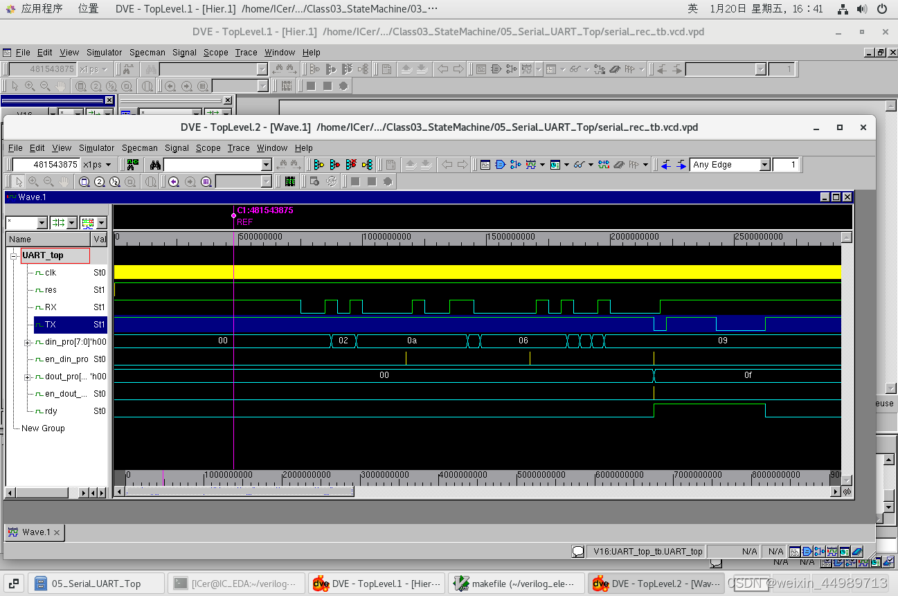
最后
以上就是懦弱黄蜂最近收集整理的关于Verilog学习脚印4-状态机(串口)bash命令串口协议简介(来自B站-北交李金城老师的PPT,侵删)实例1:串口数据接收实例2:串口数据发送实例3:串口指令处理器实例综合:顶层模块封装与验证的全部内容,更多相关Verilog学习脚印4-状态机(串口)bash命令串口协议简介(来自B站-北交李金城老师内容请搜索靠谱客的其他文章。
本图文内容来源于网友提供,作为学习参考使用,或来自网络收集整理,版权属于原作者所有。


发表评论 取消回复