Background
I2C is a straightforward serial protocol. There are usually two wires, one is for transferring data (SDA), the other is a clock which is used to mark the begin and end of data packed (SCL). Most devices will also require power (VCC) and ground (GND). There are several I2C busses on the NVIDIA Jetson AGX Xavier Kit. You can access I2C bus 8 and I2C bus 1 on the GPIO Expansion Header.
The Xavier GPIO Expansion Header is basically the same layout as the previous generation Jetson TX series. However, there is a slight difference in the software to interface with I2C devices. The Jetson TX series use a derivative of Ubuntu 16.04 (L4T 28.x), the Xavier is an Ubuntu 18.04 variant (L4T 31.x). Ubuntu 18 shifts the libi2c-dev smbus API to a separate library, and a different header file in comparison to the earlier version.
Hardware
Note:A Jetson Xavier using L4T 31.0.2 (JetPack 4.1) is shown in the demo.
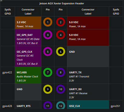
First, before powering up the Jetson, let’s wire up the LED Segment Display. Avoid wiring the Xavier when there is power connected. Here’s the pinout of the GPIO Expansion Header. In our example, we power the display from the Jetson GPIO header at 5V.
For this example project, a Adafruit 0.56″ 4-digit 7-segment Display W/i2c Backpack – Green is wired to a Jetson. The Display is assembled per the Adafruit instructions.
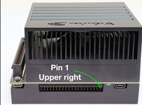
On the Jetson AGX Xavier, Pin 1 of the GPIO Expansion Header is the pin closest to the power indicator light:
Jetson AGX Xavier Pin 1


The odd number pins (right to left, pins 1,3,5 and so on) are on the top row. The bottom row is the even number pins.
On a Jetson Xavier, here’s the wiring combination for I2C Bus 8:
GND Pin 6 -> LED Backpack (GND)
VCC Pin 2 -> LED Backpack (VCC – 5V)
SDA Pin 3 -> LED Backpack (SDA)
SCL Pin 5 -> LED Backpack (SCL)
Note that the Xavier also has a I2C Bus 1 interface. See the Xavier GPIO Pinout Diagram.
If you wish to interface with I2C Bus 1:
GND Pin 6 -> LED Backpack (GND)
VCC Pin 2 -> LED Backpack (VCC – 5V)
SDA Pin 27 -> LED Backpack (SDA)
SCL Pin 28 -> LED Backpack (SCL)
Note: To use Bus 1 with the example, you will need to modify the example source code.
Software Installation
Once the board is wired up, turn the Jetson on.
Install the libi2c-dev library. In order to be able inspect the LED Display, you may find it useful to also install the i2c tools:
$ sudo apt-get install libi2c-dev i2c-tools
After installation, in a Terminal execute (8 is the I2C bus in this case):
$ sudo i2cdetect -y -r 8
ubuntu@tegra-ubuntu:~$ sudo i2cdetect -y -r 8
0 1 2 3 4 5 6 7 8 9 a b c d e f
00: — — — — — — — — — — — — —
10: — — — — — — — — — — — — — — — —
20: — — — — — — — — — — — — — — — —
30: — — — — — — — — — — — — — — — —
40: — — — — — — — — — — — — — — — —
50: — — — — — — — — — — — — — — — —
60: — — — — — — — — — — — — — — — —
70: 70 — — — 74 — — —
You should see an entry of 0x70, which is the default address of the LED Segment Display. Note that if you have soldered the address pins on the Display to change the address, you should see the appropriate address.
Next, install the library and example code which is available in the JHLEDBackpack repository on the JetsonHacks Github account. As of this writing, the Xavier version is in the L4T31 branch of the repository. There is a tagged release version for the Xavier in the v2.0 tag of the repository. To install:
$ git clone https://github.com/jetsonhacks/JHLEDBackpack.git
$ cd JHLEDBackpack
$ git checkout v2.0
$ cd example
You are then ready to compile the example and run it.
$ make
$ sudo ./displayExample
The display will go through a couple of examples, a blinking set of dashes, a hexadecimal display, a floating point number display, a count down timer and a clock example. Hit the ‘Esc’ key during the clock example to end the demo.
The source library defaults to I2C Bus 1. When we use bus 8 as in our example, displayExample.cpp reads:
HT16K33 *displayMatrix = new HT16K33() ;
// Default I2C Bus 1
// Bus 8 for Xavier Expander Header pins 3,5
displayMatrix->kI2CBus = 8;
int err = displayMatrix->openHT16K33();
Note: If you wish to use Pin 27 and 28, change the kI2CBus to 1. Make sure you save the file, and run make on it.
More Notes
Equipment and Supplies
The segmented LED display is a kit. You will need some elementary soldering skills for assembly. We tend to use:
- A soldering iron: Hakko FX888D-23BY Digital Soldering Station. The tip on the soldering iron used is the one included with the product.
- Solder, in the video 60/40 lead free solder was used.
Note: For the lead free solder, the iron was set at 750 degrees fahrenheit.
Note: A fan or fume extractor (such as the Hakko FA400-04 Bench Top ESD-Safe Smoke Absorber) should be used to avoid breathing soldering fumes. - Breadboard (In the video, a Solderless BreadBoard, 400 tie-points, 4 power rails was used)
- We also used some M/F breadboard jumper wire
New to electronics? This is a pretty easy project, looky here: Electronics Tutorials for some introductory material on how to start becoming a master.
Conclusion
Accessing the I2C bus on the Jetson AGX Xavier GPIO Expansion Header is straightforward, and makes for easy prototyping!
最后
以上就是贪玩玉米最近收集整理的关于Jetson Xavier i2c 操作的全部内容,更多相关Jetson内容请搜索靠谱客的其他文章。


发表评论 取消回复