基于simulink的s-function的PWM生成
simulink真是无所不能,不仅可以仿真电路,生成代码,还可以将自己的代码放在仿真里运行,这里基于sfun写一个PWM生成器,便于sfun的学习
模型
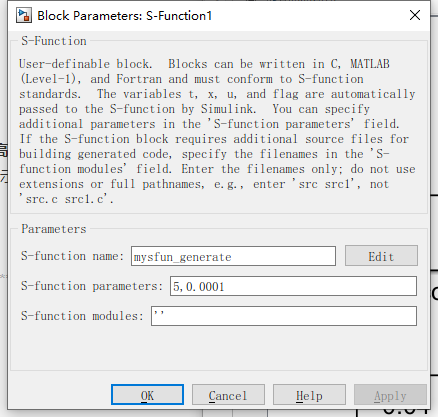
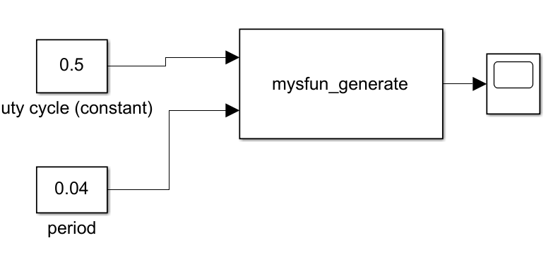
设置sfun的函数名和参数,其中有两个参数和两个输入信号,
两个参数分别是输出波形的幅值和模型运行的分辨率,这里设置幅值为5,分辨率为10k
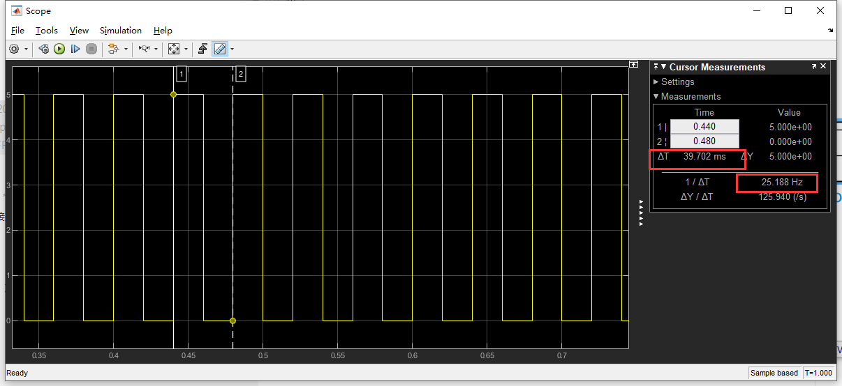
两个输入信号分别是占空比和周期值,这里设置占空比为50%,周期为40ms(25hz)
注:分辨率要大于PWM的周期值


仿真结果如下:
代码
/*
 * File     : sfun_pwm.c
 * Abstract:
 *
 *   This file represents an S-function example which demonstrates the S-function macros for using a
 *   controllable sample time. This S-function generates PWM (Pulse-width modulation) signals based
 *   on the input period and duty cycle signals.
 *
 *   This S-function registers a controllable sample time with which the S-function can schedule the
 *   next hit when changing the output value. The S-function has two input ports and one output
 *   port. The first input port is the duty cycle signal and the second is the period signal. The
 *   S-function has two block parameters: the amplitude of the generated PWM signal and the
 *   resolution of the controllable sample time.
 *
 *   This S-function illustrates the use of the S-function macro:
 *
 *        ssSetControllableSampleTime(S, 0, resolution)
 *
 *   to register a controllable sample time in mdlInitializeSampleTimes(). The resolution must be a
 *   positive finite number that defines the fundamental step size that the S-function can schedule
 *   the next hit for this sample time.
 *
 *   This S-function illustrates the use of the S-function macro:
 *
 *       ssSetNumTicksToNextHitForControllableSampleTime(S, 0, numTick)
 *
 *   to schedule the next hit of the controllable sample time. The next hit happens after t =
 *   t_current + numTick * resolution. numTick must be a positive integer. The S-function must use
 *   this macro to schedule the execution of the controllable sample time in
 *   mdlInitializeConditions() and mdlOutputs().
 *
 * Copyright 2017 The MathWorks, Inc.
 */

#define S_FUNCTION_NAME mysfun_generate                          //函数名
#define S_FUNCTION_LEVEL 2                                       //sfun的深度

#include "simstruc.h"
#include "assert.h"

/* Function: mdlInitializeSizes ================================================
 * Abstract:
 *
 *   Register an S-function with two input ports, one output port, and three DWorks. Specify the
 *   number of sample times to 1.
 *
 */
static void mdlInitializeSizes(SimStruct* S)
{
    //这个函数用来初始化的,主要是设置输入、输出和参数的。

    if (!ssSetNumInputPorts(S, 2)) return;//设置输入信号2个
    ssSetInputPortWidth(S, 0, 1);//设置输入变量0的维数为1
    ssSetInputPortDirectFeedThrough(S, 0, 1);// 设置输入端口的信号是否mdlOutputs函数中使用,这儿设置为true
    ssSetInputPortWidth(S, 1, 1);//设置输入变量1的维数为1
    ssSetInputPortDirectFeedThrough(S, 1, 1);// 设置输入端口的信号是否mdlOutputs函数中使用,这儿设置为true

    if (!ssSetNumOutputPorts(S, 1)) return;//设置输出变量的个数
    ssSetOutputPortWidth(S, 0, 1);//设置输出变量0的维数为1维

    ssSetNumSFcnParams(S, 2);//设置参数2个
    if (ssGetNumSFcnParams(S) != ssGetSFcnParamsCount(S)) {
        return;
    }

    ssSetNumContStates(S, 0);//设置连续状态变量的
    ssSetNumDiscStates(S, 0);
    ssSetNumDWork(S, 3);
    ssSetDWorkWidth(S, 0, 1);//设置离散状态变量的
    ssSetDWorkDataType(S, 0, SS_BOOLEAN);
    ssSetDWorkWidth(S, 1, 1);
    ssSetDWorkDataType(S, 1, SS_DOUBLE);
    ssSetDWorkWidth(S, 2, 1);
    ssSetDWorkDataType(S, 2, SS_UINT32);

    ssSetNumSampleTimes(S, 1);//设置采样时间,此处为1s,后面有修改

    ssSetOperatingPointCompliance(S, USE_DEFAULT_OPERATING_POINT);

    ssSetOptions(S, SS_OPTION_EXCEPTION_FREE_CODE |
                    SS_OPTION_USE_TLC_WITH_ACCELERATOR);//默认
}

/* Function: mdlInitializeSampleTimes ==========================================
 * Abstract:
 *   Register a controllable sample time with the specified resolution.
 */
static void mdlInitializeSampleTimes(SimStruct* S)
{
    real_T resolution = (real_T) *mxGetPr(ssGetSFcnParam(S,1));//设置采样时间
    ssSetControllableSampleTime(S, 0, resolution);//将参数分辨率设置成采样时间
}

/* Function: mdlInitializeConditions============================================
 * Abstract:
 *   Initialize the DWorks related to the generation of the PWM signals. Force a hit for the
 *   controllable sample time.
 */
#define MDL_INITIALIZE_CONDITIONS
static void mdlInitializeConditions(SimStruct *S)
{
    //初始化离散状态变量的值
    /*
     * Force a sample hit whenever the system is initialized.
     */
    ssSetNumTicksToNextHitForControllableSampleTime(S, 0, 1);

    boolean_T * x1  = (boolean_T*)ssGetDWork(S,0);
    real_T *x2 = (real_T*)ssGetDWork(S,1);
    uint32_T *x3 = (uint32_T*)ssGetDWork(S,2);
    *x1 = true;
    *x2 = 0.0;
    *x3 = 0;
 }

/* Function: mdlOutputs ========================================================
 * Abstract:
 *   Generate the PWM signals based on the input duty cycle and period signals.
 */
static void mdlOutputs(SimStruct* S, int_T tid)
{
    //这个函数就是输出的函数,所有的代码动作在这里执行

    real_T* y = ssGetOutputPortRealSignal(S, 0);//获取输出端口
    boolean_T* x1 = (boolean_T*)ssGetDWork(S,0);//获取离散变量端口
    real_T *x2 = (real_T*)ssGetDWork(S,1);//获取离散变量端口
    uint32_T *x3 = (uint32_T*)ssGetDWork(S,2);    //获取离散变量端口

    size_t numTicksToNextHit = 0;//设置值
    real_T yout_value = 0.0;

    if (*x1) {
        real_T amplitude_prm = (real_T) *mxGetPr(ssGetSFcnParam(S,0));
        real_T period_prm = (real_T) *mxGetPr(ssGetSFcnParam(S,1));

        InputRealPtrsType uPtrs = ssGetInputPortRealSignalPtrs(S,0);
        real_T duty = *uPtrs[0];

        real_T p = *uPtrs[1];
        size_t numSamples = (size_t) (p/period_prm);
        numTicksToNextHit = (size_t) (duty*numSamples);

        if (numTicksToNextHit == 0) {
            numTicksToNextHit = numSamples;
            yout_value = 0;
        } else if (numTicksToNextHit == numSamples) {
            numTicksToNextHit = numSamples;
            yout_value = amplitude_prm;
        } else {
            *x1 = false;
            *x2 = duty;
            *x3 = (uint32_T)(numSamples - numTicksToNextHit);
            yout_value = amplitude_prm;
        }
    } else {
        *x1 = true;
        numTicksToNextHit = (size_t) *x3;
        yout_value = 0;
    }

    *y = yout_value;//输出
    ssSetNumTicksToNextHitForControllableSampleTime(S, 0, numTicksToNextHit);    //更新下一次的采样时间

} /* mdlOutputs */

static void mdlTerminate(SimStruct *S)
{
}

/* Required S-Function trailer */

#ifdef  MATLAB_MEX_FILE    /* Is this file being compiled as a MEX-file? */
#include "simulink.c"      /* MEX-file interface mechanism */
#else
#include "cg_sfun.h"       /* Code generation registration function */
#endif
仿真文件地址
最后
以上就是懵懂缘分最近收集整理的关于基于simulink的s-function的PWM生成的全部内容,更多相关基于simulink内容请搜索靠谱客的其他文章。
本图文内容来源于网友提供,作为学习参考使用,或来自网络收集整理,版权属于原作者所有。


发表评论 取消回复