ADS1247/1248单次采集程序
单次转换命令

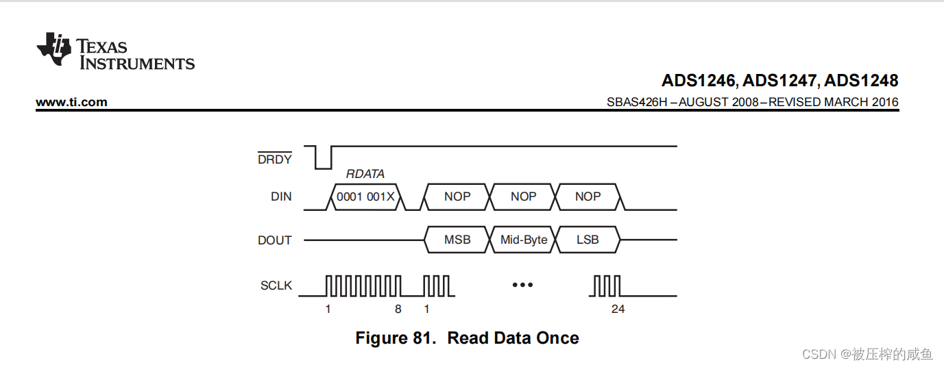
手册说的很清楚,发送转换命令RDATA后跟3个NOP的指令,通过发送24个SCLK信号来读取转换结果,这个速度取决于你SPI的速度,当然在这之前你需要配置好ADC的寄存器以及拉高START线,不明白的地方请参与我发布的ADS1247/1248配置说明,程序编写起来也很简单:
/*
Name:void ADS1248_Stop(void)

----------------------
Des:    获取ADC数据
Ref:
Paras:
Author: 咸鱼
Date:   2022年09月14日
*/
uint8_t  Buf[4] = {0};
int32_t ADS1248_Read(void)
{
    /*定义发送的读取指令,后面三个是空操作等待ADC相应*/
	uint8_t  Cmd[4]={ADS1248_CMD_RDATAC,ADS1248_CMD_NOP,ADS1248_CMD_NOP,ADS1248_CMD_NOP};
	int32_t  i32Data = 0;
    int32_t  i32Data0 = 0;
    int32_t  i32Data1 = 0;
    int32_t  i32Data2 = 0;

    /*开启转换*/
	ADS1248_SET_START;
    /*等待转换结束*/
	if(ADS1248_Wait() == 0)
    {
        ADS1248_CLR_CS;
        /*读取ADC数据保存在BUF中*/
		HAL_SPI_TransmitReceive(&hspi3,Cmd,Buf,4,HAL_MAX_DELAY);
		ADS1248_SET_CS;
	    ADS1248_CLR_START;
		/*24位ADC数据进行拼接*/
        if((Buf[0] & 0x80) == 0x80)
        {
            i32Data = 0;
            return i32Data;
        }
        else
        {
            i32Data0 = Buf[0];
            i32Data0 = i32Data0 << 16;
            i32Data1 = Buf[1];
            i32Data1 = i32Data1 << 8;
            i32Data2 = Buf[2];
		    i32Data = i32Data0 + i32Data1 + i32Data2;
		    return i32Data;
        }
    }
    else
    {
        return 0;
    }
}
在这个程序中,遵循手册的要求,首先开启转换,也就是拉高START,然后等待转换结束,也就是等待DRDY信号线产生下降沿,当ADS在DRDY产生下降沿就代表转换完成,此时直接对数据进行采集,首先把CS拉低,然后通过SPI总线发送RDATA,后面跟三个NOP的空操作,需要注意,这里的空操作也是ADS的一个指令,具体我会H文件贴在最后,然后拉高CS片选,在拉低START结束转换,此时,ADS数据就会存在事先定义好的BUF中,然后对数据进行拼接,因为ADS是24位的ADC,最高位是符号位,最大值也就是2的23次方,因为我使用的是差分信号,所以我对负值进行了抛弃,大家复制下面else部分就行,对数据进行拼接后直接返回,等待第二次读取的时候就会重新拉低START等待ADC的转换,此时,就完成了ADS的单次数据获取。
连续转换命令
连续转换也是本文的重点,在这里着重对其进行说明,因为之前一直没有搞定连续转换,测出来实际的转换速度与实际速度不匹配头疼了好久- -,所以重点说说。
首先看看手册
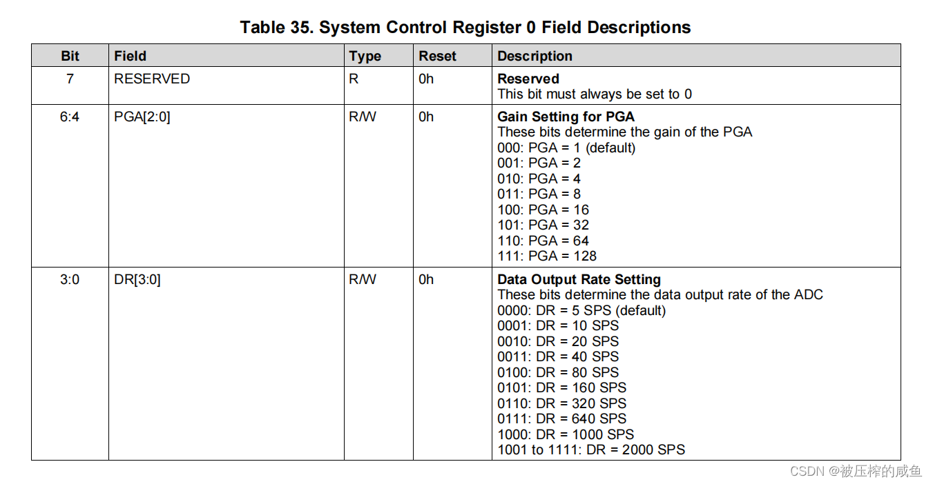
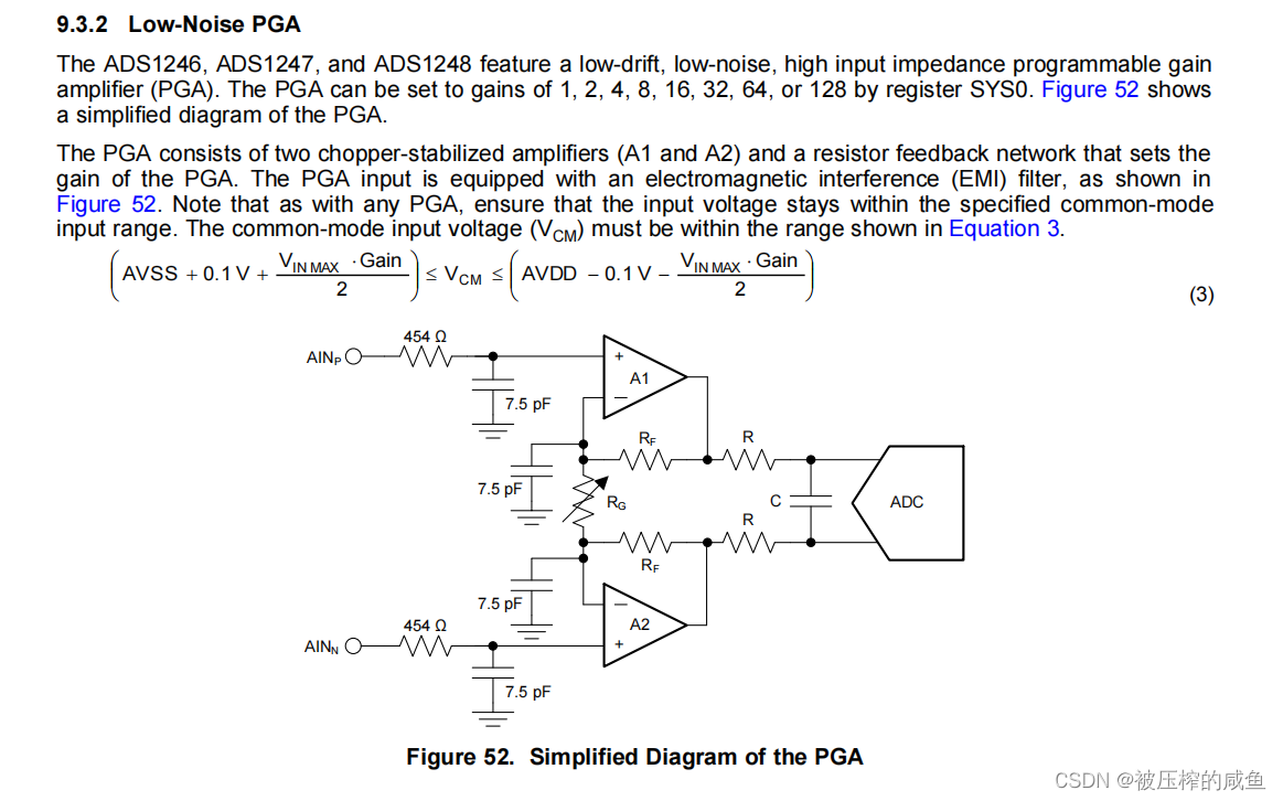
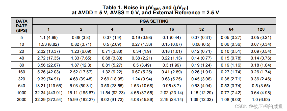
首先ADS内部有低噪声的增益放大器,这个放大器由SYS0这个寄存器进行配置,可以最大放大128倍,各位按照自己需求进行放大,
转换速率分别为5SPS,10SPS,20SPS,40SPS,80SPS,160SPS,320SPS,640SPS,1KSPS,2KSPS,当然,转换速度越高,增益越大,噪声也就越大,
我使用的是64倍增益放大,160的转换速率,所以转换一次时间大约为6.25ms。
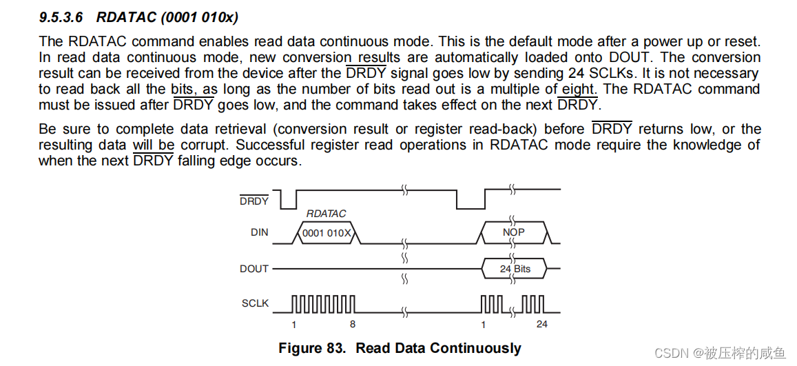
根据手册来编写程序:RDATAC命令可启用读取数据连续模式。这是上电或重置后的默认模式。在读取数据连续模式下,新的转换结果会自动加载到DOUT上。在DRDY信号降低后,可以通过发送24个SCLKs从设备接收到转换结果。请确保在DRDY返回低值之前完成数据检索(转换结果或寄存器回读),否则产生的数据将被损坏。在RDATAC模式下成功的寄存器读取操作需要知道下一个DRDY下降沿何时发生。
下面贴上整个ADS的驱动
/*
Name:void ADS1248_Init(void)

----------------------
Des:    ADS1248初始化
Ref:
Paras:
Author:
Date:
*/
void ADS1248_Init(void)
{
    uint8_t Cmd = 0;
    /*对ADC进行复位*/
    ADS1248_Reset();
    HAL_Delay(20);
    /*配置MUX0寄存器AIN0为正输入,AIN1为负输入*/
//    Cmd = 0x08;/*0000 0001*/
//    ADS1248_WriteReg(ADS1248_MUX0,&Cmd,1);
    /*打开AN0/AIN1偏置电压*/
//    Cmd = 0x03;/*0000 0001*/
//    ADS1248_WriteReg(ADS1248_VBIAS,&Cmd,1);
    /*配置MUX1使用内部2.048基准、打开内部基准源*/
    Cmd=0x30 ;/*0 01 00 000*/
    ADS1248_WriteReg(ADS1248_MUX1,&Cmd,1);
    /*配置SYS0寄存器PGA为放大64倍,输出速率为160SPS*/
    Cmd=0x65 ;/*0110 0010*/
    ADS1248_WriteReg(ADS1248_SYS0,&Cmd,1);
    /*配置IDAC0不使能DRDY、关闭激励*/
    Cmd=0x00 ;/*0000 0000*/
    ADS1248_WriteReg(ADS1248_IDAC0,&Cmd,1);
    /*配置IDAC1寄存器不选择励磁电流源引脚、不使能引脚*/
    Cmd=0xFF;/*1111 1111*/
    ADS1248_WriteReg(ADS1248_IDAC1,&Cmd,1);
    /*配置FSC0为00*/
    Cmd=0x00;/*0010 0000*/
    ADS1248_WriteReg(ADS1248_FSC0,&Cmd,1);
    /*配置FSC1为00*/
    Cmd=0x00;/*0000 0000*/
    ADS1248_WriteReg(ADS1248_FSC1,&Cmd,1);
    /*配置FSC2为40,在公式中需要除以常数0x400000*/
    Cmd=0x40;/*0000 0100*/
//    ADS1248_WriteReg(ADS1248_FSC2,&Cmd,1);
    HAL_Delay(20);
    /*拉高START准备ADC转换*/
    ADS1248_CLR_START;
    ADS1248_WriteCommand(ADS1248_CMD_SYSOCAL);
    HAL_Delay(20);
    ADS1248_WriteCommand(ADS1248_CMD_SYSGCAL);
    HAL_Delay(20);
    ADS1248_WriteCommand(ADS1248_CMD_SELFOCAL);
    HAL_Delay(20);
	/*启动连续转换命令*/
    ADS1248_WriteCommand(ADS1248_CMD_RDATAC);
    HAL_Delay(20);
}
/*
Name:ADS1248_ReadReg(uint8_t RegAddr,uint8_t *Buffer,uint8_t Length)
----------------------
Des:    Ads1248读寄存器
Ref:
Paras:
Author:
Date:
*/
void ADS1248_ReadReg(uint8_t RegAddr,uint8_t *Buffer,uint8_t Length)
{
    uint8_t Cmd[2];
    ADS1248_CLR_CS;
    ADS1248_SET_START;
    /*ADS1248芯片手册规定的发送数据格式*/
    /*First Command Byte: 0010 rrrr,
      where rrrr is the address of the first register to read.*/
    Cmd[0] = ADS1248_CMD_RREG | (RegAddr & 0x0f);
    /*Second Command Byte: 0000 nnnn,
      where nnnn is the number of bytes to read –1*/
    Cmd[1] = (Length - 1) & 0x0f;
    /*发送读取指令*/
    HAL_SPI_Transmit(&hspi3,Cmd,2,HAL_MAX_DELAY);
    /*接收数据*/
    HAL_SPI_Receive(&hspi3, Buffer, Length, HAL_MAX_DELAY);
    Cmd[0] = ADS1248_CMD_NOP;
    /*接受数据时不能使用SPI的全双工,要发送nop,此为手册原句*/
    /*It is not possible to use the full-duplex nature of the
      serial interface when reading out the register data. For
      example, a SYNC command cannot be issued when reading out the
      VBIAS and MUX1 data, as shown in
      Figure 84. Any command sent during the readout of the register
      data is ignored. Thus, TI recommends sending
      NOPs through DIN when reading out the register data.*/
    HAL_SPI_Transmit(&hspi3, Cmd,1,HAL_MAX_DELAY);
    HAL_Delay(20);
    ADS1248_SET_CS;
}
/*
Name:static  void ADS1248_WriteReg(uint8_t RegAddr,uint8_t *Buffer,uint8_t Length)

----------------------
Des:    Ads1248写寄存器
Ref:
Paras:
Author:
Date:
*/
static void ADS1248_WriteReg(uint8_t RegAddr,uint8_t *Buffer,uint8_t Length)
{
    uint8_t Cmd[2];
    ADS1248_CLR_CS;
    ADS1248_SET_START;
    HAL_Delay(20);
    /*ADS1248芯片手册规定的发送数据格式*/
    /*First Command Byte: 0100 rrrr
      where rrrr is the address of the first register to be written.*/
    Cmd[0] = ADS1248_CMD_WREG | (RegAddr & 0x0F);
    /*Second Command Byte: 0000 nnnn,
      where nnnn is the number of bytes to be written – 1*/
    Cmd[1] = (Length - 1) & 0x0F;
    /*指定向指定寄存器写入指定字节数据*/
    HAL_SPI_Transmit(&hspi3, Cmd, 2,HAL_MAX_DELAY);
    /*Byte(s): data to be written to the registers.*/
    HAL_SPI_Transmit(&hspi3, Buffer, Length,HAL_MAX_DELAY);
    HAL_Delay(20);
    ADS1248_SET_CS;
    ADS1248_CLR_START;
}
/*
Name:void ADS1248_WriteCommand(uint8_t u8Command)

----------------------
Des:    Ads1248写命令
Ref:
Paras:
Author:
Date:
*/
uint8_t  Cmd[4] = {0};
void ADS1248_WriteCommand(uint8_t u8Command)
{
    Cmd[0] = u8Command;
    ADS1248_CLR_CS;
    /*读取ADC数据保存在BUF中*/
    HAL_SPI_Transmit(&hspi3, Cmd, 4,HAL_MAX_DELAY);
	HAL_Delay(10);
	ADS1248_SET_CS;
}
/*
Name:uint8_t ADS1248_Wait()

----------------------
Des:    判断忙状态
Ref:
Paras:
Author:
Date:
*/
uint8_t ADS1248_Wait()
{
    while(ADS1248_DRDY_READY > 0);
	return 0;
}
/*
Name:void ADS1248_Reset(void)

----------------------
Des:    ADS1248复位
Ref:
Paras:
Author:
Date:
*/
void ADS1248_Reset(void)
{
	ADS1248_SET_CS;
    ADS1248_SET_START;
    ADS1248_CLR_RESET;
    HAL_Delay(20);
    ADS1248_SET_RESET;
    HAL_Delay(20);
}
/*
Name:void ADS1248_Start(uint8_t CovMode)

----------------------
Des:    ADS1248开启转换
Ref:
Paras:
Author:
Date:
*/
void ADS1248_Start(uint8_t CovMode)
{
    ADS1248_SET_START;
    /*如果配置为单次转换,则将START拉低,否则则持续拉高持续转换*/
    if(CovMode == ADC_MODE_SINGLECOV)
    {
        ADS1248_CLR_START;
    }
    else
    {
        ;
    }
}
/*
Name:void ADS1248_Stop(void)

----------------------
Des:    ADS1248结束转换
Ref:
Paras:
Author:
Date:
*/
void ADS1248_Stop(void)
{
    /*停止转换*/
    ADS1248_CLR_START;
}
/*
Name:void ADS1248_Stop(void)

----------------------
Des:    获取ADC数据
Ref:
Paras:
Author:
Date:
*/
uint8_t  Buf[4] = {0};
uint8_t  SymbolBuf[1] = {0};
int32_t ADS1248_Read(void)
{
    /*发送空操作等待ADC自动读取*/
	uint8_t  Cmd[4]={ADS1248_CMD_NOP,ADS1248_CMD_NOP,ADS1248_CMD_NOP,ADS1248_CMD_NOP};
    int32_t  i32Data = 0;
    int32_t  i32Data0 = 0;
    int32_t  i32Data1 = 0;
    int32_t  i32Data2 = 0;
    int32_t  i32Data3 = 0;
    /*等待转换结束*/
	if(ADS1248_Wait() == 0)
    {
        ADS1248_CLR_CS;
        /*读取ADC数据保存在BUF中*/
		HAL_SPI_TransmitReceive(&hspi3,Cmd,Buf,4,HAL_MAX_DELAY);
		ADS1248_SET_CS;
		/*24位ADC数据进行拼接*/
        /*移植符号位*/
        SymbolBuf[0] = Buf[0] & 0x80;
        if((Buf[0] & 0x80) == 0x80)
        {
            /*移植数据位*/
            i32Data0 = Buf[0];
            i32Data0 = i32Data0 << 16;
            i32Data1 = Buf[1];
            i32Data1 = i32Data1 << 8;
            i32Data2 = Buf[2];
		    i32Data = i32Data0 + i32Data1 + i32Data2;
            i32Data = ~i32Data;
            i32Data = i32Data & 0x00FFFFFF;
            i32Data = 0 - i32Data;
        }
        else
        {
            /*移植数据位*/
            i32Data0 = Buf[0];
            i32Data0 = i32Data0 << 16;
            i32Data1 = Buf[1];
            i32Data1 = i32Data1 << 8;
            i32Data2 = Buf[2];
		    i32Data = i32Data0 + i32Data1 + i32Data2 + i32Data3;
        }
		return i32Data;
    }
    else
    {
        return 0;
    }
}
程序写的很清楚,在初始化的时候下发RDATAC连续转换命令之后一直拉高START,让ADC持续转换,持续检测DRDY引脚,当检测到下降沿之后就认为转换成功,在采集程序中持续发送NOP空操作来获取数据,获取到数据之后对数据进行处理,这里的处理是根据自身传感器去编写,可以参考单次转换的处理程序直接读出AD值,至此,连续采集就编写完成,利用示波器查看转换速率,经检测理论与实际检测吻合。
下面是H文件:
#ifndef __HH_BSP_ADS1248_H_HH__
#define __HH_BSP_ADS1248_H_HH__

#ifdef BSP_ADS1248
#define BSP_ADS1248_EX
#else
#define BSP_ADS1248_EX extern
#endif

#include "main.h"
/*其管脚连接定义*/
/*RST复位引脚*/
#define ADS1248_RST_PIN         GPIO_PIN_9
#define ADS1248_RST_GPIO        GPIOA
#define ADS1248_SET_RESET		HAL_GPIO_WritePin(ADS1248_RST_GPIO, ADS1248_RST_PIN, GPIO_PIN_SET)
#define ADS1248_CLR_RESET		HAL_GPIO_WritePin(ADS1248_RST_GPIO, ADS1248_RST_PIN, GPIO_PIN_RESET)
/*开始使能引脚*/
#define ADS1248_START_PIN       GPIO_PIN_10
#define ADS1248_START_GPIO      GPIOA
#define ADS1248_SET_START		HAL_GPIO_WritePin(ADS1248_START_GPIO, ADS1248_START_PIN, GPIO_PIN_SET)
#define ADS1248_CLR_START		HAL_GPIO_WritePin(ADS1248_START_GPIO, ADS1248_START_PIN, GPIO_PIN_RESET)
/*DRDY引脚*/
#define ADS1248_DRDY_PIN        GPIO_PIN_11
#define ADS1248_DRDY_GPIO       GPIOA
#define ADS1248_DRDY_READY		HAL_GPIO_ReadPin(ADS1248_DRDY_GPIO,ADS1248_DRDY_PIN)
/*CS片选引脚*/
#define ADS1248_CS_PIN          GPIO_PIN_15
#define ADS1248_CS_GPIO         GPIOA
#define ADS1248_SET_CS			HAL_GPIO_WritePin(ADS1248_CS_GPIO, ADS1248_CS_PIN, GPIO_PIN_SET)
#define ADS1248_CLR_CS			HAL_GPIO_WritePin(ADS1248_CS_GPIO, ADS1248_CS_PIN, GPIO_PIN_RESET)

/*压力传感器电源管理*/
#define ADS1248_POWER_ENABLE    HAL_GPIO_WritePin(GPIOB, GPIO_PIN_9, GPIO_PIN_SET)
#define ADS1248_POWER_DISABLE   HAL_GPIO_WritePin(GPIOB, GPIO_PIN_9, GPIO_PIN_RESET)

/*AD相关命令及寄存器定义*/
/*System Control Commands*/
#define ADS1248_CMD_WAKEUP		(0x00)	/* or 0x01, Exit sleep mode */
#define ADS1248_CMD_SLEEP		(0x03)	/* or 0x03, Enter sleep mode */
#define ADS1248_CMD_SYNC		(0x05)	/* or 0x05, Synchronize the A/D conversion */
#define ADS1248_CMD_RESET		(0x07)	/* or 0x07, Reset to power-up values */
#define ADS1248_CMD_NOP			(0xFF)	/* No operation */
/*Data Read Commands*/
#define ADS1248_CMD_RDATA		(0x13)	/* or 0x13, Read data once */
#define ADS1248_CMD_RDATAC		(0x15)	/* or 0x15, Read data continuously */
#define ADS1248_CMD_SDATAC		(0x17)	/* or 0x17, Stop reading data continuously */
/*Read Register Command*/
#define ADS1248_CMD_RREG		(0x20)	/* Read from register rrrr */
/*Write Register Command*/
#define ADS1248_CMD_WREG		(0x40)	/* Write to register rrrr */
/*Calibration Commands*/
#define ADS1248_CMD_SYSOCAL		(0x60)	/* System offset calibration */
#define ADS1248_CMD_SYSGCAL		(0x61)	/* System gain calibration */
#define ADS1248_CMD_SELFOCAL	(0x62)	/* Self offset calibration */
/*ADS1247 Register Map (for ADS1247 or ADS1248)*/
#define ADS1248_MUX0			(0x00)
#define ADS1248_VBIAS			(0x01)
#define ADS1248_MUX1			(0x02)
#define ADS1248_SYS0			(0x03)
#define ADS1248_OFC0			(0x04)
#define ADS1248_OFC1			(0x05)
#define ADS1248_OFC2			(0x06)
#define ADS1248_FSC0			(0x07)
#define ADS1248_FSC1			(0x08)
#define ADS1248_FSC2			(0x09)
#define ADS1248_IDAC0			(0x0A)
#define ADS1248_IDAC1			(0x0B)
#define ADS1248_GPIOCFG			(0x0C)
#define ADS1248_GPIODIR			(0x0D)
#define ADS1248_GPIODAT			(0x0E)
/* MUX0 ---------------------------------------------------------------*/
#define BCS1 		BIT7
#define BCS0 		BIT6
#define MUX_SP2 	BIT5
#define MUX_SP1 	BIT4
#define MUX_SP0 	BIT3
#define MUX_SN2 	BIT2
#define MUX_SN1 	BIT1
#define MUX_SN0		BIT0

#define BCS_0		(0x00)	/* 00 = Burnout current source off (default)*/
#define BCS_1		(0x40)	/* 01 = Burnout current source on, 0.5uA*/
#define BCS_2		(0x80)	/* 10 = Burnout current source on, 2uA*/
#define BCS_3		(0xC0)	/* 11 = Burnout current source on, 10uA*/

/* Positive:*/
#define MUX_P0		(0x00)	/* AIN0*/
#define MUX_P1		(0x08)	/* AIN1*/
#define MUX_P2		(0x10)	/* AIN2*/
#define MUX_P3		(0x18)	/* AIN3*/
#define MUX_P4		(0x20)	/* AIN4*/
#define MUX_P5		(0x28)	/* AIN5*/
#define MUX_P6		(0x30)	/* AIN6*/
#define MUX_P7		(0x38)	/* AIN7*/

/* Negative:*/
#define MUX_N0		(0x00)	/* AIN0*/
#define MUX_N1		(0x01)	/* AIN1*/
#define MUX_N2		(0x02)	/* AIN2*/
#define MUX_N3		(0x03)	/* AIN3*/
#define MUX_N4		(0x04)	/* AIN4*/
#define MUX_N5		(0x05)	/* AIN5*/
#define MUX_N6		(0x06)	/* AIN6*/
#define MUX_N7		(0x07)	/* AIN7*/

/* VBIAS ---------------------------------------------------------------*/
/* VBIAS7 ~ VBIAS4 ADS1248 only*/
#define VBIAS7 		BIT7
#define VBIAS6 		BIT6
#define VBIAS5 		BIT5
#define VBIAS4 		BIT4
#define VBIAS3 		BIT3
#define VBIAS2 		BIT2
#define VBIAS1 		BIT1
#define VBIAS0		BIT0

/* MUX1 ---------------------------------------------------------------*/
/*define CLKSTAT 	BIT7*/	/* read-only*/
#define VREFCON1 	BIT6
#define VREFCON0 	BIT5
#define REFSELT1 	BIT4
#define REFSELT0 	BIT3
#define MUXCAL2 	BIT2
#define MUXCAL1 	BIT1
#define MUXCAL0		BIT0

#define VREF_0		(0x00)	/* 00 = Internal reference is always off (default)*/
#define VREF_1		(0x20)	/* 01 = Internal reference is always on*/
#define VREF_2		(0x40)	/* 10 or 11 = Internal reference is on when a conversion is in progress and */
							/* shuts down when the device receives a shutdown opcode or the START pin is taken low*/
#define REFSELT_0	(0x00)	/* 00 = REF0 input pair selected (default)*/
#define REFSELT_1	(0x08)	/* 01 = REF1 input pair selected (ADS1248 only)*/
#define REFSELT_2	(0x10)	/* 10 = Onboard reference selected*/
#define REFSELT_3	(0x18)	/* 11 = Onboard reference selected and internally connected to REF0 input pair*/

#define MUXCAL_0	(0x00)	/* 000 = Normal operation (default)*/
#define MUXCAL_1	(0x01)	/* 001 = Offset measurement*/
#define MUXCAL_2	(0x02)	/* 010 = Gain measurement*/
#define MUXCAL_3	(0x03)	/* 011 = Temperature diode*/
#define MUXCAL_4	(0x04)	/* 100 = External REF1 measurement (ADS1248 only)*/
#define MUXCAL_5	(0x05)	/* 101 = External REF0 measurement*/
#define MUXCAL_6	(0x06)	/* 110 = AVDD measurement*/
#define MUXCAL_7	(0x07)	/* 111 = DVDD measurement*/

/* SYS0 ---------------------------------------------------------------*/
#define PGA2 		BIT6
#define PGA1 		BIT5
#define PGA0 		BIT4
#define DOR3 		BIT3
#define DOR2 		BIT2
#define DOR1 		BIT1
#define DOR0		BIT0

#define PGA_0		(0x00)	/* 000 = 1 (default)*/
#define PGA_1		(0x10)	/* 001 = 2*/
#define PGA_2		(0x20)	/* 010 = 4*/
#define PGA_3		(0x30)	/* 011 = 8*/
#define PGA_4		(0x40)	/* 100 = 16*/
#define PGA_5		(0x50)	/* 101 = 32*/
#define PGA_6		(0x60)	/* 110 = 64*/
#define PGA_7		(0x70)	/* 111 = 128*/

#define SPS_0		(0x00)	/* 0000 = 5SPS (default)*/
#define SPS_1		(0x01)	/* 0001 = 10SPS*/
#define SPS_2		(0x02)	/* 0010 = 20SPS*/
#define SPS_3		(0x03)	/* 0011 = 40SPS*/
#define SPS_4		(0x04)	/* 0100 = 80SPS*/
#define SPS_5		(0x05)	/* 0101 = 160SPS*/
#define SPS_6		(0x06)	/* 0110 = 320SPS*/
#define SPS_7		(0x07)	/* 0111 = 640SPS*/
#define SPS_8		(0x08)	/* 1000 = 1000SPS*/
#define SPS_9		(0x09)	/* 1001 to 1111 = 2000SPS*/

/*IDAC0 ---------------------------------------------------------------*/
/*#define ID3_ 		BIT7*/
/*#define ID2_ 		BIT6*/
/*#define ID1_ 		BIT5*/
/*#define ID0_ 		BIT4*/
#define MDRODDYE 	BIT3
#define IMAG2 		BIT2
#define IMAG1 		BIT1
#define IMAG0		BIT0

#define DOUTDRDY_0	(0x00)	/* 0 = DOUT/DRDY pin functions only as Data Out (default)*/
#define DOUTDRDY_1	(0x80)	/* 1 = DOUT/DRDY pin functions both as Data Out and Data Ready, active low*/

#define IMAG_0		(0x00)	/* 000 = off (default)*/
#define IMAG_1		(0x01)	/* 001 = 50uA*/
#define IMAG_2		(0x02)	/* 010 = 100uA*/
#define IMAG_3		(0x03)	/* 011 = 250uA*/
#define IMAG_4		(0x04)	/* 100 = 500uA*/
#define IMAG_5		(0x05)	/* 101 = 750uA*/
#define IMAG_6		(0x06)	/* 110 = 1000uA*/
#define IMAG_7		(0x07)	/* 111 = 1500uA*/

/*IDAC1 ---------------------------------------------------------------*/
#define I1DIR3 		BIT7
#define I1DIR2 		BIT6
#define I1DIR1 		BIT5
#define I1DIR0 		BIT4
#define I2DIR3 		BIT3
#define I2DIR2 		BIT2
#define I2DIR1 		BIT1
#define I2DIR0		BIT0

#define I1DIR_0		(0xF0)	/* 11xx = Disconnected (default)*/
#define I1DIR_1		(0x00)	/* 0000 = AIN0*/
#define I1DIR_2		(0x10)	/* 0001 = AIN1*/
#define I1DIR_3		(0x20)	/* 0010 = AIN2*/
#define I1DIR_4		(0x30)	/* 0011 = AIN3*/
#define I1DIR_5		(0x40)	/* 0100 = AIN4 (ADS1248 only)*/
#define I1DIR_6		(0x50)	/* 0101 = AIN5 (ADS1248 only)*/
#define I1DIR_7		(0x60)	/* 0110 = AIN6 (ADS1248 only)*/
#define I1DIR_8		(0x70)	/* 0111 = AIN7 (ADS1248 only)*/
#define I1DIR_9		(0x80)	/* 10x0 = IEXT1 (ADS1248 only)*/
#define I1DIR_10	(0x90)	/* 10x1 = IEXT2 (ADS1248 only)*/

#define I2DIR_0		(0x0F)	/* 11xx = Disconnected (default)*/
#define I2DIR_1		(0x00)	/* 0000 = AIN0*/
#define I2DIR_2		(0x01)	/* 0001 = AIN1*/
#define I2DIR_3		(0x02)	/* 0010 = AIN2*/
#define I2DIR_4		(0x03)	/* 0011 = AIN3*/
#define I2DIR_5		(0x04)	/* 0100 = AIN4 (ADS1248 only)*/
#define I2DIR_6		(0x05)	/* 0101 = AIN5 (ADS1248 only)*/
#define I2DIR_7		(0x06)	/* 0110 = AIN6 (ADS1248 only)*/
#define I2DIR_8		(0x07)	/* 0111 = AIN7 (ADS1248 only)*/
#define I2DIR_9		(0x08)	/* 10x0 = IEXT1 (ADS1248 only)*/
#define I2DIR_10	(0x09)	/* 10x1 = IEXT2 (ADS1248 only)*/

#define ADS1248_DELAY		HAL_Delay(2)
/*ADS1248转换模式*/
#define ADC_MODE_SINGLECOV      0x00 /*单次转换*/
#define ADC_MODE_CONTINUOUS     0x01 /*连续转换*/
extern struct _s_ADS1248_Init_Regs ADS1248_Regs;
// AD低功耗控制
#define ADS1248_EnterSleep()	ADS1248_CLR_START
#define ADS1248_ExitSleep()		ADS1248_SET_START

void ADS1248_WriteCmd(uint8_t u8Cmd);
void ADS1248_WriteCommand(uint8_t u8Command);
void Ads1248Init(void);
void ADS1248_Init(void);
void ADS1248_Start(uint8_t CovMode);
int32_t ADS1248_Read();
uint8_t ADS1248_Wait();
void delay_uss(uint8_t time);
#endif
最后
以上就是虚心小笼包最近收集整理的关于ADS1247/1248(TI)24位ADC单次采集程序与连续采集程序编写方法ADS1247/1248单次采集程序的全部内容,更多相关ADS1247/1248(TI)24位ADC单次采集程序与连续采集程序编写方法ADS1247/1248单次采集程序内容请搜索靠谱客的其他文章。


发表评论 取消回复