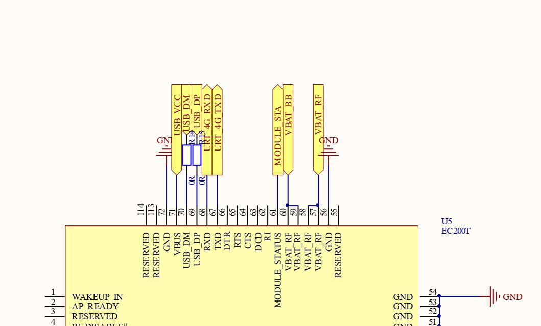
EC20 4G模块可以通过串口和USB去驱动,但是串口速度比较慢,所以通过USB驱动才能提高通信速率。
硬件连接:
STM32F407:

EC20模块:

部分参考代码:
/* USER CODE END Header */
/* Includes ------------------------------------------------------------------*/
#include "main.h"
#include "usb_host.h"
#include "usbh_def.h"
#include "usbh_cdc.h"
#include "string.h"

UART_HandleTypeDef huart1;

/* USER CODE BEGIN PV */

/* USER CODE END PV */

/* Private function prototypes -----------------------------------------------*/
void SystemClock_Config(void);
static void MX_GPIO_Init(void);
static void MX_USART1_UART_Init(void);
void MX_USB_HOST_Process(void);


unsigned char recData[100];
unsigned int recLen;

void delay_ums(unsigned int i)
{
	unsigned int cnt;
	while(i--)
	{
		cnt=33500;
		while(cnt--);
	}
}

 extern USBH_HandleTypeDef hUsbHostFS;
int main(void)
{
	unsigned int a;
	HAL_Init();
	SystemClock_Config();
	MX_GPIO_Init();
	MX_USART1_UART_Init();
	MX_USB_HOST_Init();
	MX_GPIO_Init();

	HAL_GPIO_WritePin(GPIOC, GPIO_PIN_0, GPIO_PIN_SET);

	delay_ums(1000);
	HAL_GPIO_WritePin(GPIOC, GPIO_PIN_0, GPIO_PIN_RESET);

  while (1)
  {
    /* USER CODE END WHILE */
    MX_USB_HOST_Process();
	delay_ums(1);
	  a++;
	  if(a>1000)
	  {
		  a=0;
		  USBH_CDC_Transmit(&hUsbHostFS, "ATrn", strlen("ATrn"));
	  }
    /* USER CODE BEGIN 3 */
  }
  /* USER CODE END 3 */
}

/**
  * @brief System Clock Configuration
  * @retval None
  */
void SystemClock_Config(void)
{
  RCC_OscInitTypeDef RCC_OscInitStruct = {0};
  RCC_ClkInitTypeDef RCC_ClkInitStruct = {0};

  /** Configure the main internal regulator output voltage
  */
  __HAL_RCC_PWR_CLK_ENABLE();
  __HAL_PWR_VOLTAGESCALING_CONFIG(PWR_REGULATOR_VOLTAGE_SCALE1);
  /** Initializes the RCC Oscillators according to the specified parameters
  * in the RCC_OscInitTypeDef structure.
  */
  RCC_OscInitStruct.OscillatorType = RCC_OSCILLATORTYPE_HSE;
  RCC_OscInitStruct.HSEState = RCC_HSE_ON;
  RCC_OscInitStruct.PLL.PLLState = RCC_PLL_ON;
  RCC_OscInitStruct.PLL.PLLSource = RCC_PLLSOURCE_HSE;
  RCC_OscInitStruct.PLL.PLLM = 4;
  RCC_OscInitStruct.PLL.PLLN = 168;
  RCC_OscInitStruct.PLL.PLLP = RCC_PLLP_DIV2;
  RCC_OscInitStruct.PLL.PLLQ = 7;
  if (HAL_RCC_OscConfig(&RCC_OscInitStruct) != HAL_OK)
  {
    Error_Handler();
  }
  /** Initializes the CPU, AHB and APB buses clocks
  */
  RCC_ClkInitStruct.ClockType = RCC_CLOCKTYPE_HCLK|RCC_CLOCKTYPE_SYSCLK
                              |RCC_CLOCKTYPE_PCLK1|RCC_CLOCKTYPE_PCLK2;
  RCC_ClkInitStruct.SYSCLKSource = RCC_SYSCLKSOURCE_PLLCLK;
  RCC_ClkInitStruct.AHBCLKDivider = RCC_SYSCLK_DIV1;
  RCC_ClkInitStruct.APB1CLKDivider = RCC_HCLK_DIV4;
  RCC_ClkInitStruct.APB2CLKDivider = RCC_HCLK_DIV2;

  if (HAL_RCC_ClockConfig(&RCC_ClkInitStruct, FLASH_LATENCY_5) != HAL_OK)
  {
    Error_Handler();
  }
}

/**
  * @brief USART1 Initialization Function
  * @param None
  * @retval None
  */
static void MX_USART1_UART_Init(void)
{

  /* USER CODE BEGIN USART1_Init 0 */

  /* USER CODE END USART1_Init 0 */

  /* USER CODE BEGIN USART1_Init 1 */

  /* USER CODE END USART1_Init 1 */
  huart1.Instance = USART1;
  huart1.Init.BaudRate = 115200;
  huart1.Init.WordLength = UART_WORDLENGTH_8B;
  huart1.Init.StopBits = UART_STOPBITS_1;
  huart1.Init.Parity = UART_PARITY_NONE;
  huart1.Init.Mode = UART_MODE_TX_RX;
  huart1.Init.HwFlowCtl = UART_HWCONTROL_NONE;
  huart1.Init.OverSampling = UART_OVERSAMPLING_16;
  if (HAL_UART_Init(&huart1) != HAL_OK)
  {
    Error_Handler();
  }
  /* USER CODE BEGIN USART1_Init 2 */

  /* USER CODE END USART1_Init 2 */

}

/**
  * @brief GPIO Initialization Function
  * @param None
  * @retval None
  */
static void MX_GPIO_Init(void)
{
  GPIO_InitTypeDef GPIO_InitStruct = {0};

	/* GPIO Ports Clock Enable */
	__HAL_RCC_GPIOH_CLK_ENABLE();
	__HAL_RCC_GPIOA_CLK_ENABLE();
	__HAL_RCC_GPIOC_CLK_ENABLE();
  /*Configure GPIO pin Output Level */


  /*Configure GPIO pin : PA15 */
  GPIO_InitStruct.Pin = GPIO_PIN_15;
  GPIO_InitStruct.Mode = GPIO_MODE_OUTPUT_PP;
  GPIO_InitStruct.Pull = GPIO_NOPULL;
  GPIO_InitStruct.Speed = GPIO_SPEED_FREQ_HIGH;
  HAL_GPIO_Init(GPIOA, &GPIO_InitStruct);
  HAL_GPIO_WritePin(GPIOA, GPIO_PIN_15, GPIO_PIN_SET);


  /*Configure GPIO pin : PA15 */
  GPIO_InitStruct.Pin = GPIO_PIN_0|GPIO_PIN_2;
  GPIO_InitStruct.Mode = GPIO_MODE_OUTPUT_PP;
  GPIO_InitStruct.Pull = GPIO_NOPULL;
  GPIO_InitStruct.Speed = GPIO_SPEED_FREQ_HIGH;
  HAL_GPIO_Init(GPIOC, &GPIO_InitStruct);
  HAL_GPIO_WritePin(GPIOC, GPIO_PIN_0|GPIO_PIN_2, GPIO_PIN_RESET);
}

/* USER CODE BEGIN 4 */

/* USER CODE END 4 */

/**
  * @brief  This function is executed in case of error occurrence.
  * @retval None
  */
void Error_Handler(void)
{
  /* USER CODE BEGIN Error_Handler_Debug */
  /* User can add his own implementation to report the HAL error return state */

  /* USER CODE END Error_Handler_Debug */
}

#ifdef  USE_FULL_ASSERT
/**
  * @brief  Reports the name of the source file and the source line number
  *         where the assert_param error has occurred.
  * @param  file: pointer to the source file name
  * @param  line: assert_param error line source number
  * @retval None
  */
void assert_failed(uint8_t *file, uint32_t line)
{
  /* USER CODE BEGIN 6 */
  /* User can add his own implementation to report the file name and line number,
     tex: printf("Wrong parameters value: file %s on line %drn", file, line) */
  /* USER CODE END 6 */
}
#endif /* USE_FULL_ASSERT */

/************************ (C) COPYRIGHT STMicroelectronics *****END OF FILE****/
void USBH_CDC_ReceiveCallback(USBH_HandleTypeDef *phost)
{
	recLen = USBH_CDC_GetLastReceivedDataSize(phost);

	HAL_UART_Transmit_IT(&huart1 ,(uint8_t*)recData,recLen);
	while(__HAL_UART_GET_FLAG(&huart1,UART_FLAG_TC)!=SET);		//等待发送结束

	memset(recData,0x00,sizeof(recData));
}
注意点:
完整MDK工程链接,点击下载
最后
以上就是老实冷风最近收集整理的关于STM32F407通过自带USB驱动EC20 4G模块-完整工程的全部内容,更多相关STM32F407通过自带USB驱动EC20内容请搜索靠谱客的其他文章。
本图文内容来源于网友提供,作为学习参考使用,或来自网络收集整理,版权属于原作者所有。


发表评论 取消回复