题目:根据状态转移图实现时序电路_牛客题霸_牛客网
解法一:
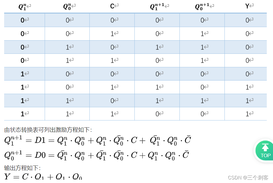
本题提供的是状态转换图,可采用状态机实现,也可采用列激励方程、输出方程,进而用D触发器和组合逻辑电路实现。本题解采用第二种方案实现。
由状态转换图可得出,电路共4个状态,所以使用2个寄存器来实现状态的寄存。两个寄存器的输出为Q1和Q0,两个寄存器的输入为D1和D0。
`timescale 1ns/1ns

module seq_circuit(
   input                C   ,
   input                clk ,
   input                rst_n,

   output   wire        Y
);
    reg q1;
    reg q0;
    always@(posedge clk or negedge rst_n)begin
        if(!rst_n)
            q1 <= 1'b0;
        else
            q1 <= (q1 & (q0 | C)) | (~q1 & q0 & ~C);
    end
    always@(posedge clk or negedge rst_n)begin
        if(!rst_n)
            q0 <= 1'b0;
        else
            q0 <= (~q1 & (q0 | C)) | (q1 & q0 & ~C);
    end
    assign Y = (C & q1) | (q1 & q0);
endmodule
解法二:三段式状态机
第一段,时序逻辑实现状态转移
第二段,组合逻辑实现状态跳转
第三段,组合逻辑实现状态内的赋值
第一个always时序初态和次态,第二个always组合逻辑描述状态转移,第三个always组合逻辑描述输出。输出可以不合并,编译器会帮你优化的。
注意:第二段我刚开始使用的时序逻辑输出,部分代码如下:
always@(posedge clk or negedge rst_n)begin  //括号里改为*就好了
        if(!rst_n)
            curr_state <= 2'b00;
发现答案不通过,波形如下:
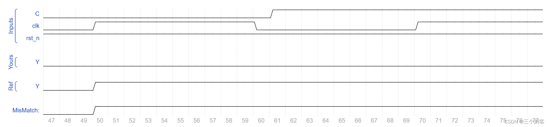
明显看出,我的Y比参考答案延后了一个时钟周期,因为时序逻辑会延后一个时钟周期,根据波形逆推,所以采用了组合逻辑,代码如下:
`timescale 1ns/1ns

module seq_circuit(
   input                C   ,
   input                clk ,
   input                rst_n,

   output   wire        Y
);
    reg Y1;
    reg [1:0] curr_state;
    reg [1:0] next_state;
    // 当前状态切换,时序逻辑
    always@(posedge clk or negedge rst_n)begin
        if(!rst_n)
            curr_state <= 2'b00;
        else
            curr_state <= next_state;
    end
    // 下个状态更新,组合逻辑
    always@(*)
            case(curr_state)
                2'b00: begin
                if(C==1)
                    next_state <= 2'b01;
                else
                    next_state <= 2'b00;

                end
                2'b01: begin
                if(C==1)
                    next_state <= 2'b01;
                else
                    next_state <= 2'b11;

                end
                2'b10: begin
                if(C==1)
                    next_state <= 2'b10;
                else
                    next_state <= 2'b00;

                end
                2'b11: begin
                if(C==1)
                    next_state <= 2'b10;
                else
                    next_state <= 2'b11;

                end
                default: next_state <= 2'b00;
            endcase
    // 输出,组合逻辑
    always@(*)begin
        case(curr_state)
            2'b11: Y1 = 1;
            2'b10: Y1 = C ? 1 : 0;
            2'b00: Y1 = 0;
            2'b01: Y1 = 0;
        endcase
    end
    assign Y = Y1;
endmodule
解法三:
这里有别于日常所见的FSM,根据状态转移图,输出Y的表达式受当前状态以及同一时刻次态的状态影响
`timescale 1ns/1ns

module seq_circuit(
   input                C   ,
   input                clk ,
   input                rst_n,

   output   wire        Y
);
    reg [1:0] curr_state;
    reg [1:0] next_state;
    always@(posedge clk or negedge rst_n)begin
        if(!rst_n)
            curr_state <= 2'b00;
        else
            curr_state <= next_state;
    end
    always@(*)begin
            case(curr_state)
                2'b00: begin
                if(C==1)
                    next_state <= 2'b01;
                else if(C==0)
                    next_state <= 2'b00;
                else
                    next_state <= next_state;
                end
                2'b01: begin
                if(C==1)
                    next_state <= 2'b01;
                else if(C==0)
                    next_state <= 2'b11;
                else
                    next_state <= next_state;
                end
                2'b10: begin
                if(C==1)
                    next_state <= 2'b10;
                else if(C==0)
                    next_state <= 2'b00;
                else
                    next_state <= next_state;
                end
                2'b11: begin
                if(C==1)
                    next_state <= 2'b10;
                else if(C==0)
                    next_state <= 2'b11;
                else
                    next_state <= next_state;
                end
                default: next_state <= 2'b00;
            endcase
    end
    assign Y = (curr_state == 2'b10 && C==1) | (curr_state == 2'b11);
    //这里有别于日常所见的FSM,根据状态转移图,输出Y的表达式受当前状态以及同一时刻次态的状态影响
endmodule
最后
以上就是甜甜蛋挞最近收集整理的关于牛客刷题<22>根据状态转移图实现时序电路的全部内容,更多相关牛客刷题<22>根据状态转移图实现时序电路内容请搜索靠谱客的其他文章。
本图文内容来源于网友提供,作为学习参考使用,或来自网络收集整理,版权属于原作者所有。


发表评论 取消回复