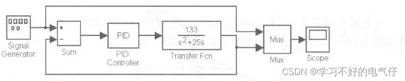
以二阶线性传递函数 。为被控对象,进行模拟PID控制。在信号发生器中选择正弦信号,仿真时取
 ,
, ,
, ,输入指令为
 ,其中A=1.0,F=0.20Hz。采用ODE45迭代方法,仿真时间为10s。
PID控制器由Simulink下的工具箱提供。
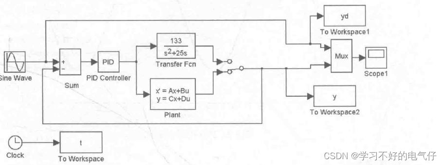
仿真图:
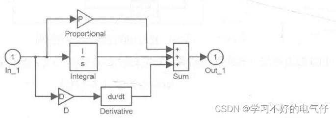
上述PID控制器采用Simulink封装的形式,内部结构如下:
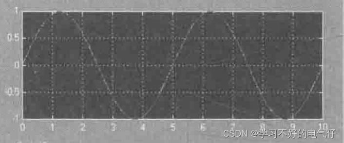
正弦响应结果如图所示:
在上述仿真的基础上,将仿真结果输出到工作空间中,利用M语言作图,仿真结果如图:
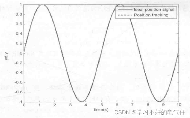
仿真图:
作图程序:chap1_2plot.m
close all;
plot(t,yd(:,1),‘r',1,y(:,1),‘k:',linewidth', 2);
xlabel('time(s)’);
ylabel('yd,y');
legend('Ideal position signal','Position tracking');
最后
以上就是明亮火车最近收集整理的关于连续系统PID的Simulink仿真-1的全部内容,更多相关连续系统PID内容请搜索靠谱客的其他文章。
本图文内容来源于网友提供,作为学习参考使用,或来自网络收集整理,版权属于原作者所有。


发表评论 取消回复