文章目录
- 一、课程设计内容
- 二、实验方案分析与设计
- 1.功能要求
- 2.各个模块描述
- 三、具体实现过程描述
- 1、小时计时
- 2、分计时
- 3、秒计时
- 4、闹钟小时计时
- 5、闹钟分计时
- 6、闹钟比较模块
- 7、控制器模块(设置状态转换)
- 8、控制显示模块(显示时间以及校时,校分,秒清零,设置闹钟)
- 9、分频器模块
- 10、报时模块
- 11、动态扫描显示模块
- 12、二选一模块
- 13、倒计时模块
- 14、倒计时开关模块
- 四、结论实现效果
一、课程设计内容
1、能进行正常的时、分、秒计时,分别用6个七段数码管动态扫描显示时、分、秒。时时-分分-秒秒
2、利用按键开关快速调整时间(校准):时、分
3、通过按键开关设定闹铃时间,到了设定时间发出闹铃提示音,提示音长度为1分钟
4、通过按键开关设定倒计时的时间,通过开关启动/暂停倒计时,倒计时为0时发出提示音,提示音长度为1分钟
5、整点报时:在59分50、52、54、56、58秒时按500Hz频率报时,在59分60秒时用1KHz的频率作最后一声整点报时
6、其他功能自由发挥:秒表、多个闹钟、多个时区、功能选择控制等
二、实验方案分析与设计
1.功能要求

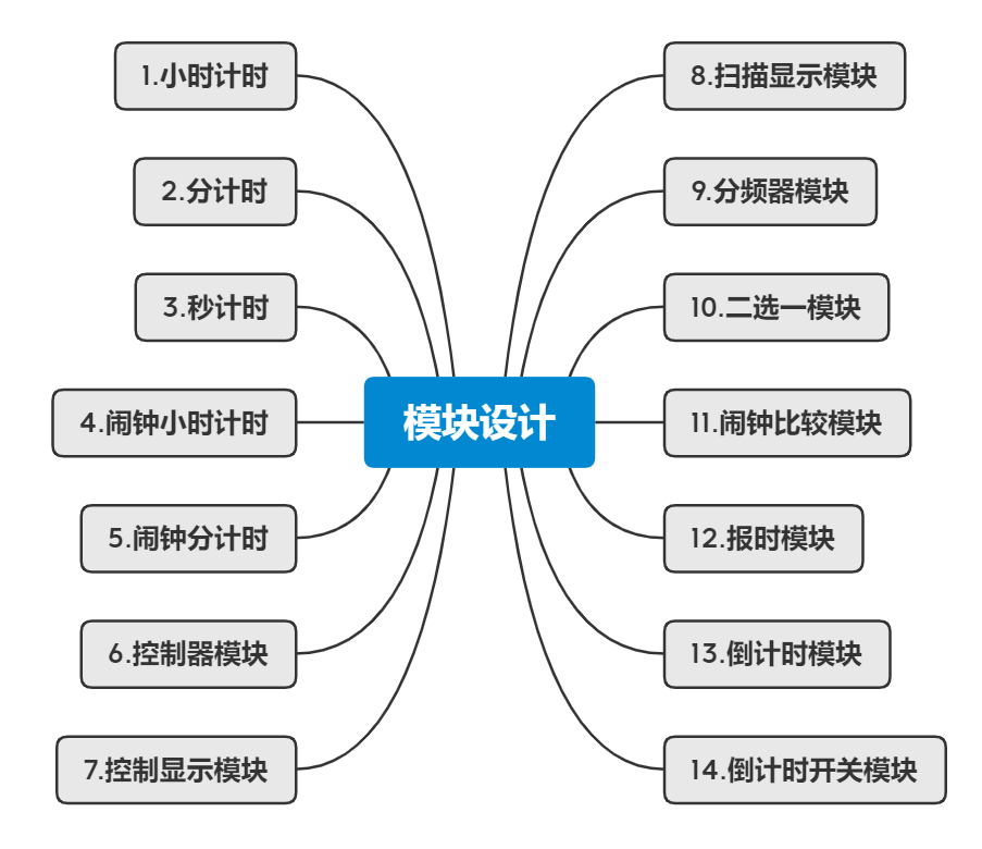
根据功能要求的描述,我将该实验一共分为十四个模块进行设计,各个模块使用vhdl语言设计,顶层使用电路图的层次化设计。分别有以下模块:小时计时,分计时,秒计时,闹钟小时计时,闹钟分计时,控制器模块,控制显示模块,扫描显示模块,分频器模块,二选一模块,闹钟比较模块、报时模块,倒计时模块,倒计时开关模块。
各个模块设计的思维导图:
2.各个模块描述
1、小时计时:24进制计数器。正常显示时间时,每当分中产生的进位信号到达一次时自增一次,当时计数器每次计数到23时,在下一个分进位信号到来时,时变为00。当在校时时,接入1hz的时钟频率,每次时钟上升沿到来时自增一次,当时计数器计数到23时,在下一个时钟上升沿到来时,时直接变为00。
2、分计时:60进制计数器。正常显示时间时,每当秒中产生的进位信号到达一次分自增一次,当分计数器每次计数到59时,在下一个秒进位信号到来时,分变为00,并且产生进位。当在校分时,接入1hz的时钟频率,每次时钟上升沿到来分自增一次,当分计数器计数到59时,在下一个时钟上升沿到来时,分直接变为00,并不产生进位。
3、秒计时:60进制计数器。接入1hz的时钟频率,正常显示时间的状态下,每次时钟上升沿到来后秒加一,当秒计数器每次计数到59时,在下一个时钟边沿到来时,秒变为00,产生进位。当在秒清零时,秒直接变为00不产生进位。
4、闹钟小时计时:24进制计数器。设置闹钟的小时时,接入1hz的时钟频率,每次时钟上升沿到来时自增一次,当时计数器计数到23时,在下一个时钟上升沿到来时,时直接变为00。
5、闹钟分计时:60进制计数器。设置闹钟的分钟时,接入1hz的时钟频率,每次时钟上升沿到来分自增一次,当分计数器计数到59时,在下一个时钟上升沿到来时,分直接变为00,并不产生进位。
6、控制器模块:控制计时时间状态,调计时的时、分、秒状态,调闹铃的时、分的状态这六个状态之间的转换。在enset打开的条件下可以,通过开关k的开闭控制状态转换,第一次打开开关k,状态从正常计时时间状态转换到校时,再次关闭开关状态将变换为校分,接下来秒清零,调节闹钟的时,调节闹钟的分,正常计时,如此循环。不论什么状态,当打开reset时,都会使当前状态变为正常计时的状态。
7、控制显示模块:控制LED显示的是正常显示时间还是校时、校分、秒清零、设置闹钟时、分的显示,当在校时、校分、秒清零、设置闹钟时、分的显示中,被设置的数字以2hz的频率闪烁,并以1hz的频率自增,当打开set键时停止自增。
8、扫描显示模块:以八个LED数码管扫描显示对应的数字,每一次时钟脉冲到来显示一个,八个为一组循环显示,当频率较大时因为人的视觉停留效果,使得显示表现为同时显示的效果。
9、分频器模块:输入一个1khz的时钟频率,对1khz的时钟脉冲每两个脉冲输出一个脉冲如此得到500hz的频率,同理得到2hz和1hz的频率。
10、二选一模块:通过显示正常计时时间和显示闹钟时间,选择合适的信号作为调整对应时间的控制条件。当在正常计时时用秒用1hz的时钟脉冲,时、分用进位信号控制,在校时、校分、设置闹钟时、分时各个都用1hz的时钟信号作为控制信号。
11、闹钟比较模块:若闹钟的时分与目前的时间的时分相同,则输出结果为1,否则输出为0.
12、报时模块:当控制声音的开关打开时,扬声器在每一小时59分的51、53、57秒发出频率为500Hz的低音,在59分钟的第59秒发频率为1000Hz的高音,结束时为整点,实现整点报时功能。当闹钟比较模块输出为1时,扬声器发出频率为1000Hz的高音,持续时间为60秒。
13、倒计时模块:设置倒计时的时间,时间会按秒钟每次减少1秒,直到归零。
14、倒计时开关模块:当控制声音的开关打开时,倒计时时间到了以后,会有1分钟的提示音。
三、具体实现过程描述
1、小时计时
library ieee;
use ieee.std_logic_1164.all;
use ieee.std_logic_unsigned.all;
use ieee.std_logic_arith;
entity cnt24 is
port(sld0:buffer std_logic_vector(3 downto 0);
	sld1:buffer std_logic_vector(7 downto 4);
	clk :in std_logic);
end cnt24;
architecture rtl of cnt24 is
signal s:std_logic_vector(7 downto 0);
begin
process(clk)
begin
	s<=sld1&sld0;
if (clk'event and clk='1') then
	if s="00100011"then
		sld1<="0000";
		sld0<="0000";
	elsif sld0="1001" then
		sld0<="0000";
		sld1<=sld1+1;
	else sld0<=sld0+1;
	end if;
end if;
end process;
end rtl;
模块图如下: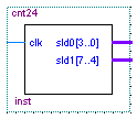
2、分计时
library ieee;
use ieee.std_logic_1164.all;
use ieee.std_logic_unsigned.all;
use ieee.std_logic_arith;
entity cnt60 is
port(sld0:buffer std_logic_vector(3 downto 0);
sld1:buffer std_logic_vector(7 downto 4);
co:  out std_logic;
clk :in std_logic);
end cnt60;
architecture rtl of cnt60 is
begin
process(clk)
begin
if (clk'event and clk='1') then
if (sld1="0101"and sld0="1001")then
sld1<="0000"; sld0<="0000";co<='1';
elsif sld0="1001" then
sld0<="0000";
sld1<=sld1+1;co<='0';
else sld0<=sld0+1;co<='0';
end if;
end if;
end process;
end rtl;
模块图如下: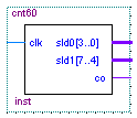
3、秒计时
library ieee;
use ieee.std_logic_1164.all;
use ieee.std_logic_unsigned.all;
use ieee.std_logic_arith;
entity cnts60 is
port(sld0:buffer std_logic_vector(3 downto 0);  --小时个位
	sld1:buffer std_logic_vector(7 downto 4);  --小时十位
	co:  out std_logic;
	rest:in std_logic;
	clk :in std_logic);
end cnts60;
architecture rtl of cnts60 is
begin
process(clk,rest)
begin
if rest='1' then sld1<="0000"; sld0<="0000";
elsif (clk'event and clk='1') then
	if (sld1="0101"and sld0="1001")then    --当sld1=5,sld0=9时
		sld1<="0000"; sld0<="0000";co<='1';--全清零,co输出“1”
	elsif sld0="1001" then
		sld0<="0000";
		sld1<=sld1+1;co<='0';        -- sld1自加“1”
	else sld0<=sld0+1;co<='0';
	end if;
end if;
end process;
end rtl;
模块图如下: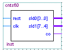
4、闹钟小时计时
library ieee;
use ieee.std_logic_1164.all;
use ieee.std_logic_unsigned.all;
use ieee.std_logic_arith;
entity cnth24b is
port(sld0:buffer std_logic_vector(3 downto 0);
	sld1:buffer std_logic_vector(7 downto 4);
	en:in std_logic;
	clk :in std_logic);
end cnth24b;
architecture rtl of cnth24b is
signal s:std_logic_vector(7 downto 0);
begin
process(clk,en,sld1,sld0)
begin
	s<=sld1&sld0;
if (clk'event and clk='1') then
	if en='1' then
		if s="00100011"then
			sld1<="0000";
			sld0<="0000";
		elsif sld0="1001" then
			sld0<="0000";
			sld1<=sld1+1;
		else sld0<=sld0+1;
		end if;
	end if;
end if;
end process;
end rtl;
5、闹钟分计时
library ieee;
use ieee.std_logic_1164.all;
use ieee.std_logic_unsigned.all;
use ieee.std_logic_arith;
entity cntm60b is
port(sld0:buffer std_logic_vector(3 downto 0);
	sld1:buffer std_logic_vector(7 downto 4);
	en:in std_logic;
	clk :in std_logic);
end cntm60b;
architecture rtl of cntm60b is
begin
process(clk)
begin
if (clk'event and clk='1') then
	if en='1' then
		if (sld1="0101"and sld0="1001")then
			sld1<="0000"; sld0<="0000";
		elsif sld0="1001" then
			sld0<="0000";
			sld1<=sld1+1;
		else sld0<=sld0+1;
		end if;
	end if;
end if;
end process;
end rtl;
6、闹钟比较模块
library ieee;
use ieee.std_logic_1164.all;
entity comp is
port(th1,tm1:in std_logic_vector(7 downto 4);
	th0,tm0:in std_logic_vector(3 downto 0);
	bh1,bm1:in std_logic_vector(7 downto 4);
	bh0,bm0:in std_logic_vector(3 downto 0);
compout:out std_logic);
end comp;
architecture rtl of comp is
begin
process(th1,tm1,bh1,bm1,th0,tm0,bh0,bm0)
begin
if( th1=bh1 and tm1=bm1  and th0=bh0 and tm0=bm0 ) then
	compout<='1';--当正常计数时间与闹钟定时时间相等时compout输出1
else compout<='0';
end if;
end process;
end rtl;
7、控制器模块(设置状态转换)
–输入端口enset,k,set键来控制6个状态,这六个状态分别是
–显示计时时间状态,调计时的时、分、秒状态,调闹铃的时、分的状态,reset键是复位键,用来回到显示计时时间的状态。
library ieee;
use ieee.std_logic_1164.all;
entity contl is
port(clk,enset,k,set,reset:in std_logic;
cth,ctm,cts,cbh,cbm,flashh,flashm,flashs,sel_show:out std_logic);
end contl;
architecture rtl of contl is
type stats is (s0,s1,s2,s3,s4,s5);            --定义6个状态
signal current_state,next_state:stats:=s0;
begin
process(clk,reset)
begin
if reset='1' then
	current_state<=s0;
elsif clk'event and clk='1' then
	if reset='0' then
		current_state<=next_state;
	end if;
end if;
end process;
process(current_state,enset,k,set)
begin
case current_state is
	when s0=>cth<='0';ctm<='0';cts<='0';cbh<='0';cbm<='0';
		flashh<='0';flashm<='0';flashs<='0';sel_show<='0';--sel_show为'0'时显示正常时间,为1时显示闹钟时间
		if (enset='1' and k='1')then    --若enset和k为“1”,
		next_state<=s1;                --由s0态转到s1态
	else next_state<=s0;
	end if;
	when s1=>ctm<='0';cts<='0';cbh<='0';cbm<='0';
		flashh<='1';flashm<='0';flashs<='0';sel_show<='0';
	if set='1' then cth<='1';    --若set为“1”,cth输出“1”
	else cth<='0';                --进入调小时状态。
	end if;
	if (enset='1' and k='0')then  --若enest为“1”,k为“0”,
		next_state<=s2;            --由s1态转到s2态
	else next_state<=s1;
	end if;
	when s2=>cth<='0';cts<='0';cbh<='0';cbm<='0';
		flashh<='0';flashm<='1';flashs<='0';sel_show<='0';---
	if set='1' then ctm<='1';
	else ctm<='0';
	end if;
	if(enset='1' and k='1')then
		next_state<=s3;
	else next_state<=s2;
	end if;
	when s3=>cth<='0';ctm<='0';cbh<='0';cbm<='0';
		flashh<='0';flashm<='0';flashs<='1';sel_show<='0';
	if set='1' then cts<='1';
	else cts<='0';
	end if;
	if (enset='1' and k='0')then
		next_state<=s4;
	else next_state<=s3;
	end if;
	when s4=>cth<='0';ctm<='0';cts<='0';cbm<='0';
		flashh<='1';flashm<='0';flashs<='0';sel_show<='1';
	if set='1' then cbh<='1';
	else cbh<='0';
	end if;
	if(enset='1' and k='1')then
		next_state<=s5;
	else next_state<=s4;
	end if;
	when s5=>cth<='0';ctm<='0';cts<='0';cbh<='0';
		flashh<='0';flashm<='1';flashs<='0';sel_show<='1';
	if set='1' then cbm<='1';
	else cbm<='0';
	end if;
	if(enset='1' and k='0')then
		next_state<=s0;
	else next_state<=s5;
	end if;
end case;
end process;
end rtl;
8、控制显示模块(显示时间以及校时,校分,秒清零,设置闹钟)
--该模块实现了数码管既可以显示正常时间,又可以显示闹钟时间的功能;调时,定时闪烁功能也在此模块中真正实现。
library ieee;
use ieee.std_logic_1164.all;
entity show_con is
port(th1,tm1,ts1:in std_logic_vector(7 downto 4);
	th0,tm0,ts0:in std_logic_vector(3 downto 0);
	bh1,bm1:in std_logic_vector(7 downto 4);
	bh0,bm0:in std_logic_vector(3 downto 0);
	sec1,min1,h1: out std_logic_vector(7 downto 4);
	sec0,min0,h0: out std_logic_vector(3 downto 0);
	q2Hz,flashs,flashh,flashm,sel_show:in std_logic);
end show_con;
architecture rtl of show_con is
begin
process(th1,tm1,ts1,th0,tm0,ts0,bh1,bm1,bh0,bm0,q2Hz,flashs,flashh,flashm,sel_show)
begin
if sel_show='0'then
	if ( flashh='1'and q2Hz='1')then
		h1<="1111";h0<="1111";  --显示小时数码管以2Hz闪烁
		min1<=tm1;min0<=tm0;
		sec1<=ts1;sec0<=ts0;
	elsif (flashm='1'and q2Hz='1')then
		h1<=th1;h0<=th0;
		min1<="1111";min0<="1111";
		sec1<=ts1;sec0<=ts0;
	elsif (flashs='1'and q2Hz='1')then
		h1<=th1;h0<=th0;
		min1<=tm1;min0<=tm0;
		sec1<="1111";sec0<="1111";
	else
		h1<=th1;h0<=th0;
		min1<=tm1;min0<=tm0;
		sec1<=ts1;sec0<=ts0;
	end if;
elsif sel_show='1'then--若sel_show为“1”,数码管显示闹钟时间
	if(flashh='1' and q2Hz='1')then
		h1<="1111";h0<="1111";
		min1<=bm1;min0<=bm0;
		sec1<="0000";sec0<="0000";
	elsif ( flashm='1' and q2Hz='1')then
		h1<=bh1;h0<=bh0;
		min1<="1111";min0<="1111";
		sec1<="0000";sec0<="0000";
	else
		h1<=bh1;h0<=bh0;
		min1<=bm1;min0<=bm0;
		sec1<="0000";sec0<="0000";
	end if ;
end if;
end process;
end rtl;
9、分频器模块
---输入一个频率为1khz的CLK,利用计数器分出500Hz的q500Hz,2Hz的q2Hz和1Hz的q1Hz。
LIBRARY ieee;
USE ieee.std_logic_1164.all;
use ieee.std_logic_unsigned.all;
ENTITY fdiv IS
PORT  (clk: IN STD_LOGIC ;                --输入时钟信号(1khz)
	q500Hz: BUFFER STD_LOGIC;
	q2Hz: BUFFER STD_LOGIC;
	q1Hz: OUT STD_LOGIC);
END fdiv ;
ARCHITECTURE bhv OF fdiv IS
BEGIN

P500HZ:PROCESS(clk)              --1KHz作为输入信号,分出q500Hz
VARIABLE cout:INTEGER:=0;
BEGIN
IF clk'EVENT AND clk='1' THEN
	cout:=cout+1;
	IF cout=1 THEN q500Hz<='0';          --二分频
	ELSIF cout=2 THEN cout:=0;q500Hz<='1';
	END IF;
END IF;
END PROCESS;
P2HZ:PROCESS(q500Hz)
VARIABLE cout:INTEGER:=0;
BEGIN
IF q500Hz'EVENT AND q500Hz='1' THEN
	cout:=cout+1;
	IF cout<=125 THEN q2Hz<='0';
	ELSIF cout<250 THEN q2Hz<='1';
	ELSE cout:=0;
	END IF;
END IF;
END PROCESS;
P1HZ:PROCESS(q2Hz)
VARIABLE cout:INTEGER:=0;
BEGIN
IF q2Hz'EVENT AND q2Hz='1' THEN
	cout:=cout+1;
	IF cout=1 THEN q1Hz<='0';
	ELSIF cout=2 THEN cout:=0;q1Hz<='1';
	END IF;
END IF;
END PROCESS;
END bhv;
10、报时模块
--该模块既实现了整点报时的功能,又实现了闹铃的功能,蜂鸣器通过所选频率的不同,而发出不同的声音。
library ieee;
use ieee.std_logic_1164.all;
use ieee.std_logic_unsigned.all;
entity bel is
port(tm1,ts1:in std_logic_vector(7 downto 4);
tm0,ts0:in std_logic_vector(3 downto 0);
compout,q1KHz,q500Hz,openbel:in std_logic;
bell:out std_logic);
end bel;
architecture rtl of bel is
signal t:std_logic_vector(7 downto 0);
begin
process(compout,q500Hz,q1KHz,openbel,tm1,tm0,ts1,ts0)
begin
if (openbel ='0' ) then
bell<='0';
end if;
if (openbel ='1' ) then
	if (compout='1') then        -- compout=1,闹铃响
		bell<=q1KHz;              --bell输出1KHz
	elsif (tm1="0101" and tm0="1001"and ts1="0101")then----整点报时
		case ts0 is
		when"0001"=>bell<=q500Hz;
		when"0011"=>bell<=q500Hz;
		when"0101"=>bell<=q500Hz;
		when"0111"=>bell<=q500Hz;  --bell输出500Hz
		when"1001"=>bell<=q1KHz;    --bell输出1KHz
		when others=>bell<='0';
		end case;
	else bell<='0';
	end if;
end if;
end process;
end rtl;
11、动态扫描显示模块
--由6组输入信号和7个数据输出信号和8个位选通信号来实现数码管的驱动和信号扫描,进而实现了时钟时,分,秒的动态显示。
library ieee;
use ieee.std_logic_1164.all;
use ieee.std_logic_unsigned.all;
entity SCAN_LED is
port(clk1:in std_logic;
h0:in std_logic_vector(3 downto 0);
h1:in std_logic_vector(7 downto 4);
min0:in std_logic_vector(3 downto 0);
min1:in std_logic_vector(7 downto 4);
sec0:in std_logic_vector(3 downto 0);
sec1:in std_logic_vector(7 downto 4);
ledag:out std_logic_vector(6 downto 0);
se:out std_logic_vector(2 downto 0));
end;
architecture one of SCAN_LED is
signal cnt6:std_logic_vector(2 downto 0);
signal  a: std_logic_vector(3 downto 0) ;
begin
p1:process(clk1)
begin
if clk1'event and clk1 ='1' then
cnt6<=cnt6+1;
end if;
se<=cnt6;
end process p1;
p2:process(cnt6,h1,h0,min1,min0,sec1,sec0)
begin
case cnt6 is                   --控制数码管位选
		when "111"=>a<=sec0;---表示第八个位置的显示为
      when "110"=>a<=sec1;
      when "101"=>a<="1010";----当sel1为10的时候七段码中g段发光(第三和第六个位置为'-')
      when "100"=>a<=min0;
      when "011"=>a<=min1;
      when "010"=>a<="1010";
      when "001"=>a<=h0;
      when "000"=>a<=h1;
      when others=>a<="XXXX";
end case;

end  process p2;
p3:process(a)
begin
case a is                       --控制数码管段选
when  "0000"=>ledag<="0111111";
when  "0001"=>ledag<="0000110";
when  "0010"=>ledag<="1011011";
when  "0011"=>ledag<="1001111";
when  "0100"=>ledag<="1100110";
when  "0101"=>ledag<="1101101";
when  "0110"=>ledag<="1111101";
when  "0111"=>ledag<="0000111";
when  "1000"=>ledag<="1111111";
when  "1001"=>ledag<="1101111";
when  "1010"=>ledag<="1000000";
when others=>ledag<="0000000";
end case;
end process p3;
end;
12、二选一模块
ENTITY mux21a IS
PORT(a,b,s:IN BIT;
y:OUT BIT);
END ENTITY mux21a;
ARCHITECTURE one OF mux21a IS
BEGIN
PROCESS(a,b,s)
BEGIN
IF s='0' THEN
y<=a;ELSE          --若s=0,y输出a,反之输出b。
y<=b;
END IF;
END PROCESS;
END ARCHITECTURE one;
13、倒计时模块
--设置倒计时时间,调频率
library ieee;
use ieee.std_logic_1164.all;
use ieee.std_logic_unsigned.all;
use ieee.std_logic_arith;
entity daojishi is
    port(sld0:buffer std_logic_vector(3 downto 0);
         sld1:buffer std_logic_vector(7 downto 4);
           en:in std_logic;
         clk :in std_logic);
end daojishi;
architecture rtl of daojishi is
  begin
      process(clk)
    begin
     if (clk'event and clk='1') then
      if en='1' then
       if (sld1="1001"and sld0="1001")then
            sld1<="0000"; sld0<="0000";
           elsif sld0="1001" then
                 sld0<="0000";
                 sld1<=sld1+1;
              else sld0<=sld0+1;
       end if;
      end if;
     end if;
    end process;
end rtl;
14、倒计时开关模块
--开关控制倒计时进度
library ieee;
use ieee.std_logic_1164.all;
use ieee.std_logic_unsigned.all;
use ieee.std_logic_arith;
entity bel1 is
    port(sld0:in std_logic_vector(3 downto 0);
         sld1:in std_logic_vector(7 downto 4);
			clk:in std_logic;
			en:in std_logic;
           compout:out std_logic);
end bel1;
architecture rtl of bel1 is
  begin
      process(clk,en,sld1,sld0)
		variable sld_1:std_logic_vector(7 downto 4);
		variable sld_0:std_logic_vector(3 downto 0);
		begin
		sld_0:=sld0;
		sld_1:=sld1;
if(en='1') then
   if (clk'event and clk='1') then
	  while(sld_1/="0000" and sld_0/="0000")loop
           if sld_0="0000" then
            sld_0:="1001";
            sld_1:=sld_1-1;
              else sld_0:=sld_0-1;
				  end if;
				  end loop;
		if (sld_1="0000"and sld_0="0000")then
            compout<='1';
      end if;
		end if;
		else compout<='0';
end if;
    end process;
end rtl;
顶层电路图如下: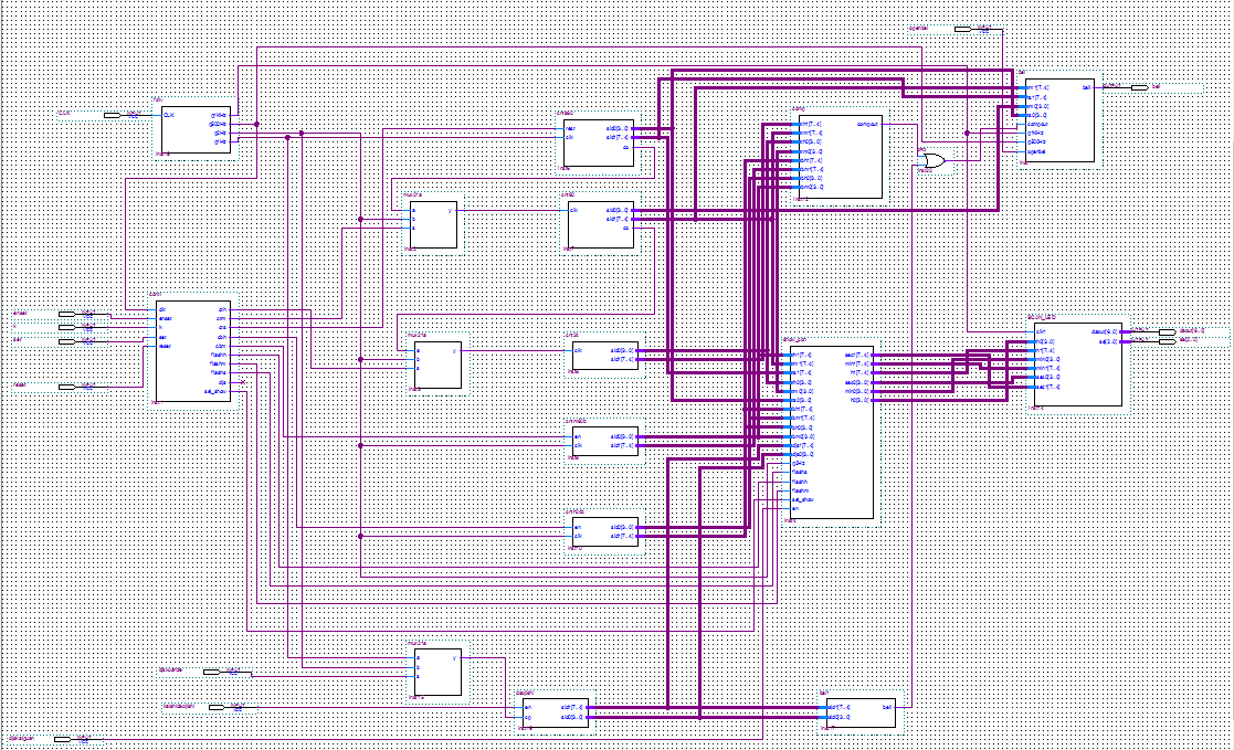
四、结论实现效果
用五个开关,以及一个1khz的时钟脉冲控制。
(1)reset开关为复位键,当打开该开关时显示正常计时时间。
(2)Openbel控制声音的开关,打开时有声音,关闭时没有声音。
(3)Enset控制是否可以进行状态转换,打开时可以转换状态,关闭时不可以。
(4)K控制状态之间的转换,在enset打开并且reset键关闭的条件下,每开一次或者关一次开关改变一次状态。
(5)Set键控制校对时间设置闹钟时对应的数字是否变化。打开时暂停改变,关闭时继续依时钟频率改变。
(6)clk为时钟频率,接入1khz的频率。
1 功能1——正常显示时分秒的效果
成功编译并运行,打开了K1键后,该功能便得以实现。数码管便显示出时时—分分—秒秒。
2 功能2——利用按键快速校时
关闭K1,打开K3,调整K4,打开K5便可实现对时、分、秒进行校时。调整到秒的时候,再调整K5,可以对秒进行清零操作。
3 功能3——设置闹钟功能
关闭K1,打开K3,调整K4到第四次,打开K5,便可以设置闹钟时间。再次调整K4便可以从时到分,秒。打开K2,到了闹铃规定的时间后,便会响铃一分钟。
4 功能4——设置倒计时报时功能
同功能3的实现和操作,倒计时到0后,便会响铃一分钟。
5 功能5——设置整点报时功能并能发出不同频率的声音
打开K1,打开K2,当时间到了每个小时的59分,50秒时,在50、52、54、6、58秒时会按500Hz频率报时,在59分60秒时会用1KHz的频率作最后一声整点报时。
最后
以上就是玩命眼睛最近收集整理的关于多功能数字时钟(VHDL)一、课程设计内容二、实验方案分析与设计三、具体实现过程描述四、结论实现效果的全部内容,更多相关多功能数字时钟(VHDL)一、课程设计内容二、实验方案分析与设计三、具体实现过程描述四、结论实现效果内容请搜索靠谱客的其他文章。


发表评论 取消回复