编写RTL代码
设计文件如下:
add.v
module adder(
input clk,
input wire [31:0] a,
input wire [31:0] b,
output reg [31:0] c
);

always@(posedge clk)
    c<=a+b;

endmodule
sub.v
module suber(
input wire clk,
input wire [31:0]  a,
input wire [31:0]  b,
output reg [31:0] c
);
always@(posedge clk)
    c<=a-b;
endmodule
顶层alu.v
module alu (
input wire clk,
input wire mode,
input wire [31:0] a,
input wire [31:0] b,
output reg [31:0] out
);

wire [31:0] c1;
wire [31:0] c2;

assign out=(mode==1)?c1:c2;             //mode==1,add,mode==0,sub

adder U1(
.clk(clk),
.a(a),
.b(b),
.c(c1)
);

suber U2(
.clk(clk),
.a(a),
.b(b),
.c(c2)
);

endmodule
testbench
module test;

reg clk;
reg [31:0] a;
reg [31:0] b;
wire [31:0] out;
reg mode;
//
initial begin
    clk=0;
    forever begin
        #5 clk=~clk;
    end
end
//
always@(posedge clk)
    mode<=$random%2;

always@(posedge clk)
begin
    a<=$random%128+128;
    b<=$random%128+128;
end

initial
begin
    #1000
    $stop;
end

alu U(.clk(clk),
      .mode(mode),
      .a(a),
      .b(b),
      .out(out));

initial begin
   $fsdbDumpfile("./alu.fsdb");
   $fsdbDumpvars(0);
end

endmodule
其中,代码块
initial begin
   $fsdbDumpfile("./alu.fsdb");
   $fsdbDumpvars(0);
end
是必须的,建议放在一个单独的initial块
VCS编译
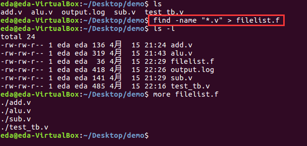
首先生成filelist文件,该文件包含rtl设计的所有.v文件的路径,我们通过如下命令生成:
然后使用vcs编译
vcs -full64 -f filelist.f -timescale=1ns/1ns -sverilog -debug_access -kdb -lca -R -l ./output.log
vcs的一些常用参数列举如下表
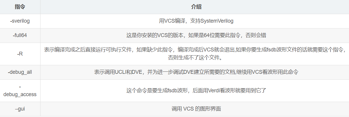
上述指令中,-l ./output.log表示生成log文件的名字是output.log并保存在当前文件夹;-sverilog选项开启SystemVerilog支持;添加-kdb选项支持输出KDB格式的数据,用于与Verdi在交互模式交换数据,而KDB格式属于"Limited Customer Availability"特性,必须通过-lca选项开启;-f filelist.f是从你的filelist下开始编译;vcs -full64一定要加,-full64这是版本号,不加很可能会报错;-timescale=1ns/1ps是编译的时间精度,也需要加上,并且和Testbench应该要保持一致。
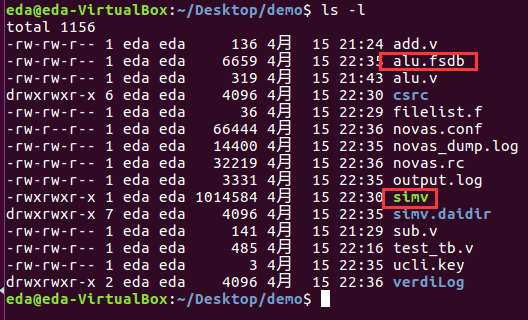
编译成功后,会得到这两个文件
Verdi查看波形
输入如下命令:
verdi -sv -f -Uart_rtl.f -ssf alu.fsdb
该指令的意思就是同时打开filelist.f这个list里面的文件和仿真生成的波形fsdb文件。
打开后界面如下所示
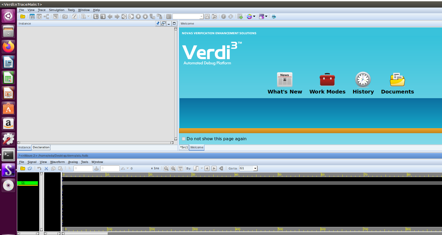
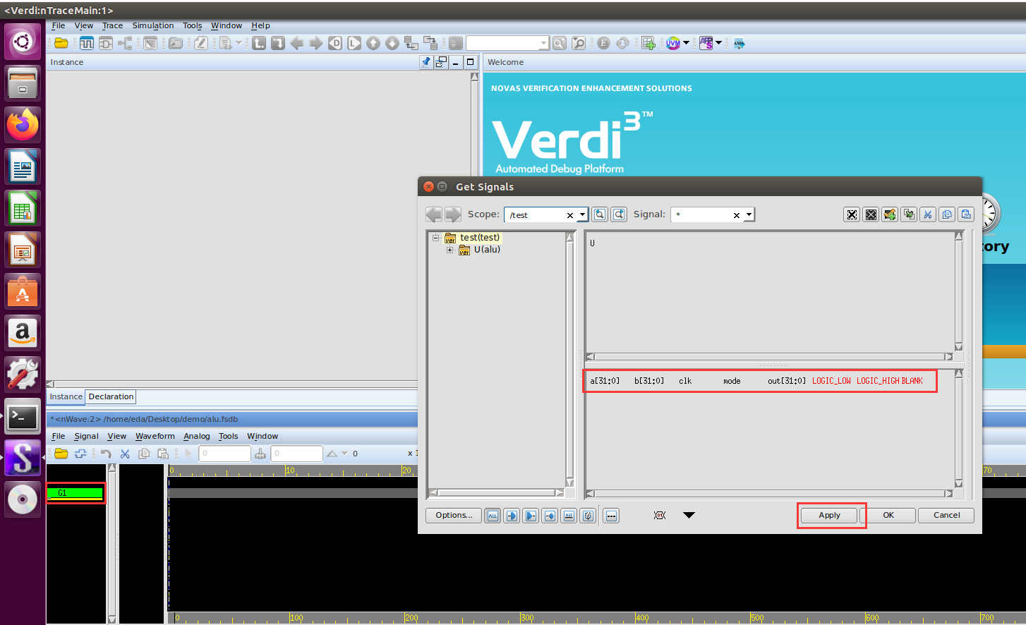
此时还没有波形,我们选择G1,按g,会跳出下图所示的一个框,在这个界面里,我们可以选中我们要观察的信号,然后点击apply.
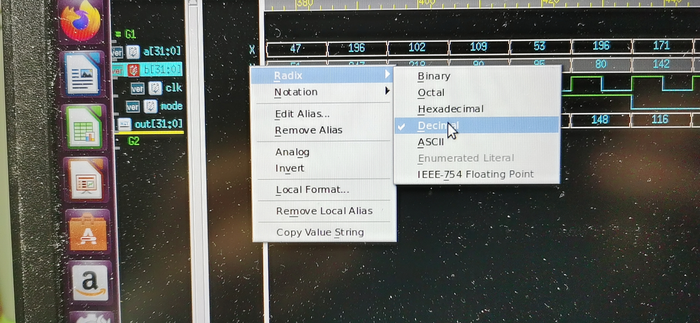
apply之后,会出现如下波形,在信号右侧区域右键,选择Radix,选择十进制,如下图所示:
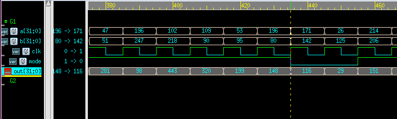
最终波形如下图所示
最后
以上就是开朗玉米最近收集整理的关于VCS和Verdi联合仿真编写RTL代码VCS编译Verdi查看波形的全部内容,更多相关VCS和Verdi联合仿真编写RTL代码VCS编译Verdi查看波形内容请搜索靠谱客的其他文章。


发表评论 取消回复