目录
-
项目要求
-
项目综合拓扑图
-
设备详情信息
-
设备配置详情
4.1. SW14.2. SW2
4.3. SW3
4.4. SW4
4.5. R1
4.6. R2
4.7. R3
1.项目要求
1.IP 地址配置如图,公司网络通过R1连接互联网;
2.SW1和SW2之间的直连链路配置链路聚合
3.公司内部业务网段为vlan10和vlan20; PC1和PC3属于vlan10, PC2和PC4属于vlan20,vlan30用于SW1和SW2建立OSPF邻居;vlan111为SW1和R1的互联vlan,vlan212为 SW2和R2的互联vlan
4.所有交换机相连的端口配置为trunk,不允许无关流量通过;。
5.交换机连接PC的端口配置为边缘端口。
6.SW1 和SW2上为vlan10和vlan20配置VRRP,虚拟IP主机位为254,SW1在vlan10是MASTER,在vlan20是BACKUP; SW2在vlan20是MASTER,在vlan10是BACKUP;要求MASTER设备优先级150,BACKUP 设备优先级为120,当连接路由器的接口故障,优先级降低40触发VRRP抢占。
7.按图示分区域配置OSPF实现公司内部网络全网互通,R1和R2的环回口宣告进骨干区域,业务网段不允许出现协议报文; SW1 和SW2只允许通过vlan30建立邻居关系。
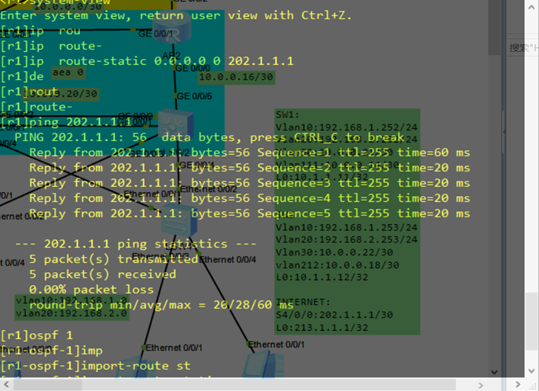
8.R1上配置默认路由指向互联网,并引入到OSPF
9.R1和INTERNET上配置双向chap验证,用户名和密码都为你的名字+1
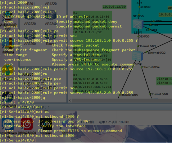
10.R1上配置EASYIP访问互联网,只有业务网段192.168.1.0/24和192.168.2.0/24 的数据
流可以访问互联网。
11.在SERVER1上开启www服务和FTP服务,要求vlan10可以访问www服务,但不能
访问FTP服务,vlan20可以访问FTP服务,但不能访问www服务。
12.R1开启telnet远程管理,使用能登录,用户名和密码都为你的名字,并且要求该用户有level 0的权限但是可以进入系统视图模式
2.项目综合拓扑图
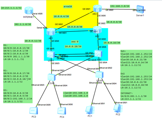
3.设备详情信息

4.设备配置详情
4.1. SW1
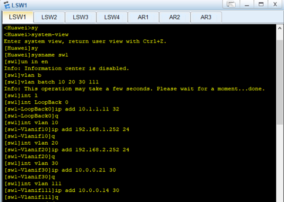
在SW1上创建所需要的vlan
[sw1]vlan b
[sw1]vlan batch 10 20 30 111
Info: This operation may take a few seconds. Please wait for a moment…done.
在SW1上添加vlan的ip地址
[sw1]int LoopBack 0
[sw1-LoopBack0]ip add 10.1.1.11 32
[sw1-LoopBack0]q
[sw1]int vlan 10
[sw1-Vlanif10]ip add 192.168.1.252 24
[sw1-Vlanif10]q
[sw1]int vlan 20
[sw1-Vlanif20]ip add 192.168.2.252 24
[sw1-Vlanif20]q
[sw1]int vlan 30
[sw1-Vlanif30]ip add 10.0.0.21 30
[sw1-Vlanif30]q
[sw1]int vlan 111
[sw1-Vlanif111]ip add 10.0.0.14 30
[sw1-Vlanif111]q
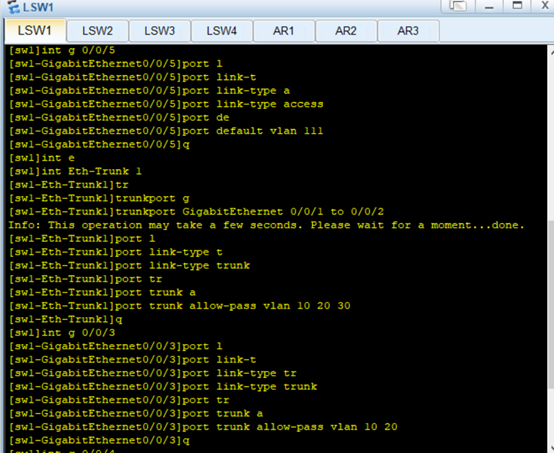
在sw1上为各个接口配置类型和vlan,0/0/1-2做链路聚合,后续做vrrp和生成树
[sw1]int g 0/0/5
[sw1-GigabitEthernet0/0/5]port link-type access
[sw1-GigabitEthernet0/0/5]port default vlan 111
[sw1-GigabitEthernet0/0/5]q
[sw1]int e
[sw1]int Eth-Trunk 1
[sw1-Eth-Trunk1]trunkport GigabitEthernet 0/0/1 to 0/0/2
Info: This operation may take a few seconds. Please wait for a moment…done.
[sw1-Eth-Trunk1]port link-type trunk
[sw1-Eth-Trunk1]port trunk allow-pass vlan 10 20 30
[sw1-Eth-Trunk1]q
[sw1]int g 0/0/3
[sw1-GigabitEthernet0/0/3]port link-type trunk
[sw1-GigabitEthernet0/0/3]port trunk allow-pass vlan 10 20
[sw1-GigabitEthernet0/0/3]q
[sw1]int g 0/0/4
[sw1-GigabitEthernet0/0/4]port link-type trunk
[sw1-GigabitEthernet0/0/4]port trunk allow-pass vlan 10 20
[sw1-GigabitEthernet0/0/4]q

在SW1上配置VLAN10,VLAN20的vrrp
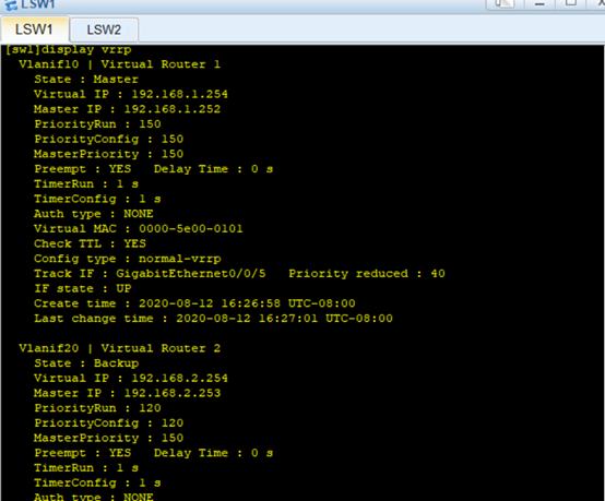
[sw1]int vlan 10
[sw1-Vlanif10]vrrp vrid 1 virtual-ip 192.168.1.254
[sw1-Vlanif10]vrrp vrid 1 priority 150
[sw1-Vlanif10]vrrp vrid 1 track interface GigabitEthernet 0/0/5 reduced 40
[sw1]int vlan 20
[sw1-Vlanif20]vrrp vrid 2 virtual-ip 192.168.2.254
[sw1-Vlanif20]vrrp vrid 2 priority 120
在SW1上display vrrp查看vrrp信息

在SW1上做区域0的OSPF,进行互通
[sw1]display ip interface b
*down: administratively down
^down: standby
(l): loopback
(s): spoofing
The number of interface that is UP in Physical is 7
The number of interface that is DOWN in Physical is 1
The number of interface that is UP in Protocol is 6
The number of interface that is DOWN in Protocol is 2
Interface IP Address/Mask Physical Protocol
LoopBack0 10.1.1.11/32 up up(s)
MEth0/0/1 unassigned down down
NULL0 unassigned up up(s)
Vlanif1 unassigned up down
Vlanif10 192.168.1.252/24 up up
Vlanif20 192.168.2.252/24 up up
Vlanif30 10.0.0.21/30 up up
Vlanif111 10.0.0.14/30 up up
跟R1操作一致,对着接口ip表进行宣告
查看在SW1上形成的和其它设备OSPF邻居关系

4.2. SW2
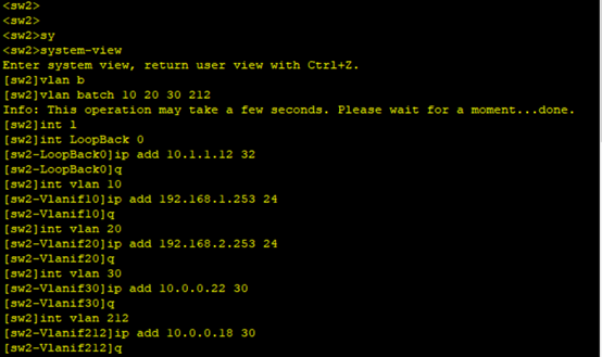
在SW2上创建所需要的vlan
[sw2]vlan batch 10 20 30 212
Info: This operation may take a few seconds. Please wait for a moment…done.
在SW2上添加vlan的ip地址
[sw2]int LoopBack 0
[sw2-LoopBack0]ip add 10.1.1.12 32
[sw2-LoopBack0]q
[sw2]int vlan 10
[sw2-Vlanif10]ip add 192.168.1.253 24
[sw2-Vlanif10]q
[sw2]int vlan 20
[sw2-Vlanif20]ip add 192.168.2.253 24
[sw2-Vlanif20]q
[sw2]int vlan 30
[sw2-Vlanif30]ip add 10.0.0.22 30
[sw2-Vlanif30]q
[sw2]int vlan 212
[sw2-Vlanif212]ip add 10.0.0.18 30
[sw2-Vlanif212]q
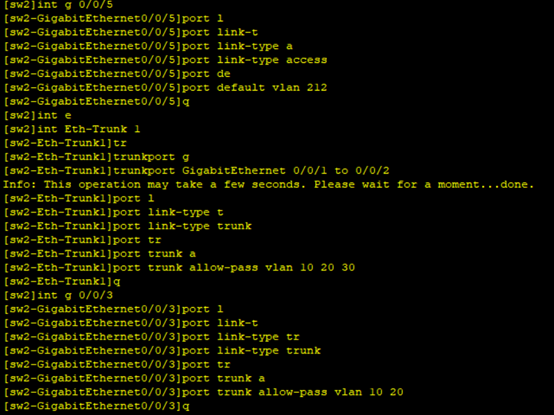
在sw2上为各个接口配置类型和vlan,0/0/1-2做链路聚合,后续做vrrp和生成树
[sw2]int g 0/0/5
[sw2-GigabitEthernet0/0/5]port link-type access
[sw2-GigabitEthernet0/0/5]port default vlan 212
[sw2-GigabitEthernet0/0/5]q
[sw2]int e
[sw2]int Eth-Trunk 1
[sw2-Eth-Trunk1]trunkport GigabitEthernet 0/0/1 to 0/0/2
Info: This operation may take a few seconds. Please wait for a moment…done.
[sw2-Eth-Trunk1]port link-type trunk
[sw2-Eth-Trunk1]port trunk allow-pass vlan 10 20 30
[sw2-Eth-Trunk1]q
[sw2]int g 0/0/3
[sw2-GigabitEthernet0/0/3]port link-type trunk
[sw2-GigabitEthernet0/0/3]port trunk allow-pass vlan 10 20
[sw2-GigabitEthernet0/0/3]q
[sw2]int g 0/0/4
[sw2-GigabitEthernet0/0/4]port link-type trunk
[sw2-GigabitEthernet0/0/4]port trunk allow-pass vlan 10 20
[sw2-GigabitEthernet0/0/4]q

在SW2上配置VLAN10,VLAN20的vrrp
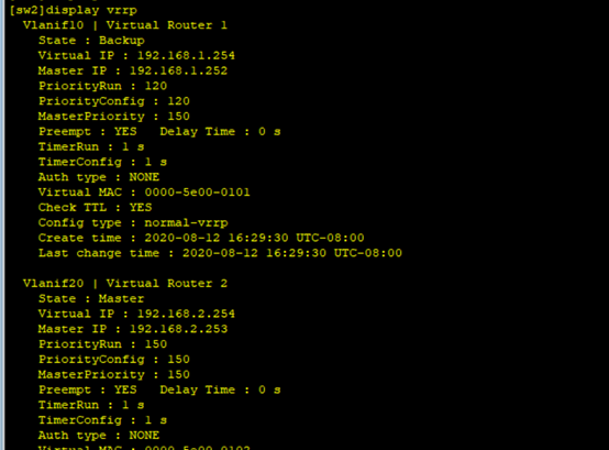
[sw2]int vlan 10
[sw2-Vlanif10]vrrp vrid 1 virtual-ip 192.168.1.254
[sw2-Vlanif10]vrrp vrid 1 priority 120
[sw2-Vlanif10]q
[sw2]int vlan 20
[sw2-Vlanif20]vrrp vrid 2 virtual-ip 192.168.2.254
[sw2-Vlanif20]vrrp vrid 2 priority 150
[sw2-Vlanif20]vrrp vrid 2 track interface GigabitEthernet 0/0/5 reduced 40
[sw2-Vlanif20]q
在SW1上display vrrp查看vrrp信息

在SW2上做区域0的OSPF,进行互通
[sw2]display IP interface B
*down: administratively down
^down: standby
(l): loopback
(s): spoofing
The number of interface that is UP in Physical is 7
The number of interface that is DOWN in Physical is 1
The number of interface that is UP in Protocol is 6
The number of interface that is DOWN in Protocol is 2
Interface IP Address/Mask Physical Protocol
LoopBack0 10.1.1.12/32 up up(s)
MEth0/0/1 unassigned down down
NULL0 unassigned up up(s)
Vlanif1 unassigned up down
Vlanif10 192.168.1.253/24 up up
Vlanif20 192.168.2.253/24 up up
Vlanif30 10.0.0.22/30 up up
Vlanif212 10.0.0.18/30 up up
跟R1操作一致,对着ip表进行宣告
查看在SW2上形成的和其它设备OSPF邻居关系

4.3. SW3
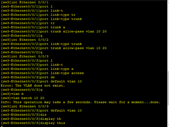
在SW3上创建所需vlan,配置接口类型和通过的vlan
[sw3]vlan batch 10 20
Info: This operation may take a few seconds. Please wait for a moment…done.
[sw3]int Ethernet 0/0/1
[sw3-Ethernet0/0/1]port link-type trunk
[sw3-Ethernet0/0/1]port trunk allow-pass vlan 10 20
[sw3-Ethernet0/0/1]q
[sw3]int Ethernet 0/0/2
[sw3-Ethernet0/0/2]port link-type trunk
[sw3-Ethernet0/0/2]port trunk allow-pass vlan 10 20
[sw3-Ethernet0/0/2]q
[sw3]int Ethernet 0/0/3
[sw3-Ethernet0/0/3]port link-type access
[sw3-Ethernet0/0/3]port default vlan 10
[sw3]int Ethernet 0/0/4
[sw3-Ethernet0/0/4]port link-type access
[sw3-Ethernet0/0/4]port default vlan 20
[sw3-Ethernet0/0/4]q

在SW3上配置边缘端口
[sw3]int e 0/0/3
[sw3-Ethernet0/0/3]stp edged-port enable
[sw3-Ethernet0/0/3]q
[sw3]int e 0/0/4
[sw3-Ethernet0/0/4]stp edged-port enable
[sw3-Ethernet0/0/4]q

4.4. SW4
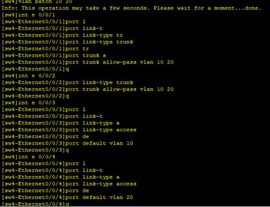
在SW3上创建所需vlan,配置接口类型和通过的vlan
[sw4]vlan batch 10 20
Info: This operation may take a few seconds. Please wait for a moment…done.
[sw4]int e 0/0/1
[sw4-Ethernet0/0/1]port link-type trunk
[sw4-Ethernet0/0/1]port trunk allow-pass vlan 10 20
[sw4-Ethernet0/0/1]q
[sw4]int e 0/0/2
[sw4-Ethernet0/0/2]port link-type trunk
[sw4-Ethernet0/0/2]port trunk allow-pass vlan 10 20
[sw4-Ethernet0/0/2]q
[sw4]int e 0/0/3
[sw4-Ethernet0/0/3]port link-type access
[sw4-Ethernet0/0/3]port default vlan 10
[sw4-Ethernet0/0/3]q
[sw4]int e 0/0/4
[sw4-Ethernet0/0/4]port link-type access
[sw4-Ethernet0/0/4]port default vlan 20
[sw4-Ethernet0/0/4]q
在SW4上配置边缘端口
[sw4]int e 0/0/3
[sw4-Ethernet0/0/3]stp edged-port enable
[sw4-Ethernet0/0/3]q
[sw4]int e 0/0/4
[sw4-Ethernet0/0/4]stp edged-port enable
[sw4-Ethernet0/0/4]q

4.5. R1
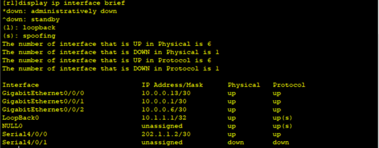
在R1上为各个接口添加IP地址
[r1]int g 0/0/0
[r1-GigabitEthernet0/0/0]ip add 10.0.0.13 30
[r1-GigabitEthernet0/0/0]q
[r1]int g 0/0/1
[r1-GigabitEthernet0/0/1]ip add 10.0.0.1 30
[r1-GigabitEthernet0/0/1]q
[r1]int g 0/0/2
[r1-GigabitEthernet0/0/2]ip add 10.0.0.6 30
[r1-GigabitEthernet0/0/2]q
[r1]int s4/0/0
[r1-Serial4/0/0]ip add 202.1.1.2 30
[r1-Serial4/0/0]q
[r1]int l0
[r1-LoopBack0]ip add 10.1.1.1 32
[r1-LoopBack0]q
在R1上做区域10和区域0的OSPF
[R1]ospf 1
[R1-ospf-1]area 10
[R1-ospf-1-area-0.0.0.10]dis
[R1-ospf-1-area-0.0.0.10]display ip in
[R1-ospf-1-area-0.0.0.10]display ip interface b
Interface IP Address/Mask Physical Protocol
GigabitEthernet0/0/0 10.0.0.13/30 up up
GigabitEthernet0/0/1 10.0.0.1/30 up up
GigabitEthernet0/0/2 10.0.0.6/30 up up
LoopBack0 10.1.1.1/32 up up(s)
NULL0 unassigned up up(s)
Serial4/0/0 202.1.1.2/30 up up
Serial4/0/1 unassigned down down
[R1-ospf-1-area-0.0.0.10]network 10.0.0.6 0.0.0.0
[R1-ospf-1-area-0.0.0.10]area 0
[R1-ospf-1-area-0.0.0.0]network 10.0.0.13 0.0.0.0
[R1-ospf-1-area-0.0.0.0]network 10.0.0.1 0.0.0.0
[R1-ospf-1-area-0.0.0.0]network 10.1.1.1 0.0.0.0
查看在R1上形成的和其它设备OSPF邻居关系

R1上配置默认路由指向互联网,并引入到OSPF
R1上配置EASYIP访问互联网,只有业务网段192.168.1.0/24和192.168.2.0/24 的数据
流可以访问互联网。
acl number 2000
rule 5 permit source 192.168.1.0 0.0.0.255
rule 10 permit source 192.168.2.0 0.0.0.255
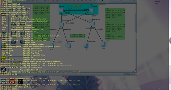
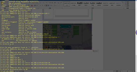
.在SERVER1上开启www服务和FTP服务,要求vlan10可以访问www服务,但不能
访问FTP服务,vlan20可以访问FTP服务,但不能访问www服务。
acl number 3000
rule 5 deny tcp source 192.168.1.0 0.0.0.255 destination 192.168.3.1 0 destination-port eq ftp
rule 10 deny tcp source 192.168.2.0 0.0.0.255 destination 192.168.3.1 0 destination-port eq www
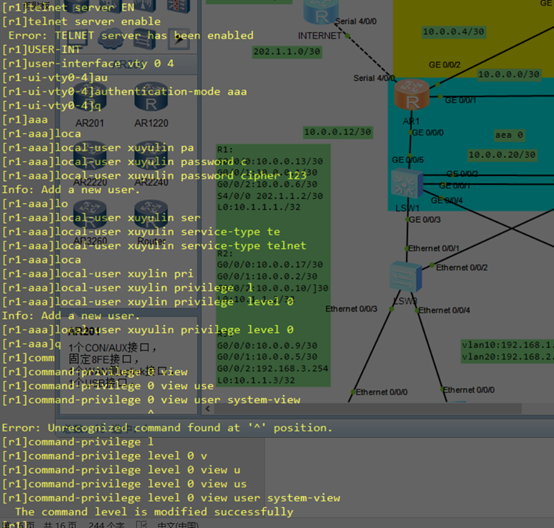
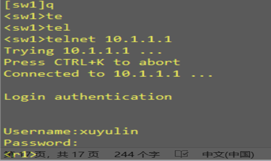
R1开启telnet远程管理,使用能登录,并且要求该用户有level 0的权限但是可以进入系统视图模式
R1和INTERNET上配置双向chap验证
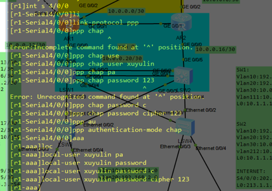
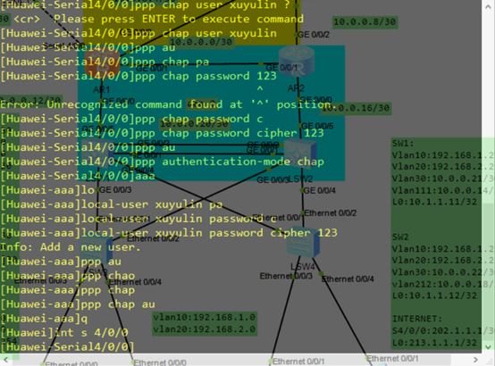
4.6. R2
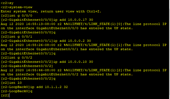
在R2上为各个接口添加IP地址
[r2]int g 0/0/0
[r2-GigabitEthernet0/0/0]ip add 10.0.0.17 30
[r2-GigabitEthernet0/0/0]q
[r2]int g 0/0/1
[r2-GigabitEthernet0/0/1]ip add 10.0.0.2 30
[r2-GigabitEthernet0/0/1]q
[r2]int g 0/0/2
[r2-GigabitEthernet0/0/2]ip add 10.0.0.10 30
[r2-GigabitEthernet0/0/2]
[r2-GigabitEthernet0/0/2]q
[r2]int l0
[r2-LoopBack0]ip add 10.1.1.2 32
[r2-LoopBack0]q
在R2上做区域10和区域0的OSPF
[R2]display ip interface b
*down: administratively down
^down: standby
(l): loopback
(s): spoofing
The number of interface that is UP in Physical is 5
The number of interface that is DOWN in Physical is 0
The number of interface that is UP in Protocol is 5
The number of interface that is DOWN in Protocol is 0
Interface IP Address/Mask Physical Protocol
GigabitEthernet0/0/0 10.0.0.17/30 up up
GigabitEthernet0/0/1 10.0.0.2/30 up up
GigabitEthernet0/0/2 10.0.0.10/30 up up
LoopBack0 10.1.1.2/32 up up(s)
NULL0 unassigned up up(s)
跟R1操作一致,对着ip表进行宣告
查看在R2上形成的和其它设备OSPF邻居关系

4.7. R3
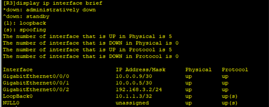
在R3上为各个接口添加IP地址
在R3上做区域10的OSPF
[R3]display ip interface brief
*down: administratively down
^down: standby
(l): loopback
(s): spoofing
The number of interface that is UP in Physical is 5
The number of interface that is DOWN in Physical is 0
The number of interface that is UP in Protocol is 5
The number of interface that is DOWN in Protocol is 0
Interface IP Address/Mask Physical Protocol
GigabitEthernet0/0/0 10.0.0.9/30 up up
GigabitEthernet0/0/1 10.0.0.5/30 up up
GigabitEthernet0/0/2 192.168.3.2/24 up up
LoopBack0 10.1.1.3/32 up up(s)
NULL0 unassigned up up(s)
跟R1操作一致,对着ip表进行宣告
查看在R3上形成的和其它设备OSPF邻居关系

最后
以上就是超帅洋葱最近收集整理的关于华为综合项目分析的全部内容,更多相关华为综合项目分析内容请搜索靠谱客的其他文章。


发表评论 取消回复