1、arduino的代码
生成脉冲信号并打印到串口
//生成脉冲信号
int i;
int k;
int j;
int num_1 = 0;
int num_2 = 0;
void setup() {
  //int num_1 = 0;
  pinMode(4,OUTPUT);
  Serial.begin(9600);
  Serial.println(" I coming!");

}

void loop() {
    for(i=1;i<10;i++)
  {
    digitalWrite(4,LOW);
    num_1 = digitalRead(4);//读取的是数字信号
    for(k=1;k<10;k++)     //读取模拟信号:analogRead()
    {
    Serial.println(num_1);
    delay(100);
    }
    digitalWrite(4,HIGH);
    num_2 = digitalRead(4);
    for(j=1;j<10;j++){
    Serial.println(num_2);
    delay(100);
    }
    }
}
2、MATLAB代码:创建为一个函数
功能:接收串口数据,并打印出来。
function Matlab_arduino(numero_1)%创建成一个函数,方便以后调用
close all;
clc;
y = zeros(1,1000);%创建一个1行,1000列的零矩阵
delete(instrfind({'Port'},{'COM6'}));
puerto_serial = serial('COM6');%查找通信接口对象并断开。
puerto.serial.BaudRate = 9600;%设置波特率
warning('off','MATLAB:serial:fscanf:unsuccessfulRead');%关闭警告信息
fopen(puerto_serial);%打开串口
%%绘图
contador_muestras = 1;
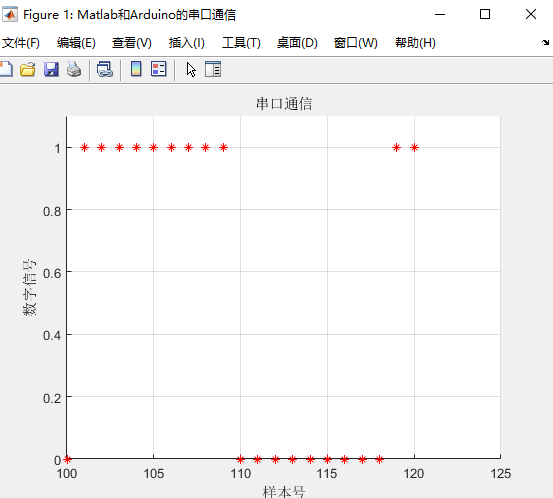
figure('Name','Matlab和Arduino的串口通信');
title('串口通信');
xlabel('样本号');
ylabel('数字信号');
grid on;
hold on;
while contador_muestras<=numero_1
ylim([0 1.1]);%设置Y轴的范围值
xlim([contador_muestras-20 contador_muestras+5]);%X轴的取值范围
valor_potenciometro = fscanf(puerto_serial,'%d');
y(contador_muestras) = (valor_potenciometro(1))*5/5;
plot(contador_muestras,y(contador_muestras),'*-g');
drawnow;%更新图像
contador_muestras = contador_muestras + 1;
pause(0.5);%更新时间
end
%%结束后关闭串口
fclose(puerto_serial);
delete(puerto_serial);
clear all;
clc;
end
显示结果:
[文件名:Matlab_arduino.m]
最后
以上就是忐忑银耳汤最近收集整理的关于Matlab与Arduino连接(二):MATLAB 和arduino的‘动态示波器’(复现)的全部内容,更多相关Matlab与Arduino连接(二):MATLAB内容请搜索靠谱客的其他文章。
本图文内容来源于网友提供,作为学习参考使用,或来自网络收集整理,版权属于原作者所有。


发表评论 取消回复