FPGA实现OFDM(三)- FEC编码器/多码率卷积码的FPGA实现
- 研究生 生活 下 fpga_blog->(1) : 最近做课题相关的太多了,跳出一下
上一篇:
FPGA实现OFDM(1)-OFDM原理
FPGA实现OFDM(二)-整体系统框架
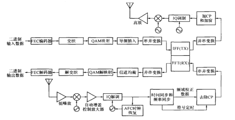
在上一篇中我们已经建模完整体的OFDM的R/T过程,这里我们开始从这个图开始,从发射机开始到接收机,一个个模块实现:

会和书中实现的顺序不一样.讲的代码也会有点不一样
文章目录
- FPGA实现OFDM(三)- FEC编码器/多码率卷积码的FPGA实现
- FEC编码器/卷积码生成
- 1/2码率ConvEncode模块
- DEMUX码率选择+BUF
- Puncture删余
- Index索引输出
- 结语
FEC编码器/卷积码生成
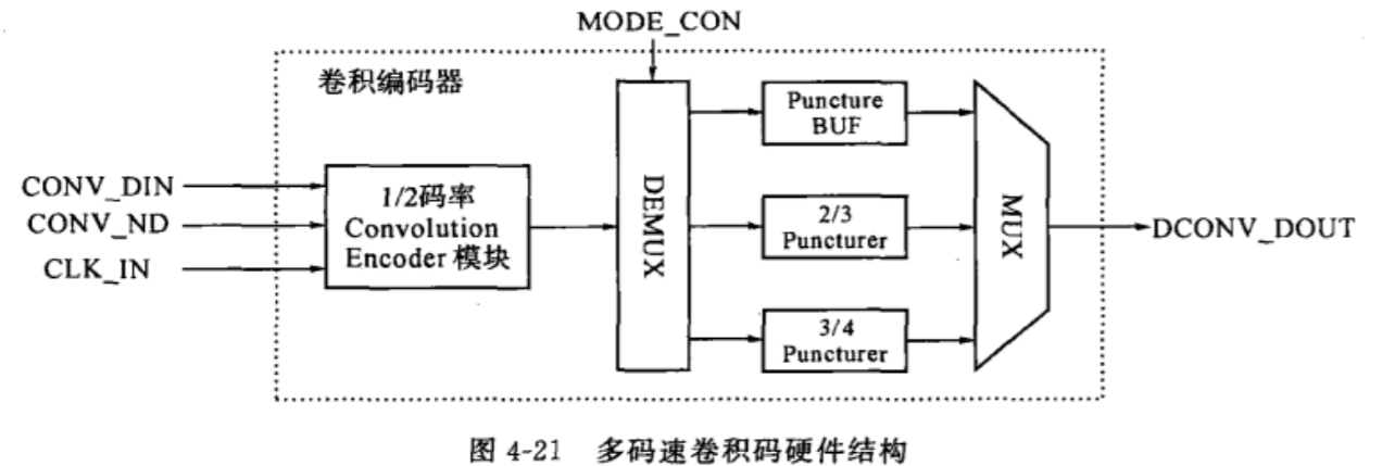
在上一篇中,重点介绍了卷积码的编码过程,和如何用1/2码率根据不同需求变换出不同的码率,所以在卷积码中,我们得到的硬件框图如下:

1/2码率ConvEncode模块
回顾一下上一篇博客,可知在802.11a中,规定卷积编码使用的生成多项式是 g 0 = 13 3 8 g_0=133_8 g0=1338和 g 1 = 17 1 8 g_1=171_8 g1=1718
即,生成多项式为:
S
(
x
)
=
x
6
+
x
5
+
x
3
+
x
2
+
1
g
0
S
(
x
)
=
x
6
+
x
3
+
x
2
+
x
1
+
1
g
1
begin{array}{l} S(x)=x^{6}+x^{5}+x^{3}+x^{2}+1quad g_0 \ S(x)=x^{6}+x^{3}+x^{2}+x^{1}+1quad g_1 end{array}
S(x)=x6+x5+x3+x2+1g0S(x)=x6+x3+x2+x1+1g1
所以这里的实现很简单,就是移位寄存器加两组模二加法多项式:
module conv_encoder(
    input aclr,			// async reset
	input clk,			// input clk
	input data_in,
	input nd,			// vaild sig
	output reg [1:0] data_out_v,
	output reg rdy		// ready sig
	);

reg [6:1] shift_reg;

always @ ( negedge aclr or posedge clk )
  begin
    if ( !aclr )
	   begin
		  shift_reg <= 6'b000000;
		  data_out_v <= 0;
		  rdy <= 0 ;
		end
    else
	   if ( nd )
		  begin
              data_out_v[0] <= shift_reg[6] + shift_reg[5] + shift_reg[3] + shift_reg[2] + data_in; // g0
              data_out_v[1] <= shift_reg[6] + shift_reg[3] + shift_reg[2] + shift_reg[1] + data_in; // g1

              shift_reg <= { shift_reg [5:1], data_in };	// shift reg

              rdy<=1;		// ready signal
		  end
		else
		  rdy <= 0;
  end
endmodule
需要注意的是,这里需要注意速率的匹配,这里输出的数据带宽是2bit的,所以在后面如果在并串转换中,需要一个2倍的时钟才能实现.其他的码率也是需要的.
DEMUX码率选择+BUF
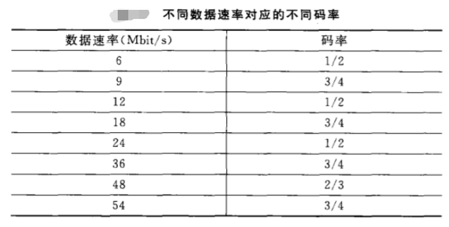
由于在OFDM中,不同速率对应不同码率,再盗一下上篇的图:

所以这个模块(电路)主要选择不同的删余模块和先将1/2的输出先存下来待处理:
先定义码率对应表(由RATE_CON控制):
	localparam CONV12_0 = 4'b1101;
	localparam CONV12_1 = 4'b0101;
	localparam CONV12_2 = 4'b1001;

	localparam CONV34_0 = 4'b1111;
	localparam CONV34_1 = 4'b0111;
	localparam CONV34_2 = 4'b1011;
	localparam CONV34_3 = 4'b0011;

	localparam CONV23_0 = 4'b0001;
所以这里对不同的BUF控制为:
always @ ( negedge DCONV_RST or posedge DCONV_CLK_I )	  // Put data into puncture_buffer.
	    begin:puncture_buffer
		    if ( ! DCONV_RST )
			    begin
				   Puncture_BUF_12 <= 0;
				 	Puncture_BUF_34 <= 0;
					Puncture_BUF_23 <= 0;
					i <= 0;
             end
          else
				 begin
				  if ( RDY )
					case ( RATE_CON )
					  CONV12_0,CONV12_1,CONV12_2:		// Rate is 1/2 .
					     begin
						    Puncture_BUF_12 <= DATA_OUT_V;
							 BUF_RDY <= 1;
						  end
					  CONV34_0,CONV34_1,CONV34_2,CONV34_3:	 // Rate is 3/4 .
					     begin
						     case (i)
							    2'b00:
								    begin
										Puncture_BUF_34 [1:0] <= DATA_OUT_V;
										BUF_RDY <= 1;
										i <= i + 1 ;
									 end
								 2'b01:
									 begin
										Puncture_BUF_34 [3:2] <= DATA_OUT_V;
										BUF_RDY <= 1;
										i <= i + 1 ;
									 end
								 2'b10:
									 begin
										Puncture_BUF_34 [5:4] <= DATA_OUT_V;
										BUF_RDY <= 1;
										i <= 2'b00 ;
									 end
								 default:
									 begin
										Puncture_BUF_34 <= 0;
										BUF_RDY <= 0;
										i <= 0;
									 end
							       endcase
                    end
					  CONV23_0:		 // Rate is 2/3 .
					     begin
							case ( i )
							2'b00:
								begin
									Puncture_BUF_23 [1:0] <= DATA_OUT_V;
									BUF_RDY <= 1;
									i <= i + 1 ;
								end
							2'b01:
								begin
									Puncture_BUF_23 [3:2] <= DATA_OUT_V;
									BUF_RDY <= 1;
									i <= 0 ;
								end
								default:
								begin
									Puncture_BUF_23 <= 0;
									BUF_RDY <= 0;
									i <= 0 ;
								end
                       endcase
                    end
					endcase
            else
				  begin
					 BUF_RDY <= 0;
					 Puncture_BUF_12 <= 0;
				 	 Puncture_BUF_34 <= 0;
					 Puncture_BUF_23 <= 0;
					 i <= 0;
              end
				end
      end
看起来很长,但是逻辑很简单,就是按时将1/2编码的输出按时序塞进BUF而已,都内置了一个一段式状态机,所以看起来很简单.注意这里的时钟是DCONV_CLK_I,与1/2卷积码编码的时钟是一致的
Puncture删余
在这个电路中主要实现删余和数据输出,所以在这里输入方会根据不同的码率提供不同的时钟,这一个是删余的关键
先贴代码(先无需细看):
always @ ( negedge DCONV_RST or posedge DCONV_CLK_O ) 	// Puncture and output the data.
    begin:Puncture
        if ( ! DCONV_RST )
            begin
                DCONV_DOUT <= 0 ;
                DCONV_RDY <= 0;
                j <= 3'b000;
            end

        else
            if ( BUF_RDY )
                case ( RATE_CON )
                    CONV12_0,CONV12_1,CONV12_2:		// Rate is 1/2 .
                        case ( j )
                            3'b000:begin
                                DCONV_DOUT <= Puncture_BUF_12 [j] ;
                                DCONV_RDY <= 1;
                                j <= j +1 ;
                            end
                            3'b001:begin
                                DCONV_DOUT <= Puncture_BUF_12 [j] ;
                                DCONV_RDY <= 1;
                                j <= 3'b000 ;
                            end
                            default:begin
                                DCONV_DOUT <= 0 ;
                                DCONV_RDY <= 0;
                                j <= 3'b000 ;
                            end
                        endcase
                    CONV34_0,CONV34_1,CONV34_2,CONV34_3:	 // Rate is 3/4 .
                        case (j)
                            3'b000,3'b001,3'b010:begin
                                DCONV_DOUT <= Puncture_BUF_34 [j] ;
                                DCONV_RDY <= 1;
                                j <= j + 1 ;
                            end
                            3'b011: begin
                                DCONV_DOUT <= Puncture_BUF_34 [j+2] ;
                                DCONV_RDY <= 1;
                                j <= 3'b000 ;
                            end
                            default: begin
                                DCONV_DOUT <= 0;
                                DCONV_RDY <= 0;
                                j <= 0;
                            end
                        endcase
                    CONV23_0:		 // Rate is 2/3 .
                        case ( j )
                            3'b000,3'b001:begin
                                DCONV_DOUT <= Puncture_BUF_23 [j] ;
                                DCONV_RDY <= 1;
                                j <= j + 1 ;
                            end
                            3'b010:begin
                                DCONV_DOUT <= Puncture_BUF_23 [j] ;
                                DCONV_RDY <= 1;
                                j <= 3'b000 ;
                            end
                            default:begin
                                DCONV_DOUT <= 0 ;
                                DCONV_RDY <= 0 ;
                                j <= 0 ;
                            end
                        endcase
                endcase
        else begin
            DCONV_DOUT <= 0 ;
            DCONV_RDY <= 0 ;
        end
    end
可以看见这里代码架构都差不多,但是这里最需要理解的是此时的输入时钟是外部根据不同码率提供的,那他怎么跟1/2编码中的时钟是怎么对应起来的,从而实现的删余的过程,以2/3为例:下面再回看代码,这里假设前面的编码时钟是60Mhz:
case ( j )	// 2/3 删余
    3'b000,3'b001:begin
        DCONV_DOUT <= Puncture_BUF_23 [j] ;
        DCONV_RDY <= 1;
        j <= j + 1 ;
	end
	3'b010:begin
        DCONV_DOUT <= Puncture_BUF_23 [j] ;
        DCONV_RDY <= 1;
        j <= 3'b000 ;
    end
default:begin
        DCONV_DOUT <= 0 ;
        DCONV_RDY <= 0 ;
        j <= 0 ;
    end
endcase
然而上面的代码部分所实现的显然是3/4删余,回想一下,由于在前面编码器出来的已经是1/2了,所以由小学数学:
R
a
t
e
=
1
2
3
4
=
2
3
Rate = frac{frac12} {frac34} = frac23
Rate=4321=32
显然此时输入带宽是(60MHz*2bit),由于删余的存在,由于删余和并串转换的存在,如果我们想实现3/4的输出时钟应该是:
60
∗
2
∗
3
4
(
M
H
z
∗
b
i
t
s
)
=
90
(
M
H
z
∗
b
i
t
s
)
60*2*frac{3}{4} (MHz*bits) = 90(MHz*bits)
60∗2∗43(MHz∗bits)=90(MHz∗bits)
输出位宽是1,所以可知输入时钟为90MHz.
注意这个和上一篇博客中所说的过程是不一样的,因为在FPGA中不可能在同一个编码过程中变换时钟.
Index索引输出
由于在后续中我们需要进行交织,他的本质约等于一个矩阵的转置,所以在这里输出的同时需要将当前编码的索引以一个模n计数器给输出.而且这个由于涉及到最终的输出(包括调制)的影响,所以在这个模n还需要根据不同的速率进行改变,所以等到交织的时候再讲吧.
实现的代码很简单,而这个n的选择会在下一篇博客中给出解析:
    always @ ( negedge DCONV_RST or posedge DCONV_CLK_O )  	 // Index output.
	    begin
		   if ( ! DCONV_RST )
		      begin
			    DCONV_INDEX <= 0 ;
				INDEX_TEMP <= 0;
			   end
			else begin
			  if ( BUF_RDY )
			     case ( RATE_CON )
				    CONV12_0,CONV34_0:begin
						if( INDEX_TEMP < 47 )
							begin
							INDEX_TEMP <= INDEX_TEMP + 1 ;
							DCONV_INDEX <= INDEX_TEMP ;
							end
						else
							begin
							INDEX_TEMP <= 0 ;
							DCONV_INDEX <= INDEX_TEMP ;
							end
                   end
				    CONV12_1,CONV34_1:begin
						if( INDEX_TEMP < 95 )
							begin
							INDEX_TEMP <= INDEX_TEMP + 1 ;
							DCONV_INDEX <= INDEX_TEMP ;
							end
						else
							begin
							INDEX_TEMP <= 0 ;
							DCONV_INDEX <= INDEX_TEMP ;
							end
                   end
				    CONV12_2,CONV34_2:begin
						if( INDEX_TEMP < 191 )
							begin
							INDEX_TEMP <= INDEX_TEMP + 1 ;
							DCONV_INDEX <= INDEX_TEMP ;
							end
						else
							begin
							INDEX_TEMP <= 0 ;
							DCONV_INDEX <= INDEX_TEMP ;
							end
                   end
				    CONV23_0,CONV34_3:begin
						if( INDEX_TEMP < 287 )
							begin
							INDEX_TEMP <= INDEX_TEMP + 1 ;
							DCONV_INDEX <= INDEX_TEMP ;
							end
						else
							begin
							INDEX_TEMP <= 0 ;
							DCONV_INDEX <= INDEX_TEMP ;
							end
                   end
				  endcase
			  else
			    DCONV_INDEX <= 0 ;
          end
		end
就是一个简单的计数器.
结语
由于研究生的关系,以后的更新篇幅都会比之前小一点,然后除了FPGA之外,会更一些ML,优化理论和通信的东西.
这系列的源码会在完结的时候给出,其实就是《XILINX FPGA的OFDM通信系统基带设计》这本书的附代码,虽然我可能会重写一些部分,但是大体的逻辑肯定是不可能由太大改动的,有兴趣的朋友可以一起看看.
也看见很多人问其他博客的代码,这些我随缘发吧,有一些写得早的当时的代码习惯还不是很可靠,所以我会在后面去再重构.有时候没时间就比较难了
如果你觉得有丶收获的话
最后
以上就是典雅鞋垫最近收集整理的关于FPGA实现OFDM(三)- 多码率卷积码的FPGA实现FPGA实现OFDM(三)- FEC编码器/多码率卷积码的FPGA实现的全部内容,更多相关FPGA实现OFDM(三)-内容请搜索靠谱客的其他文章。
![pytorch出现[WinError 1455] 页面文件太小,无法完成操作](https://www.shuijiaxian.com/files_image/reation/bcimg1.png)


发表评论 取消回复