使用软件:Cisco Packet Tracer
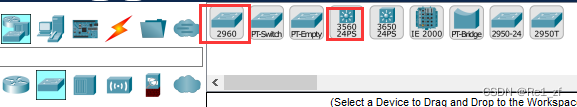
使用设备:PC机、cisco-2960交换机、cisco-3560-24PS交换机(有路由功能的三层交换机)
一、划分vlan
配置接线
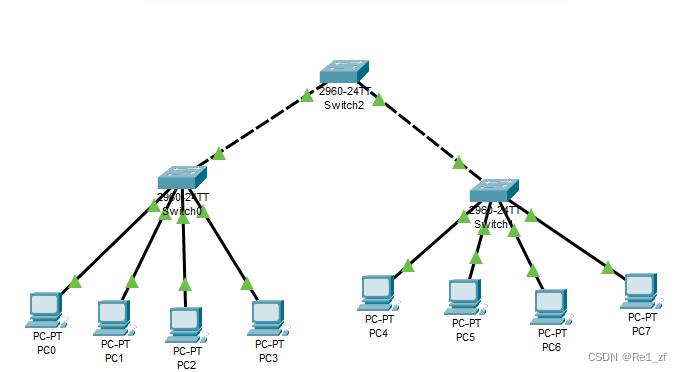
按图示连接好八个PC机,三个2960交换机
PC机与交换机之间用实线,交换机之间用虚线
switch0:
PC0连接f0/1
PC1连接f0/2
PC2连接f0/10
PC3连接f0/11
switch1:
PC4连接f0/1
PC5连接f0/2
PC6连接f0/10
PC7连接f0/11
依次配置八个PC机的IP地址
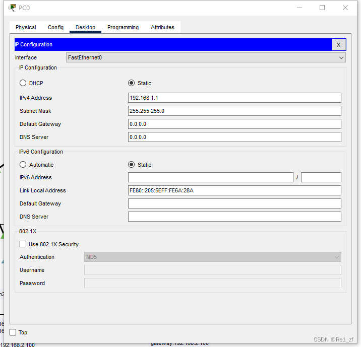
PC0:192.168.1.1

PC1:192.168.1.2

PC2:192.168.1.3

PC3:192.168.1.4

PC4:192.168.1.5

PC5:192.168.1.6

PC6:192.168.1.7

PC7:192.168.1.8
在交换机中进行配置划分vlan域
(所有接口默认均处在vlan1域中)
switch0命令:

Switch>enable
Switch#conf t
Enter configuration commands, one per line.  End with CNTL/Z.
Switch(config)#vlan 10
Switch(config-vlan)#vlan 20//创建两个vlan域
Switch(config-vlan)#int range f0/1-2
Switch(config-if-range)#switchport access vlan 10//将f0/1和f0/2接口划分到vlan10域中
Switch(config-if-range)#int range f0/10-11
Switch(config-if-range)#switchport access vlan 20//将f0/10和f0/11接口划分到vlan20域中
switch1命令:
Switch>enable
Switch#conf t
Enter configuration commands, one per line. End with CNTL/Z.
Switch(config)#vlan 10
Switch(config-vlan)#vlan 20//创建两个vlan域
Switch(config-vlan)#int range f0/1-2
Switch(config-if-range)#switchport access vlan 10//将f0/1和f0/2接口划分到vlan10域中
Switch(config-if-range)#int range f0/10-11
Switch(config-if-range)#switchport access vlan 20//将f0/10和f0/11接口划分到vlan20域中这样就将八台PC机划分为四个vlan域了
switch0和switch1下虽然都有vlan10,但是他们由于经过switch2,switch2暂时还没有配置,所有接口依旧处于vlan1域中,所以switch0与switch1两个交换机下的PC机虽然在同一vlan域,但是依旧不可互相通信
二、跨交换机vlan内通信
利用除连接PC机的另外一个交换机实现两个交换机下的PC之间的vlan内通信
其实只配置switch0和switch1就行,但是最好还是配置一下switch2,养成良好习惯,不然域扩大,配置不全,容易出bug
switch0命令:

Switch>enable
Switch#conf t
Enter configuration commands, one per line.  End with CNTL/Z.
Switch(config)#int g0/1
Switch(config-if)#switchport mode trunk
switch1命令:
Switch>enable
Switch#conf t
Enter configuration commands, one per line. End with CNTL/Z.
Switch(config)#int g0/1
Switch(config-if)#switchport mode trunkswitch2命令:
Switch>enable
Switch#conf t
Enter configuration commands, one per line. End with CNTL/Z.
Switch(config)#vlan 10
Switch(config-vlan)#vlan 20
Switch(config-vlan)#^Z
Switch#
%SYS-5-CONFIG_I: Configured from console by console
Switch#conf t
Enter configuration commands, one per line. End with CNTL/Z.
Switch(config)#int range f0/1-2
Switch(config-if-range)#switchport mode trunk
//出现下面情况就是启动了
Switch(config-if-range)#
%LINEPROTO-5-UPDOWN: Line protocol on Interface FastEthernet0/1, changed state to down
%LINEPROTO-5-UPDOWN: Line protocol on Interface FastEthernet0/1, changed state to up
%LINEPROTO-5-UPDOWN: Line protocol on Interface FastEthernet0/2, changed state to down
%LINEPROTO-5-UPDOWN: Line protocol on Interface FastEthernet0/2, changed state to up测试PC0能否与PC1、PC4、PC5通信(正常情况下应该是可以通信,因为同属vlan10)
测试PC2能否与PC3、PC6、PC7通信(正常情况下应该是可以通信,因为同属vlan20)
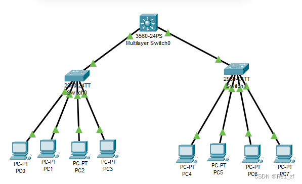
三、vlan间主机路由
更换switch2为cisco-3560交换机
cisco-3560命令:

Would you like to enter the initial configuration dialog? [yes/no]: no


Press RETURN to get started!


Switch>
Switch>enable
Switch#conf t
Enter configuration commands, one per line.  End with CNTL/Z.
Switch(config)#vlan 10
Switch(config-vlan)#vlan 20
Switch(config-vlan)#^Z
Switch#
Switch#conf t
Enter configuration commands, one per line.  End with CNTL/Z.
Switch(config)#ip routing
	//启动路由功能
Switch(config)#int vlan 10
Switch(config-if)#ip address 192.168.1.100 255.255.255.0
	//配置vlan域的网关
Switch(config-if)#no shutdown
Switch(config-if)#int vlan 20
Switch(config-if)#
%LINK-5-CHANGED: Interface Vlan20, changed state to up

%LINEPROTO-5-UPDOWN: Line protocol on Interface Vlan20, changed state to up

Switch(config-if)#ip address 192.168.2.100 255.255.255.0
Switch(config-if)#no shutdown 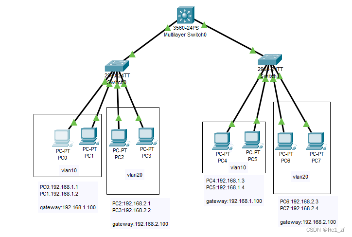
至此,vlan10与vlan20就划分为两个网段了
通信互不干扰
PC0与PC1、PC4、PC5及网关都可以正常通信
PC2与PC3、PC6、PC7及网关都可以正常通信
最后
以上就是温暖小土豆最近收集整理的关于划分vlan,实现跨vlan的trunk模式通信的全部内容,更多相关划分vlan,实现跨vlan内容请搜索靠谱客的其他文章。


发表评论 取消回复