ov2640 学习笔记
1 硬件
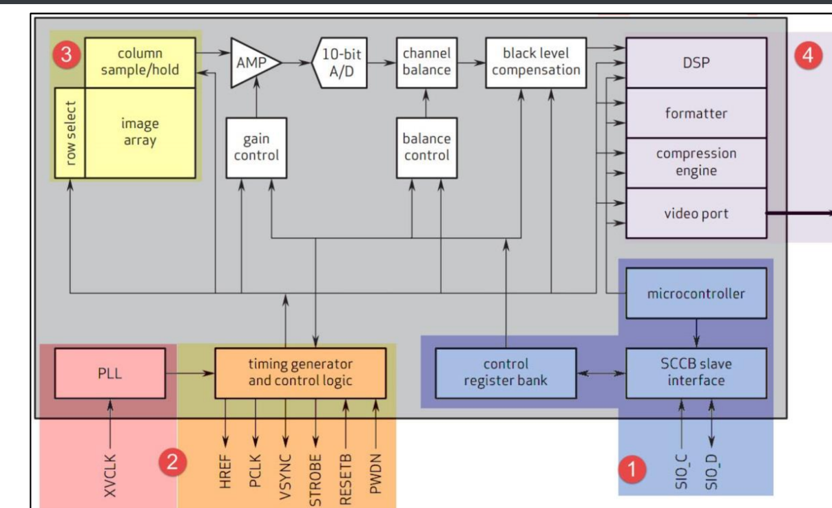
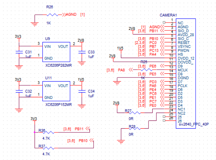
- 这是通用的DVP ov2640,需要用2个LDO供电, 我这里把AVDD和DVDD接在了一起, 为了剩成本, 如果专业点应该AVDD中间放一个磁珠, AGND和GND也要放磁珠, 或者单独供电
- SCCB类似IIC, 要上拉电阻
- PWDN是低电平使能
- VSYNC PCLK线尽量避免干扰, 否则出现花屏
- MCLK是ov2640的时钟输入, 相当于stm32的晶振一样, 一般是24M时钟, 这个可以用stm32的MCO输出时钟来提供, 也可以一个晶振来提供时钟
2 软件
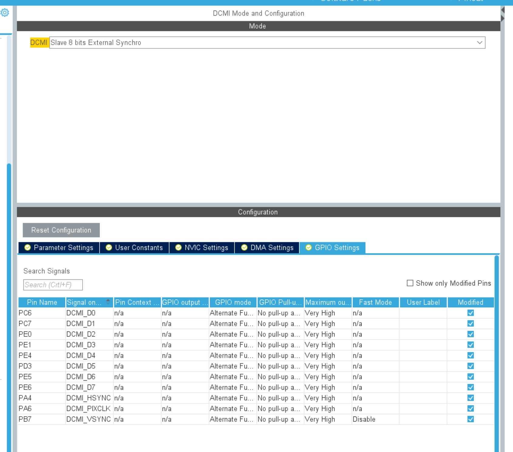


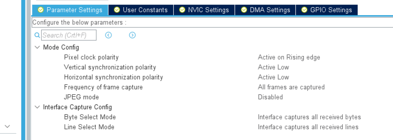
1 ov2640里面有两组寄存器, 分别是DSP和sensor的, 通过写0xff地址来区分

2 如果设置输出为RGB565, 那么需要传输2次才可以传输完一个像素点的数据. ov2640是可以设置先传输高字节和低字节的,在
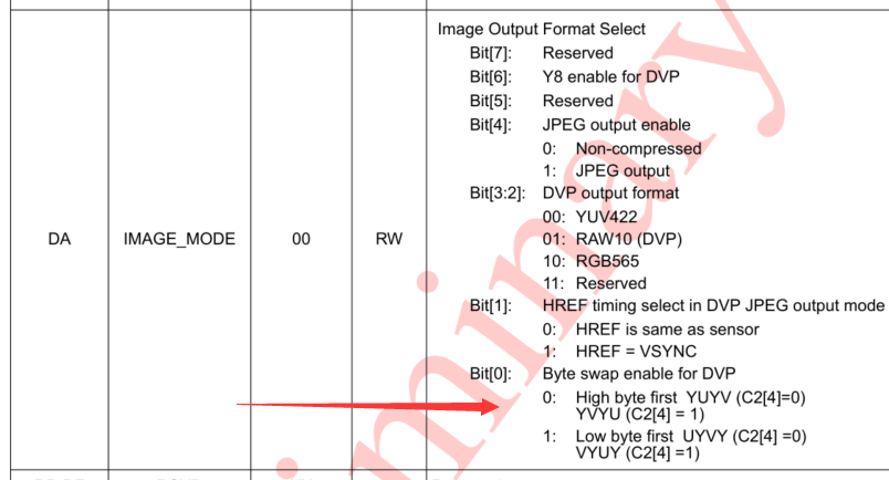
寄存器DA 0bit是设置LSB 和MSB的, 如果发现颜色不对 就检查一下这个位是否设置正确.
建议设置为LSB模式, 因为stm32是小端模式, 例如0x1234 , 在内存里面是先放34 ,再发12
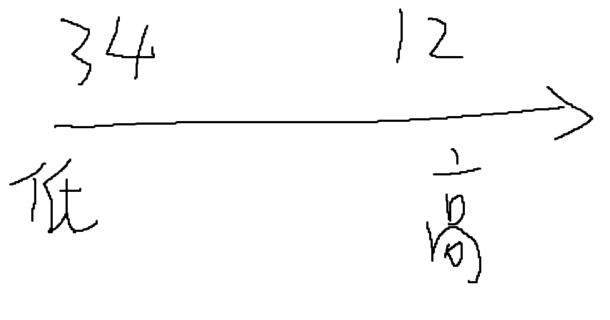
如果ov2640设置为LSB模式, 那么比如 0x780F // 紫色 , 第一次传输的就是0x0F ,第二次是0x78
用DMA往内存里面传输, 就是下面的这个格式
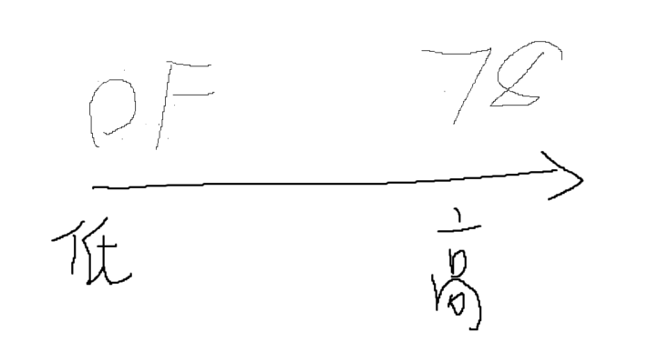
用一个uint16_t 变量去读取这个地址, 刚刚好是0x780F 也就是紫色. 如果这个地址是LCD的显存地址,那么LCD就可以直接刷新,而不需要去转换字节顺序. 这个在MCU LCD和RGB LCD都适用
其他就没啥好说的了,贴一下整理的ov2640寄存器
#ifndef __REG_REGS_H__
#define __REG_REGS_H__

#include <stdint.h>

/* DSP register bank FF=0x00*/

#define QS                      0x44   /* Quantization Scale Factor */
#define HSIZE                   0x51 /* H_SIZE[7:0] (real/4) */
#define VSIZE                   0x52  /* V_SIZE[7:0] (real/4) */
#define XOFFL                   0x53 /* OFFSET_X[7:0] */
#define YOFFL                   0x54 /* OFFSET_Y[7:0] */
#define VHYX                    0x55 /* Offset and size completion */
#define DPRP                    0x56
#define TEST                    0x57  /* Horizontal size completion */
#define ZMOW                    0x5A /* Zoom: Out Width  OUTW[7:0] (real/4) */
#define ZMOH                    0x5B /* Zoom: Out Height OUTH[7:0] (real/4) */
#define ZMHH                    0x5C /* Zoom: Speed and H&W completion */
#define BPADDR                  0x7C /* SDE Indirect Register Access: Address */
#define BPDATA                  0x7D /* SDE Indirect Register Access: Data */
#define SIZEL                   0x8C  /* Image Size Completion */
#define HSIZE8                  0xC0  /* Image Horizontal Size HSIZE[10:3] */
#define VSIZE8                  0xC1  /* Image Vertical Size VSIZE[10:3] */
#define CTRL1                   0xC3 /* DSP Module enable 1 */
#define MS_SP                   0xF0 /* SCCB Master Speed */
#define SS_ID                   0xF7 /* SCCB Slave ID */
#define SS_CTRL                 0xF7 /* SCCB Slave Control */
#define MC_AL                   0xFA
#define MC_AH                   0xFB
#define MC_D                    0xFC
#define P_CMD                   0xFD
#define P_STATUS                0xFE

// DSP module endable 1
#define CTRLI                   0x50
#define CTRLI_LP_DP             0x80
#define CTRLI_ROUND             0x40

// DSP module endable 0
#define CTRL0                   0xC2
#define CTRL0_AEC_EN            0x80
#define CTRL0_AEC_SEL           0x40
#define CTRL0_STAT_SEL          0x20
#define CTRL0_VFIRST            0x10
#define CTRL0_YUV422            0x08
#define CTRL0_YUV_EN            0x04
#define CTRL0_RGB_EN            0x02
#define CTRL0_RAW_EN            0x01

// DSP module endable 2
#define CTRL2                   0x86
#define CTRL2_DCW_EN            0x20
#define CTRL2_SDE_EN            0x10
#define CTRL2_UV_ADJ_EN         0x08
#define CTRL2_UV_AVG_EN         0x04
#define CTRL2_CMX_EN            0x01

// DSP module endable 3
#define CTRL3                   0x87
#define CTRL3_BPC_EN            0x80
#define CTRL3_WPC_EN            0x40
#define R_DVP_SP                0xD3
#define R_DVP_SP_AUTO_MODE      0x80

// bypass DSP
#define R_BYPASS                0x05
#define R_BYPASS_DSP_EN         0x00
#define R_BYPASS_DSP_BYPAS      0x01

// img output format select
#define IMAGE_MODE              0xDA
#define IMAGE_MODE_Y8_DVP_EN    0x40
#define IMAGE_MODE_JPEG_EN      0x10
#define IMAGE_MODE_YUV422       0x00
#define IMAGE_MODE_RAW10        0x04
#define IMAGE_MODE_RGB565       0x08
#define IMAGE_MODE_HREF_VSYNC   0x02
#define IMAGE_MODE_LBYTE_FIRST  0x01
#define IMAGE_MODE_GET_FMT(x)   ((x)&0xC)

// reset
#define REG_RESET                   0xE0
#define REG_RESET_MICROC            0x40
#define REG_RESET_SCCB              0x20
#define REG_RESET_JPEG              0x10
#define REG_RESET_DVP               0x04
#define REG_RESET_IPU               0x02
#define REG_RESET_CIF               0x01


/* Microcontroller misc register */
#define MC_BIST                 0xF9
#define MC_BIST_RESET           0x80
#define MC_BIST_BOOT_ROM_SEL    0x40
#define MC_BIST_12KB_SEL        0x20
#define MC_BIST_12KB_MASK       0x30
#define MC_BIST_512KB_SEL       0x08
#define MC_BIST_512KB_MASK      0x0C
#define MC_BIST_BUSY_BIT_R      0x02
#define MC_BIST_MC_RES_ONE_SH_W 0x02
#define MC_BIST_LAUNCH          0x01

/* Register Bank Select */
#define BANK_SEL                0xFF
#define BANK_SEL_DSP            0x00
#define BANK_SEL_SENSOR         0x01

/* Sensor register bank FF=0x01*/

#define GAIN                0x00  /* AGC - Gain control gain setting */
#define COM1                0x03   /* Common control 1 */
#define REG_PID             0x0A
#define REG_VER             0x0B
#define COM4                0x0D
#define AEC                 0x10

#define CLKRC               0x11
#define CLKRC_DOUBLE        0x80
#define CLKRC_2X_UXGA       (0x01 | CLKRC_DOUBLE)
#define CLKRC_2X_SVGA       CLKRC_DOUBLE
#define CLKRC_2X_CIF        CLKRC_DOUBLE
#define CLKRC_DIVIDER_MASK  0x3F

/* Common control 10 */
#define COM10               0x15
#define HSTART              0x17  /* Horizontal Window start MSB 8 bit */
#define HSTOP               0x18  /* Horizontal Window end MSB 8 bit */
#define VSTART              0x19  /* Vertical Window start MSB 8 bit */
#define VSTOP               0x1A  /* Vertical Window end MSB 8 bit */
#define MIDH                0x1C  /* Manufacturer ID byte - high */
#define MIDL                0x1D  /* Manufacturer ID byte - low  */
#define AEW                 0x24  /* AGC/AEC - Stable operating region (upper limit) */
#define AEB                 0x25  /* AGC/AEC - Stable operating region (lower limit) */
#define REG2A               0x2A   /* Dummy pixel insert MSB */
#define FRARL               0x2B  /* Dummy pixel insert LSB */
#define ADDVSL              0x2D   /* LSB of insert dummy lines in Vertical direction */
#define ADDVSH              0x2E  /* MSB of insert dummy lines in Vertical direction */
#define YAVG                0x2F /* Y/G Channel Average value */
#define HSDY                0x30
#define HEDY                0x31
#define ARCOM2              0x34
/* Register 45 */
#define REG45               0x45
#define FLL                 0x46  /* Frame Length Adjustment LSBs */
#define FLH                 0x47  /* Frame Length Adjustment MSBs */

 /* Zoom: Vertical start point */
#define COM19               0x48
#define ZOOMS               0x49  /* Zoom: Vertical start point */
#define COM22               0x4B /* Flash light control */
#define COM25               0x4E  /* For Banding operations */
#define BD50                0x4F  /* 50Hz Banding AEC 8 LSBs */
#define BD60                0x50  /* 60Hz Banding AEC 8 LSBs */
#define REG5D               0x5D  /* AVGsel[7:0],   16-zone average weight option */
#define REG5E               0x5E
#define REG5F               0x5F
#define REG60               0x60
#define HISTO_LOW           0x61 /* Histogram Algorithm Low Level */
#define HISTO_HIGH          0x62 /* Histogram Algorithm High Level */

/* Register 04 */
#define REG04               0x04
#define REG04_DEFAULT       0x28
#define REG04_HFLIP_IMG     0x80  /* Horizontal mirror image ON/OFF */
#define REG04_VFLIP_IMG     0x40  /* Vertical flip image ON/OFF */
#define REG04_VREF_EN       0x10
#define REG04_HREF_EN       0x08
#define REG04_SET(x)        (REG04_DEFAULT|x)

/* Frame Exposure One-pin Control Pre-charge Row Num */
#define REG08               0x08
/* Common control 2 */
#define COM2                0x09
#define COM2_STDBY          0x10  /* Soft sleep mode */
#define COM2_OUT_DRIVE_1x   0x00
#define COM2_OUT_DRIVE_2x   0x01
#define COM2_OUT_DRIVE_3x   0x02
#define COM2_OUT_DRIVE_4x   0x03

/* Common control 3 */
#define COM3                0x0C
#define COM3_DEFAULT        0x38
#define COM3_BAND_50Hz      0x04  /* 0 For Banding at 60H */
#define COM3_BAND_60Hz      0x00
#define COM3_BAND_AUTO      0x02  /* Auto Banding */
#define COM3_BAND_SET(x)    (COM3_DEFAULT|x)

/* Common control 7 */
#define COM7                0x12
/* Initiates system reset. All registers are
* set to factory default values after which
* the chip resumes normal operation */
#define COM7_SRST           0x80
#define COM7_RES_UXGA       0x00 /* UXGA */
#define COM7_RES_SVGA       0x40 /* SVGA */
#define COM7_RES_CIF        0x20 /* CIF  */
#define COM7_ZOOM_EN        0x04 /* Enable Zoom */
#define COM7_COLOR_BAR      0x02 /* Enable Color Bar Test */
#define COM7_GET_RES(x)     ((x)&0x70)

/* Common control 8 */
#define COM8                0x13
#define COM8_DEFAULT        0xC0
#define COM8_BNDF_EN        0x20 /* Enable Banding filter */
#define COM8_AGC_EN         0x04 /* AGC Auto/Manual control selection */
#define COM8_AEC_EN         0x01 /* Auto/Manual Exposure control */
#define COM8_SET(x)         (COM8_DEFAULT|x)
#define COM8_SET_AEC(r,x)   (((r)&0xFE)|((x)&1))

#define COM9                0x14 /* AGC gain ceiling */
#define COM9_DEFAULT        0x08
#define COM9_AGC_GAIN_2x    0x00 /* AGC:    2x */
#define COM9_AGC_GAIN_4x    0x01 /* AGC:    4x */
#define COM9_AGC_GAIN_8x    0x02 /* AGC:    8x */
#define COM9_AGC_GAIN_16x   0x03 /* AGC:   16x */
#define COM9_AGC_GAIN_32x   0x04 /* AGC:   32x */
#define COM9_AGC_GAIN_64x   0x05 /* AGC:   64x */
#define COM9_AGC_GAIN_128x  0x06 /* AGC:  128x */
#define COM9_AGC_SET(x)     (COM9_DEFAULT|(x<<5))

#define CTRL1_AWB           0x08 /* Enable AWB */

#define VV                  0x26
#define VV_AGC_TH_SET(h,l)  ((h<<4)|(l&0x0F))

#define REG32               0x32
#define REG32_UXGA          0x36
#define REG32_SVGA          0x09
#define REG32_CIF           0x00

#define VAL_SET(x, mask, rshift, lshift) ((((x) >> rshift) & mask) << lshift)

#define CTRLI_V_DIV_SET(x)      VAL_SET(x, 0x3, 0, 3)
#define CTRLI_H_DIV_SET(x)      VAL_SET(x, 0x3, 0, 0)

#define SIZEL_HSIZE8_11_SET(x)  VAL_SET(x, 0x1, 11, 6)
#define SIZEL_HSIZE8_SET(x)     VAL_SET(x, 0x7, 0, 3)
#define SIZEL_VSIZE8_SET(x)     VAL_SET(x, 0x7, 0, 0)

#define HSIZE8_SET(x)           VAL_SET(x, 0xFF, 3, 0)
#define VSIZE8_SET(x)           VAL_SET(x, 0xFF, 3, 0)

#define HSIZE_SET(x)            VAL_SET(x, 0xFF, 2, 0)
#define VSIZE_SET(x)            VAL_SET(x, 0xFF, 2, 0)

#define XOFFL_SET(x)            VAL_SET(x, 0xFF, 0, 0)
#define YOFFL_SET(x)            VAL_SET(x, 0xFF, 0, 0)

#define VHYX_VSIZE_SET(x)       VAL_SET(x, 0x1, (8+2), 7)
#define VHYX_HSIZE_SET(x)       VAL_SET(x, 0x1, (8+2), 3)
#define VHYX_YOFF_SET(x)        VAL_SET(x, 0x3, 8, 4)
#define VHYX_XOFF_SET(x)        VAL_SET(x, 0x3, 8, 0)

#define TEST_HSIZE_SET(x)       VAL_SET(x, 0x1, (9+2), 7)

#define ZMOW_OUTW_SET(x)        VAL_SET(x, 0xFF, 2, 0)
#define ZMOH_OUTH_SET(x)        VAL_SET(x, 0xFF, 2, 0)

#define ZMHH_ZSPEED_SET(x)      VAL_SET(x, 0x0F, 0, 4)
#define ZMHH_OUTH_SET(x)        VAL_SET(x, 0x1, (8+2), 2)
#define ZMHH_OUTW_SET(x)        VAL_SET(x, 0x3, (8+2), 0)


#define CIF_WIDTH                   (400)
#define CIF_HEIGHT                  (296)
#define SVGA_WIDTH                  (800)
#define SVGA_HEIGHT                 (600)
#define UXGA_WIDTH                  (1600)
#define UXGA_HEIGHT                 (1200)
#define SVGA_HSIZE                  (800)
#define SVGA_VSIZE                  (600)
#define UXGA_HSIZE                  (1600)
#define UXGA_VSIZE                  (1200)

extern const uint8_t OV2640_default_regs[][2];
extern const uint8_t ov2640_reg_tables[][2];

extern const uint8_t OV2640_svga_regs[][2];
extern const uint8_t OV2640_uxga_regs[][2];

#endif //__REG_REGS_H__
项目地址
https://github.com/KiritoGoLeon/EembeddedBoard/tree/master/stm32_h750_board_Io
最后
以上就是喜悦大地最近收集整理的关于stm32 ov2640硬件软件笔记的全部内容,更多相关stm32内容请搜索靠谱客的其他文章。
本图文内容来源于网友提供,作为学习参考使用,或来自网络收集整理,版权属于原作者所有。


发表评论 取消回复