3D目标检测基础知识
- 如何描述3D空间中的一个物体
- 空间坐标变换
- 平移矩阵
- 旋转矩阵
- 复合变换矩阵
- 坐标系
- 偏航角、观测角、目标方位角的关系
- 数据集
- NuScenes
- 点云数据原始格式
- 坐标转换
- 基本原则
- 两个坐标系之间如何转换
- 多传感器融合时的坐标转换
- 数据预处理
- Kitti
- REFERENCES
如何描述3D空间中的一个物体
-
位置
即xyz坐标 -
大小
lwh长宽高,即3D 框的尺寸 (x_size, y_size, z_size),按惯例定义为物体 3D 框在航向角 yaw 角度为 0 时沿着 x, y, z 轴三个方向的长度 -
姿态
三种表达方式:欧拉角、旋转矩阵、四元数-
欧拉角
分为pitch俯仰角、yaw航向角(偏航角)、roll翻滚角。车辆等地面上的物体,一般不会发生翻转和倾斜,
因此一般只用考虑航向角。
航向角的定义:选择一个轴作为重力轴,在垂直于重力轴的平面上选择一个参考方向,则参考方向的朝向角 yaw 为 0,朝向角沿着顺时针方向增大。如下图,z轴为重力轴,参考方向为y轴, 车辆前进方向与参考方向y轴的夹角则为yaw。需要注意是的,下图的坐标轴是基于车辆坐标系,即x轴向前,y轴向左,z轴向上。
-
旋转矩阵
一个坐标系中的坐标在另一个坐标系中表示的转换关系 -
四元数
(w,x,y,z),参考姿态的不同表示
-
空间坐标变换
用角度变换关系(rotation)可以表示在参考坐标系下物体的姿态,除了角度变化之外,还有一种是参考系原点的相对位置关系,一般用平移矩阵(translation)来表示
关于四元数、旋转矩阵、平移矩阵、复合变换矩阵的定义及关系,convert_nuScenes.py 文件代码详解中的三、main 函数部分有详细介绍,便于连贯阅读,下面直接引用了上述内容
平移矩阵
已知空间中的一个点
P
0
(
x
0
,
y
0
,
z
0
)
P_{0}(x_{0}, y_{0}, z_{0})
P0(x0,y0,z0), 然后将
P
0
P_{0}
P0沿着X轴、Y轴、Z轴平移
t
x
、
t
y
、
t
z
t_{x}、t_{y}、t_{z}
tx、ty、tz的距离,得到点
P
1
(
x
1
,
y
1
,
z
1
)
P_{1}(x_{1}, y_{1}, z_{1})
P1(x1,y1,z1),那么此过程可以用平移矩阵表示为
P
1
=
T
r
a
n
s
l
a
t
i
o
n
M
a
t
r
i
x
⋅
P
0
P1 = TranslationMatrix cdot P0
P1=TranslationMatrix⋅P0, 即
P
0
P_{0}
P0左乘一个平移矩阵得到
P
1
P_{1}
P1
[
x
1
y
1
z
1
1
]
=
[
x
0
+
t
x
y
0
+
t
y
z
0
+
t
z
1
]
=
[
1
0
0
t
x
0
1
0
t
y
0
0
1
t
z
0
0
0
1
]
[
x
0
y
0
z
0
1
]
left[begin{array}{c} mathrm{x}_{1} \ mathrm{y}_{1} \ mathrm{z}_{1} \ 1 end{array}right]=left[begin{array}{c} mathrm{x}_{0}+mathrm{t}_{mathrm{x}} \ mathrm{y}_{0}+mathrm{t}_{mathrm{y}} \ mathrm{z}_{0}+mathrm{t}_{mathrm{z}} \ 1 end{array}right]=left[begin{array}{cccc} 1 & 0 & 0 & mathrm{t}_{mathrm{x}} \ 0 & 1 & 0 & mathrm{t}_{mathrm{y}} \ 0 & 0 & 1 & mathrm{t}_{mathrm{z}} \ 0 & 0 & 0 & 1 end{array}right]left[begin{array}{c} mathrm{x}_{0} \ mathrm{y}_{0} \ mathrm{z}_{0} \ 1 end{array}right]
x1y1z11
=
x0+txy0+tyz0+tz1
=
100001000010txtytz1
x0y0z01
其中平移矩阵定义为
T
r
a
n
s
l
a
t
i
o
n
M
a
t
r
i
x
=
[
1
0
0
t
x
0
1
0
t
y
0
0
1
t
z
0
0
0
1
]
TranslationMatrix = left[begin{array}{cccc} 1 & 0 & 0 & mathrm{t}_{mathrm{x}} \ 0 & 1 & 0 & mathrm{t}_{mathrm{y}} \ 0 & 0 & 1 & mathrm{t}_{mathrm{z}} \ 0 & 0 & 0 & 1 end{array}right]
TranslationMatrix=
100001000010txtytz1
旋转矩阵
四元素、旋转矩阵都是用来描述刚体的姿态信息,只不过表达形式不同,它们之间可以通过数学公式进行换算,而这里就需要把四元素转换成旋转矩阵,因为后面需要使用旋转矩阵进行相应的计算
已知四元数
Q
u
a
t
e
r
n
i
o
n
=
(
w
,
x
,
y
,
z
)
Quaternion = (w, x, y, z)
Quaternion=(w,x,y,z)
则可以转换为如下旋转矩阵
R
o
t
a
t
i
o
n
M
a
t
r
i
x
=
[
w
2
+
x
2
−
y
2
−
z
2
2
(
x
y
−
w
z
)
2
(
x
z
+
w
y
)
2
(
x
y
+
w
z
)
w
2
−
x
2
+
y
2
−
z
2
2
(
y
z
−
w
x
)
2
(
x
z
−
w
y
)
2
(
y
z
+
w
x
)
w
2
−
x
2
−
y
2
+
z
2
]
RotationMatrix = left[begin{array}{ccc} w^{2}+x^{2}-y^{2}-z^{2} & 2(x y-w z) & 2(x z+w y) \ 2(x y+w z) & w^{2}-x^{2}+y^{2}-z^{2} & 2(y z-w x) \ 2(x z-w y) & 2(y z+w x) & w^{2}-x^{2}-y^{2}+z^{2} end{array}right]
RotationMatrix=
w2+x2−y2−z22(xy+wz)2(xz−wy)2(xy−wz)w2−x2+y2−z22(yz+wx)2(xz+wy)2(yz−wx)w2−x2−y2+z2
已知空间中的一个点
P
0
(
x
0
,
y
0
,
z
0
)
P_{0}(x_{0}, y_{0}, z_{0})
P0(x0,y0,z0),然后将
P
0
P_{0}
P0绕着X轴、Y轴、Z轴旋转不同的角度时(假设旋转关系用上述四元组表示),得到点
P
1
(
x
1
,
y
1
,
z
1
)
P_{1}(x_{1}, y_{1}, z_{1})
P1(x1,y1,z1), 那么此过程可以用转化成用旋转矩阵表示为
P
1
=
[
R
o
t
a
t
i
o
n
M
a
t
r
i
x
0
0
1
]
⋅
P
0
P1 = left[begin{array}{cc} RotationMatrix & 0 \ 0 & 1 end{array}right] cdot P0
P1=[RotationMatrix001]⋅P0,即
P
0
P_{0}
P0左乘一个旋转矩阵得到
P
1
P_{1}
P1,即
P
1
=
[
x
1
y
1
z
1
1
]
=
[
w
2
+
x
2
−
y
2
−
z
2
2
(
x
y
−
w
z
)
2
(
x
z
+
w
y
)
0
2
(
x
y
+
w
z
)
w
2
−
x
2
+
y
2
−
z
2
2
(
y
z
−
w
x
)
0
2
(
x
z
−
w
y
)
2
(
y
z
+
w
x
)
w
2
−
x
2
−
y
2
+
z
2
0
0
0
0
1
]
[
x
0
y
0
z
0
1
]
P1 = left[begin{array}{c} mathrm{x}_{1} \ mathrm{y}_{1} \ mathrm{z}_{1} \ 1 end{array}right]=left[begin{array}{cccc} mathrm{w}^{2}+mathrm{x}^{2}-mathrm{y}^{2}-mathrm{z}^{2} & 2(mathrm{xy}-mathrm{wz}) & 2(mathrm{xz}+mathrm{wy}) & 0 \ 2(mathrm{xy}+mathrm{wz}) & mathrm{w}^{2}-mathrm{x}^{2}+mathrm{y}^{2}-mathrm{z}^{2} & 2(mathrm{yz}-mathrm{wx}) & 0 \ 2(mathrm{xz}-mathrm{wy}) & 2(mathrm{yz}+mathrm{wx}) & mathrm{w}^{2}-mathrm{x}^{2}-mathrm{y}^{2}+mathrm{z}^{2} & 0 \ 0 & 0 & 0 & 1 end{array}right]left[begin{array}{c} mathrm{x}_{0} \ mathrm{y}_{0} \ mathrm{z}_{0} \ 1 end{array}right]
P1=
x1y1z11
=
w2+x2−y2−z22(xy+wz)2(xz−wy)02(xy−wz)w2−x2+y2−z22(yz+wx)02(xz+wy)2(yz−wx)w2−x2−y2+z200001
x0y0z01
复合变换矩阵
已知空间中的一个点
P
0
(
x
0
,
y
0
,
z
0
)
P_{0}(x_{0}, y_{0}, z_{0})
P0(x0,y0,z0),然后将
P
0
P_{0}
P0绕着X轴、Y轴、Z轴旋转不同的角度时(假设旋转关系用上述四元组表示),得到点
P
1
(
x
1
,
y
1
,
z
1
)
P_{1}(x_{1}, y_{1}, z_{1})
P1(x1,y1,z1),再将点
P
1
P_{1}
P1分别沿着X轴、Y轴、Z轴平移
t
x
、
t
y
、
t
z
t_{x}、t_{y}、t_{z}
tx、ty、tz的距离,得到点
P
2
(
x
2
,
y
2
,
z
2
)
P_{2}(x_{2}, y_{2}, z_{2})
P2(x2,y2,z2),则变换过程为
P
2
=
[
x
2
y
2
z
2
1
]
=
[
1
0
0
t
x
0
1
0
t
y
0
0
1
t
z
0
0
0
1
]
[
w
2
+
x
2
−
y
2
−
z
2
2
(
x
y
−
w
z
)
2
(
x
z
+
w
y
)
0
2
(
x
y
+
w
z
)
w
2
−
x
2
+
y
2
−
z
2
2
(
y
z
−
w
x
)
0
2
(
x
z
−
w
y
)
2
(
y
z
+
w
x
)
w
2
−
x
2
−
y
2
+
z
2
0
0
0
0
1
]
[
x
0
y
0
z
0
1
]
P2 = left[begin{array}{c} mathrm{x}_{2} \ mathrm{y}_{2} \ mathrm{z}_{2} \ 1 end{array}right]=left[begin{array}{cccc} 1 & 0 & 0 & mathrm{t}_{mathrm{x}} \ 0 & 1 & 0 & mathrm{t}_{mathrm{y}} \ 0 & 0 & 1 & mathrm{t}_{mathrm{z}} \ 0 & 0 & 0 & 1 end{array}right]left[begin{array}{cccc} mathrm{w}^{2}+mathrm{x}^{2}-mathrm{y}^{2}-mathrm{z}^{2} & 2(mathrm{xy}-mathrm{wz}) & 2(mathrm{xz}+mathrm{wy}) & 0 \ 2(mathrm{xy}+mathrm{wz}) & mathrm{w}^{2}-mathrm{x}^{2}+mathrm{y}^{2}-mathrm{z}^{2} & 2(mathrm{yz}-mathrm{wx}) & 0 \ 2(mathrm{xz}-mathrm{wy}) & 2(mathrm{yz}+mathrm{wx}) & mathrm{w}^{2}-mathrm{x}^{2}-mathrm{y}^{2}+mathrm{z}^{2} & 0 \ 0 & 0 & 0 & 1 end{array}right]left[begin{array}{c} mathrm{x}_{0} \ mathrm{y}_{0} \ mathrm{z}_{0} \ 1 end{array}right]
P2=
x2y2z21
=
100001000010txtytz1
w2+x2−y2−z22(xy+wz)2(xz−wy)02(xy−wz)w2−x2+y2−z22(yz+wx)02(xz+wy)2(yz−wx)w2−x2−y2+z200001
x0y0z01
即
P
0
P_{0}
P0左乘一个旋转矩阵,再左乘一个平移矩阵,从而得到
P
2
P_{2}
P2,这个过程可以用复合变换矩阵表示为
T
r
a
n
s
f
o
r
m
M
a
t
r
i
x
=
T
r
a
n
s
l
a
t
i
o
n
M
a
t
r
i
x
⋅
R
o
t
a
t
i
o
n
M
a
t
r
i
x
=
[
w
2
+
x
2
−
y
2
−
z
2
2
(
x
y
−
w
z
)
2
(
x
z
+
w
y
)
t
x
2
(
x
y
+
w
z
)
w
2
−
x
2
+
y
2
−
z
2
2
(
y
z
−
w
x
)
t
y
2
(
x
z
−
w
y
)
2
(
y
z
+
w
x
)
w
2
−
x
2
−
y
2
+
z
2
t
z
0
0
0
1
]
TransformMatrix = TranslationMatrix cdot RotationMatrix = left[begin{array}{cccc} mathrm{w}^{2}+mathrm{x}^{2}-mathrm{y}^{2}-mathrm{z}^{2} & 2(mathrm{xy}-mathrm{wz}) & 2(mathrm{xz}+mathrm{wy}) & mathrm{t}_{mathrm{x}} \ 2(mathrm{xy}+mathrm{wz}) & mathrm{w}^{2}-mathrm{x}^{2}+mathrm{y}^{2}-mathrm{z}^{2} & 2(mathrm{yz}-mathrm{wx}) & mathrm{t}_{mathrm{y}} \ 2(mathrm{xz}-mathrm{wy}) & 2(mathrm{yz}+mathrm{wx}) & mathrm{w}^{2}-mathrm{x}^{2}-mathrm{y}^{2}+mathrm{z}^{2} & mathrm{t}_{mathrm{z}} \ 0 & 0 & 0 & 1 end{array}right]
TransformMatrix=TranslationMatrix⋅RotationMatrix=
w2+x2−y2−z22(xy+wz)2(xz−wy)02(xy−wz)w2−x2+y2−z22(yz+wx)02(xz+wy)2(yz−wx)w2−x2−y2+z20txtytz1
即先旋转,再平移
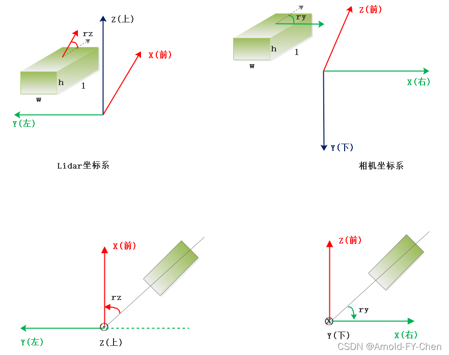
坐标系
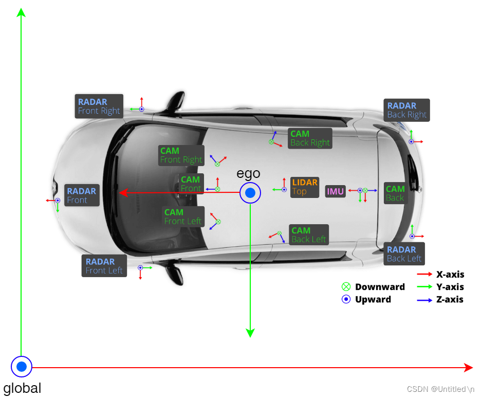
在自动驾驶的感知系统中,除了自车坐标系外,3D目标检测还涉及相机、激光雷达等传感器,每个传感器都有自己的坐标系。如下图
-
lidar坐标系
x轴向前,y轴向左,z轴向上。重力轴为z轴,参考方向为x轴正方向,航向角rz是lidar坐标系下目标的前进方向和x轴的夹角 -
camera坐标系
z轴向前,y轴向下,x轴向右。重力轴为y轴,参考方向为x轴正方向, 航向角ry是相机坐标下目标的前进方向和x轴的夹角
偏航角、观测角、目标方位角的关系
如下图,蓝色为ego vehicle,绿色为目标物体,相机坐标系的z轴向前.
-
方位角theta,定义为自车与目标物体连线偏离自车前进方向的角度
-
航向角rotation_y,即目标方向和相机X轴正方向的夹角(顺时针方向为正),描述的是目标在现实世界中的朝向。如图 ∠ B O C angle BOC ∠BOC所示。rotaiton_y的取值范围 [ − π , π ] [-pi, pi] [−π,π],不随目标位置的变化而变化,
-
观测角alpha, 描述的是目标相对于相机视角的朝向,定义为以相机原点为中心,相机原点到物体中心的连线为半径,将目标旋绕重力轴旋转到目标前进方向与ego vechicle一样时所需的角度,如图 ∠ B O D angle BOD ∠BOD所示。观测角alpha取值范围为 [ − π , π ] [-pi, pi] [−π,π],随目标位置变化而变化
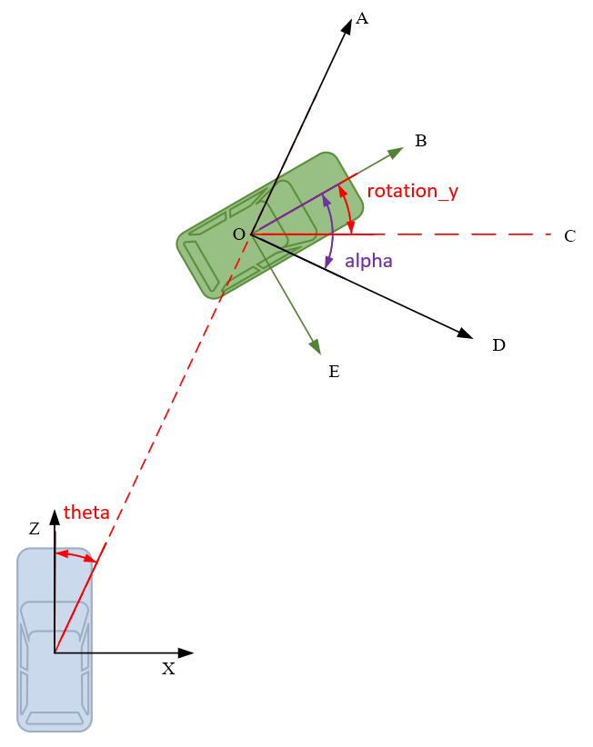
Rotation_y和Alpha之间可以相互转换。因为
∠
A
O
C
=
9
0
∘
−
theta
angle mathrm{AOC}=90^{circ}-text { theta }
∠AOC=90∘− theta ,所以有
∠
A
O
B
=
∠
A
O
C
−
∠
B
O
C
=
9
0
∘
−
theta
−
rotaion_y
angle mathrm{AOB}=angle mathrm{AOC}-angle mathrm{BOC}=90^{circ}-text { theta }-text { rotaion_y }
∠AOB=∠AOC−∠BOC=90∘− theta − rotaion_y
又因为
∠
A
O
B
+
∠
B
O
D
=
9
0
∘
angle mathrm{AOB} + angle mathrm{BOD} = 90^{circ}
∠AOB+∠BOD=90∘, 可得
alpha
=
∠
B
O
D
=
9
0
∘
−
∠
A
O
B
=
theta
+
rotation_y
text { alpha }=angle mathrm{BOD}=90^{circ}-angle mathrm{AOB}=text { theta }+text { rotation_y }
alpha =∠BOD=90∘−∠AOB= theta + rotation_y
考虑到rotation_y和alpha都是逆时针方向为负,所以有
−
alpha
=
theta
−
rotation_y
-text { alpha }=text { theta }-text { rotation_y }
− alpha = theta − rotation_y
即
alpha
=
rotation_y
−
theta
text { alpha }=text { rotation_y } - text { theta }
alpha = rotation_y − theta
数据集
NuScenes
点云数据原始格式
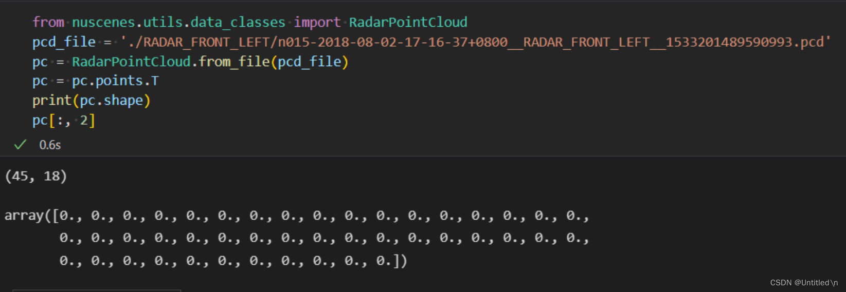
NuScenes数据中存在lidar点云和radar点云,其中lidar为稠密点云,具有三维坐标;而radar为稀疏点云,一般的FMCW毫米波雷达不存在高度信息(4D radar可以探测高度)。lidar点云数据的研究相对较多,这里不做过多介绍。
-
radar点云格式
radar的点云数据格式如下图所示,每一行为一个点,包含了点的坐标、速度、强度等信息。点云数据一般通过.pcd文件保存,包头等信息为明文,具体的点云数据为二进制数据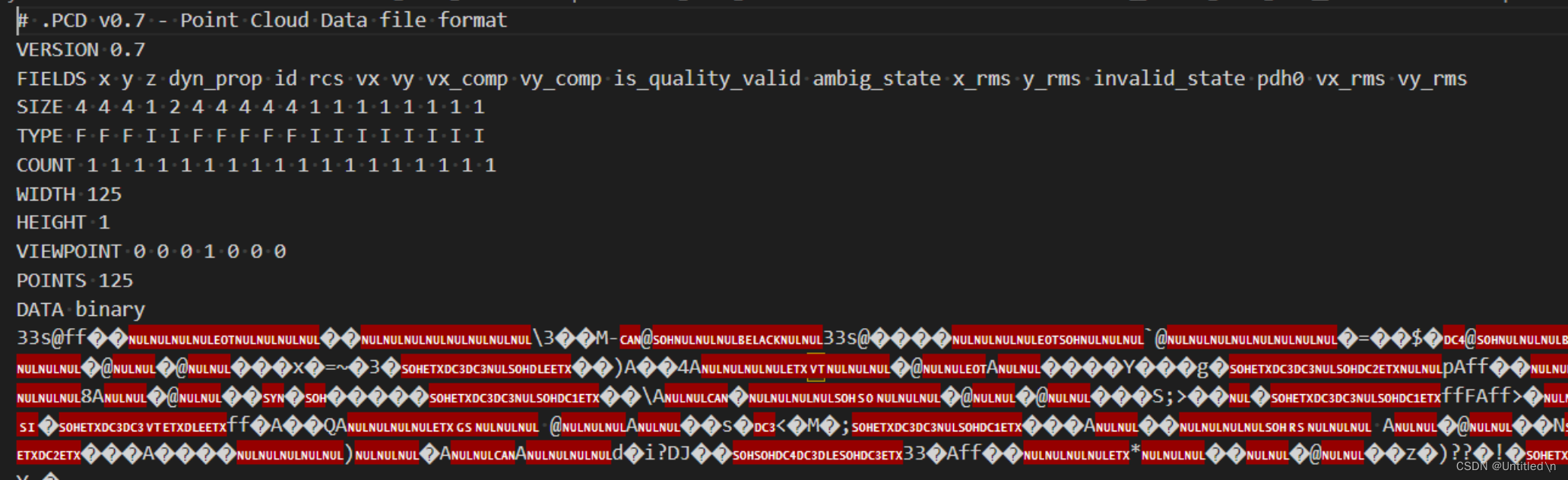
-
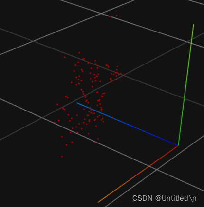
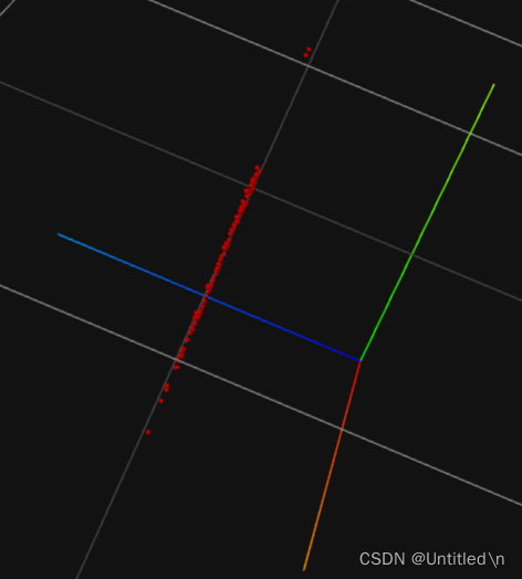
可视化效果
从不同的角度观察同一个pcd文件, 普通的毫米波雷达无法测量高度信息,因此右图中Z轴取值一样
-
验证高度数据
取值均为0
坐标转换
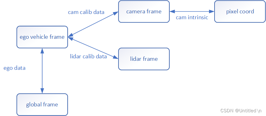
Nuscenes数据集分为全局坐标系、车身坐标系、camera坐标系、pixel坐标系、radar坐标系、lidar坐标系。除了全局坐标系,均为相对坐标系,标注真值基于全局坐标系。
基本原则
算法拟合的数据大多是基于出传感器坐标系,标注的真值需要从全局坐标系转换到各自的传感器坐标系,所有转换必须先通过传感器外参转到车身坐标系,再转换到传感器坐标系
如下,将全局坐标系下的标注box转化到传感器坐标系
 # Move box to ego vehicle coord system.
box.translate(-np.array(pose_record['translation']))
box.rotate(Quaternion(pose_record['rotation']).inverse)
#
Move box to sensor coord system.
box.translate(-np.array(cs_record['translation']))
box.rotate(Quaternion(cs_record['rotation']).inverse)
两个坐标系之间如何转换
通过两个坐标系下的坐标转换矩阵(平移矩阵+旋转矩阵)来转换,相机需要额外通过内参转换到pixel坐标系
def transform_matrix(translation: np.ndarray = np.array([0, 0, 0]),
rotation: Quaternion = Quaternion([1, 0, 0, 0]),
inverse: bool = False) -> np.ndarray:
"""
Convert pose to transformation matrix.
:param translation: <np.float32: 3>. Translation in x, y, z.
:param rotation: Rotation in quaternions (w ri rj rk).
:param inverse: Whether to compute inverse transform matrix.
:return: <np.float32: 4, 4>. Transformation matrix.
"""
tm = np.eye(4)
if inverse:
rot_inv = rotation.rotation_matrix.T
trans = np.transpose(-np.array(translation))
tm[:3, :3] = rot_inv
tm[:3, 3] = rot_inv.dot(trans)
else:
# rotation.rotation_matrix 表示将四元素 rotation 转换为旋转矩阵
# 并将旋转矩阵赋值给对角矩阵 tm 的前三行前三列
tm[:3, :3] = rotation.rotation_matrix
# 将矩阵 tm 的前三行第四列赋值为 translation
tm[:3, 3] = np.transpose(np.array(translation))
# 最后返回一个 4×4 的复合变换矩阵
return tm
以上返回的变换矩阵为复合变换矩阵, 包含位置(
translation)和旋转信息(rotation)两部分, 关于四元数、旋转矩阵、平移矩阵、复合变换矩阵的定义及关系,convert_nuScenes.py 文件代码详解中的三、main 函数部分有详细介绍
多传感器融合时的坐标转换
不同传感器采集频率不同,不是同步触发,一个传感器的数据需要投影到全局坐标系下,经过全局坐标系再投影到另一个传感器下达到时间对齐。借助于全局坐标系(绝对坐标系)进行运动补偿,从而完成了不同传感器之间的时间对齐。
- radar外参:radar坐标系到ego(车身)坐标系的复合变换矩阵,
- camera外参: camera坐标系到ego坐标系的复合变换矩阵
- ego_pose: ego坐标系到全局坐标系的复合变换矩阵
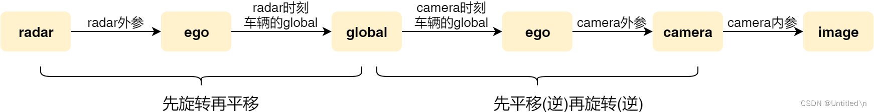
最后的通过矩阵乘法将点云投影到当前帧的坐标系下,从而完成时间对齐
# Fuse four transformation matrices into one and perform transform.
trans_matrix = reduce(np.dot, [ref_from_car, car_from_global, global_from_car, car_from_current])
velocity_trans_matrix = reduce(np.dot, [ref_from_car_rot, car_from_global_rot, global_from_car_rot, car_from_current_rot])
current_pc.transform(trans_matrix)
数据预处理
Kitti
REFERENCES
- 3D目标检测
- 点云数据
- 基于CenterTrack的3D目标检测源码解读
- 干货整理:欧拉角、旋转矩阵、四元数合辑
- 欧拉角pitch、yaw,roll的理解
- 旋转矩阵及左右乘的意义
- KITTI 3D目标检测数据集解析
- Nuscenes数据集中radar到image投影的源码解析
- NuScenes 3D目标检测数据集解析
- convert_nuScenes.py 文件代码详解
最后
以上就是重要酒窝最近收集整理的关于3D目标检测基础知识如何描述3D空间中的一个物体空间坐标变换坐标系偏航角、观测角、目标方位角的关系数据集REFERENCES的全部内容,更多相关3D目标检测基础知识如何描述3D空间中内容请搜索靠谱客的其他文章。


发表评论 取消回复