单片机课程设计:基于STM32智能交通灯的设计
文章目录
- 单片机课程设计:基于STM32智能交通灯的设计
- 前言
- 一、设计任务
- 二、系统硬件设计
- 1.元器件选用
- 2.系统模型设计
- 3.硬件连接
- 三、系统程序设计
- 1.程序流程
- 2.主程序
- 2.配置
- 总结
前言
生活中由于时间的影响相同道路不同时刻会有着不同车的流量,为了提高资源的利用,相同路段车流量小时如果交通灯时间等待过长,会造成当前时间段资源的浪费。如果该路段车流量较大而交通灯时间过短则会给予下一交通路段一定压力,严重时会导致交通混乱。为了防止此类情况的发生,设计一款智能交通信号灯以达到根据车流量的不同使得交通灯闪烁的时间不同来达到时空资源合理利用的目的。
一、设计任务
1、按键按下改变当前车流量。
2、OLED屏幕显示当前车流量、红绿黄灯的工作周期。
3、红绿黄灯根据当前车流量常亮指定时间。
二、系统硬件设计
基于STM32智能交通灯的设计系统是典型的嵌入式技术应用于测控系统,以嵌入式为开发平台,系统以32位单片机STM32为主控制器对各传感器数据进行采集,经过分析后去控制各执行设备。
1.元器件选用
1、输入输出控制电路(按键、发光二极管)。
2、STM32F103ZET6最小系统板1个。
3、3.6V电池3节。
4、电源管理模块1个。
5、稳压模块1个。
6、0.9寸OLED显示屏1个。
7、发光二极管3个。
8、按键3个。
9、导线若干根。
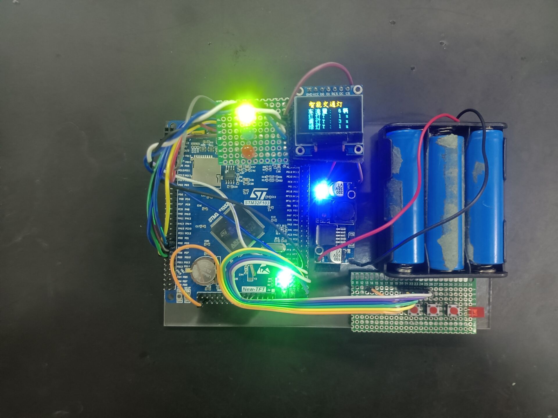
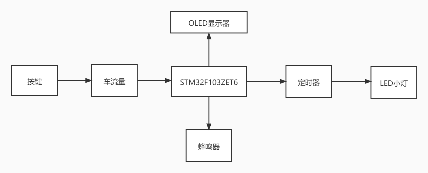
2.系统模型设计
模型无法实地检测车辆的数目故使用按键设置车流量的参数以达到模拟车流量的目的,同时,当前车流量会显示在OLED显示器上以便于观测。系统设置的算法根据当前车流量的不同进而控制信号灯的工作周期进行改变,以达到合理利用时空资源的目的。信号灯的工作周期也会实时显示在OLED显示器上。结构图如图所示。
3.硬件连接
按键连接STM32F103ZET6的PD2~PD7引脚,按键连接STM32的PE2、PE3、PE4引脚和GND,LED灯连接STM32的PF0、PF1、PF2引脚和GND,稳压连接单片机5V和GND引脚。
三、系统程序设计
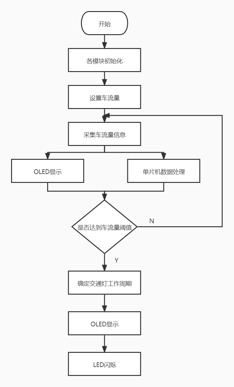
1.程序流程
车流量设置三个阈值,分别是低流量、中流量和高流量,分别对应三组小灯不同的工作周期,系统通过按键改变车流量阈值并在OLED显示屏上显示。单片机接收到按键值与预设的系统值作比较,如果当前车流量达到中流量,则定时器启动中流量时间,此时点亮小灯,当定时器定时结束,切换到另一盏小灯继续工作以模拟红绿灯的工作原理,此时中流量小灯工作的时间显示在OLED显示器上。程序流程图如图所示。
2.主程序
代码如下:
main.c
#include "system.h"
#include "SysTick.h"
#include "led.h"
#include "usart.h"
#include "oled.h"
#include "picture.h"
#include "key.h"
#include "time.h"
void bbb(void);
void led_con(void);
void show(void);
vu8 key=0;
u8 set_t=5;
int red=1,yellow=3,green=1;
int flag=0;
int red1=0,yellow1=0,green1=0;
int main()
{
u8 i=0;
SysTick_Init(72);
SysTick_Config(SystemCoreClock/100000);
NVIC_PriorityGroupConfig(NVIC_PriorityGroup_2);
//中断优先级分组 分2组
LED_Init();
OLED_Init(); //OLED初始化
KEY_Init();
TIM3_Int_Init(2000,36000-1);
//定时500ms(1000)
1s(2000)
show();
while(1)
{
key=KEY_Scan(0);	//得到键值

if(key == KEY_UP_PRESS){
//KEY1_PRES
bbb();
}
if(key == KEY0_PRESS){
//KEY2_PRES
set_t++;
if(set_t > 30){
set_t = 1;
}
led_con();
OLED_ShowNum(16*5,16,set_t,2,12);
OLED_ShowNum(16*5,28,red,2,12);
OLED_ShowNum(16*5,40,yellow,2,12);
OLED_ShowNum(16*5,52,green,2,12);
OLED_Refresh_Gram();
//刷新GRAM数组
}
if(key == KEY1_PRESS){
//KEY3_PRES
set_t--;
if(set_t <= 0){
set_t = 30;
}
led_con();
OLED_ShowNum(16*5,16,set_t,2,12);
OLED_ShowNum(16*5,28,red,2,12);
OLED_ShowNum(16*5,40,yellow,2,12);
OLED_ShowNum(16*5,52,green,2,12);
OLED_Refresh_Gram();
//刷新GRAM数组
}
}
}
//时间周期 3种模式
void TIM3_IRQHandler(void)
{
if(TIM_GetITStatus(TIM3,TIM_IT_Update))
{
///时间周期1/3/1
if(flag==1){
red1++;
if(red1==1){
LED3=1;
LED2=0;
LED1=0;
}
if(red1>=2&&red1<5){
LED3=0;
LED2=1;
LED1=0;
}
if(red1==5){
LED3=0;
LED2=0;
LED1=1;
}
if(red1==5){
red1=0;
}
}
///时间周期3/3/3
if(flag==2){
yellow1++;
if(yellow1>=1&&yellow1<4){
LED3=1;
LED2=0;
LED1=0;
}
if(yellow1>=4&&yellow1<7){
LED3=0;
LED2=1;
LED1=0;
}
if(yellow1>=7&&yellow1<=9){
LED3=0;
LED2=0;
LED1=1;
}
if(yellow1==9){
yellow1=0;
}
}
///时间周期5/3/5
if(flag==3){
green1++;
if(green1>=1&&green1<6){
LED3=1;
LED2=0;
LED1=0;
}
if(green1>=6&&green1<9){
LED3=0;
LED2=1;
LED1=0;
}
if(green1>=9&&green1<=13){
LED3=0;
LED2=0;
LED1=1;
}
if(green1==13){
green1=0;
}
}
}
TIM_ClearITPendingBit(TIM3,TIM_IT_Update);
}
//主界面中红黄绿灯工作周期参数显示
void led_con()
{
if(set_t>=0&&set_t<10){
red = 1;
yellow = 3;
green = 1;
flag=1;
}
if(set_t>=10&&set_t<20){
red = 3;
yellow = 3;
green = 3;
flag=2;
}
if(set_t>=20&&set_t<=30){
red = 5;
yellow = 3;
green = 5;
flag=3;
}
}
//最开始显示“欢迎”的界面,按下任意按键后进入主界面
void show()
{
OLED_ShowFontHZ(16*3,0,15,16,1);
OLED_ShowFontHZ(16*4,0,16,16,1);
OLED_Refresh_Gram();
//刷新GRAM数组
}
//字符显示界面(主界面)
void bbb()
{
OLED_ShowFontHZ(16*1,0,0,16,1);//智能交通灯
OLED_ShowFontHZ(16*2,0,1,16,1);
OLED_ShowFontHZ(16*3,0,2,16,1);
OLED_ShowFontHZ(16*4,0,3,16,1);
OLED_ShowFontHZ(16*5,0,4,16,1);
OLED_ShowFontHZ(16*1,16,7,12,1);//车流量
OLED_ShowFontHZ(16*2,16,8,12,1);
OLED_ShowFontHZ(16*3,16,9,12,1);
OLED_ShowString(16*4,16,":",12);
OLED_ShowNum(16*5,16,set_t,2,12);
OLED_ShowFontHZ(16*6,16,13,12,1);
OLED_ShowFontHZ(16*1,28,10,12,1);//红灯
OLED_ShowFontHZ(16*2,28,14,12,1);
OLED_ShowString(16*3,28,"T",12);
OLED_ShowString(16*4,28,":",12);
OLED_ShowNum(16*5,28,red,2,12);
OLED_ShowString(16*6,28," s",12);
OLED_ShowFontHZ(16*1,40,11,12,1);//黄灯
OLED_ShowFontHZ(16*2,40,14,12,1);
OLED_ShowString(16*3,40,"T",12);
OLED_ShowString(16*4,40,":",12);
OLED_ShowNum(16*5,40,yellow,2,12);
OLED_ShowString(16*6,40," s",12);
OLED_ShowFontHZ(16*1,52,12,12,1);//绿灯
OLED_ShowFontHZ(16*2,52,14,12,1);
OLED_ShowString(16*3,52,"T",12);
OLED_ShowString(16*4,52,":",12);
OLED_ShowNum(16*5,52,green,2,12);
OLED_ShowString(16*6,52," s",12);
OLED_Refresh_Gram();
//刷新GRAM数组
}
2.配置
led.c
#include "led.h"
void LED_Init(void)
{
GPIO_InitTypeDef GPIO_InitStructure;//定义结构体变量
RCC_APB2PeriphClockCmd(LED1_PORT_RCC|LED2_PORT_RCC|LED3_PORT_RCC,ENABLE);
GPIO_InitStructure.GPIO_Pin=LED1_PIN;
//选择你要设置的IO口
GPIO_InitStructure.GPIO_Mode=GPIO_Mode_Out_PP;
//设置推挽输出模式
GPIO_InitStructure.GPIO_Speed=GPIO_Speed_50MHz;
//设置传输速率
GPIO_Init(LED1_PORT,&GPIO_InitStructure);
/* 初始化GPIO */
GPIO_SetBits(LED1_PORT,LED1_PIN);
//将LED端口拉高,熄灭所有LED
GPIO_InitStructure.GPIO_Pin=LED2_PIN;
//选择你要设置的IO口
GPIO_Init(LED2_PORT,&GPIO_InitStructure);
/* 初始化GPIO */
GPIO_SetBits(LED2_PORT,LED2_PIN);
//将LED端口拉高,熄灭所有LED
GPIO_InitStructure.GPIO_Pin=LED3_PIN;
//选择你要设置的IO口
GPIO_Init(LED3_PORT,&GPIO_InitStructure);
/* 初始化GPIO */
GPIO_SetBits(LED3_PORT,LED3_PIN);
//将LED端口拉高,熄灭所有LED
}
led.h
#ifndef _led_H
#define _led_H
#include "system.h"
/*
LED时钟端口、引脚定义 */
#define LED1_PORT
GPIOF
#define LED1_PIN
GPIO_Pin_2
#define LED1_PORT_RCC
RCC_APB2Periph_GPIOF
#define LED2_PORT
GPIOF

#define LED2_PIN
GPIO_Pin_1
#define LED2_PORT_RCC
RCC_APB2Periph_GPIOF
#define LED3_PORT
GPIOF

#define LED3_PIN
GPIO_Pin_0
#define LED3_PORT_RCC
RCC_APB2Periph_GPIOF
#define LED1 PFout(2)

#define LED2 PFout(1)

#define LED3 PFout(0)
void LED_Init(void);
#endif
key.c
#include "stm32f10x.h"
#include "key.h"
#include "SysTick.h"
//按键初始化函数
void KEY_Init(void) //IO初始化
{
GPIO_InitTypeDef GPIO_InitStructure;
RCC_APB2PeriphClockCmd(RCC_APB2Periph_GPIOA|RCC_APB2Periph_GPIOE,ENABLE);//使能PORTA,PORTE时钟
GPIO_InitStructure.GPIO_Pin
= GPIO_Pin_4|GPIO_Pin_3|GPIO_Pin_2|GPIO_Pin_1|GPIO_Pin_6;;//KEY0-KEY1
GPIO_InitStructure.GPIO_Mode = GPIO_Mode_IPU; //设置成上拉输入
GPIO_Init(GPIOE, &GPIO_InitStructure);//初始化GPIOE4,3
//初始化 WK_UP-->GPIOA.0
下拉输入
GPIO_InitStructure.GPIO_Pin
= GPIO_Pin_0;
GPIO_InitStructure.GPIO_Mode = GPIO_Mode_IPD; //PA0设置成输入,默认下拉

GPIO_Init(GPIOA, &GPIO_InitStructure);//初始化GPIOA.0
}
u8 KEY_Scan(u8 mode)
{
static u8 key=1;
if(mode==1) //连续按键按下
key=1;
if(key==1&&(KEY_UP==1||KEY0==0||KEY1==0)) //任意一个按键按下
{
delay_ms(10);
//消抖
key=0;
if(KEY_UP==1)
return KEY_UP_PRESS;
else if(KEY0==0)
return KEY0_PRESS;
else if(KEY1==0)
return KEY1_PRESS;
}
else if(KEY_UP==0&&KEY0==1&&KEY1==1)
//无按键按下
key=1;
return 0;
}
key.h
#ifndef __KEY_H
#define __KEY_H

#include "SysTick.h"
#define KEY0_PIN
GPIO_Pin_4
//定义KEY0管脚
#define KEY1_PIN
GPIO_Pin_3
//定义KEY1管脚
#define KEY_UP_PIN
GPIO_Pin_0
//定义KEY_UP管脚
#define KEY_PORT
GPIOE
//定义端口
#define KEY_UP_PORT
GPIOA
//定义端口
//使用位操作定义
#define KEY_UP
PAin(0)
#define KEY0
PEin(4)
#define KEY1
PEin(3)
//定义各个按键值

#define KEY_UP_PRESS
1
#define KEY0_PRESS
2
#define KEY1_PRESS
3
void KEY_Init(void);//IO初始化
u8 KEY_Scan(u8);
//按键扫描函数

#endif
总结
基于STM32智能交通灯是一个简单的stm32设计,交通灯的设计包含了GPIO的配置、OLED屏幕的使用、按键操作、中断的运用,适合stm32初学者在学习理论知识和例程之后对知识的融会贯通与应用。
高度概括了学习stm32从点灯到点灯的理念(不是 QvQ)。
下载地址:
https://download.csdn.net/download/qq_50185399/86774900?spm=1001.2014.3001.5503
最后
以上就是刻苦外套最近收集整理的关于单片机课程设计:基于STM32智能交通灯的设计前言一、设计任务二、系统硬件设计三、系统程序设计总结的全部内容,更多相关单片机课程设计:基于STM32智能交通灯内容请搜索靠谱客的其他文章。


![MATLAB交通信号灯识别[完美运行,详细解释,GUI界面,万字文稿]](https://www.shuijiaxian.com/files_image/reation/bcimg24.png)

发表评论 取消回复