原视频来自:
https://ww2.mathworks.cn/en/videos/5g-explained-downlink-control-information-in-5g-nr-1559889840642.html。
文中顺序依次是视频、中文译文和英文原文。
中文:
这是我们“ 5G解释” 系列的新内容。 在此视频中,我们将讨论5G NR的下行链路控制信息(Downlink Control Information)。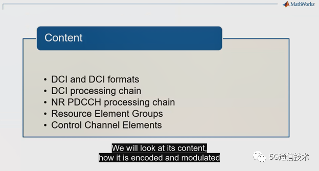
我们将研究DCI是怎样编码和调制,然后通过物理下行链路控制信道(PDCCH)将其映射到5G NR的时隙。 在此,我们还将介绍资源单元组和控制信道单元的概念。
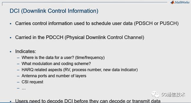
下行链路控制信息(DCI)承载用于调度用户数据的控制信息。下行链路共享信道(PDSCH)和上行链路共享信道(PUSCH)的调度信息都是由PDCCH承载。 它指示调度传输的数据在时间和频率上的位置、使用的调制方式和编码方案、天线端口或天线层数以及其他方面(例如HARQ)。用户设备需要先解码DCI,然后才能解码下行链路数据或发送上行链路数据。
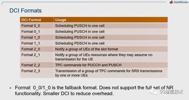
根据DCI的内容,可以使用几种格式中的一种或多种。 格式0用于上行链路授权,这意味着它包含与UE即将在上行链路上传输的数据有关的信息。 格式1用于下行链路分配, 这意味着它包含有关数据发送到UE的方式的信息。如上一张幻灯片所述,对于上行链路信息和下行链路信息,都有两种可能的格式:一种下划线为0,另一种为下划线1。下划线为0的格式称为后备格式。 它比带有下划线1的完整格式更紧凑,因为它不包括所有选项,因此,它在减少调度灵活性与降低控制开销之间进行了权衡。 最后,格式2的调度信息则用于发送数据给一组UE和发送TPC命令组。
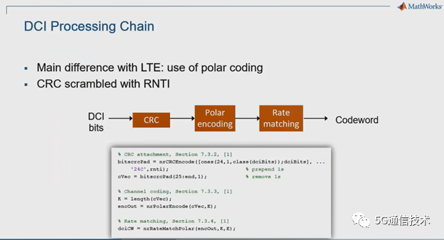
下行链路控制信息使用POLAR码进行容错保护,而LTE是使用咬尾卷积码,这是NR与LTE的主要区别。 与LTE的另一个区别是,这里使用的CRC更长,为24位,而不是LTE的16位。 CRC加扰使用UE RNTI,以指示消息是发送给哪个UE的。 您可以看到MathWorks 5G Toolbox如何通过几行MATLAB代码来简洁地描述该处理链。
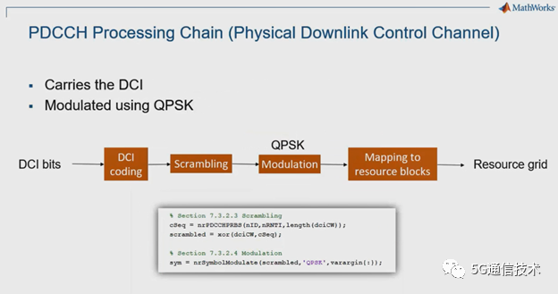
编码后,还要对下行链路控制信息进行加扰和QPSK调制,并以非常特定的模式映射到资源块。 我们将在接下来的几张幻灯片以及“ 5G Explained”系列的另一集中更详细地说明这种映射。这里,您可以看到MathWorks 5GToolbox用几行代码就可以实现对PDCCH处理过程进行建模。
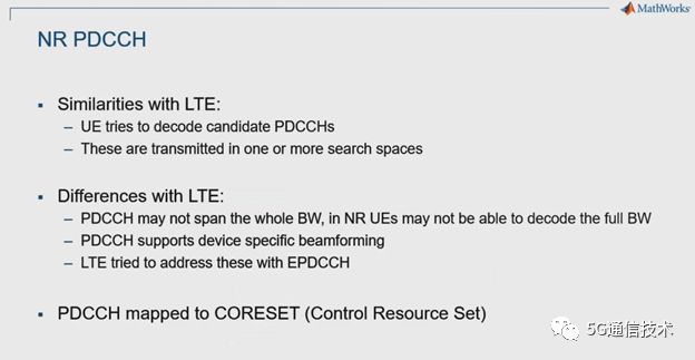
与LTE中一样,UE必须寻找并解码PDCCH,标准规定了几种可能的候选搜索空间和配置。但是与LTE相比有一些重大差异,其中的一些差异将在“ 5G解释”系列的另一集中进行详细说明。首先,PDCCH可能不会分布在整个5G带宽上,这与LTE不同。这一点很重要,因为5G带宽更大,可高达400MHz,5G的UE并不需要支持那么大的带宽。这为在5G中使用更简单、更便宜的终端设备打开了大门。其次,5G中的PDCCH支持设备关联的波束成形。这意味着gNB可以向特定UE发送控制信息。这是可能的,因为PDCCH具有关联的解调参考符号(DMRS),它们使用相同的波束成形。这类似于LTE部署后期引入的EPDCCH的概念。请注意,PDCCH被映射到CORESET(控制资源集),CORESET定义了5G资源网格内控制区域的位置,并会在“5G解释”系列的另一集中说明。
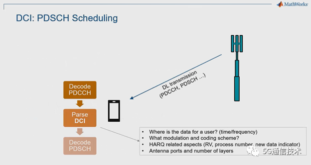
现在让我们看一下DCI使用的两个具体示例,第一个用于下行链路数据调度。 UE在公共搜索空间上查找PDCCH,如果找到匹配项,则UE将解析DCI,并提取UE数据位于时间和频率的位置。利用DCI信息,UE可以获取数据在5G网格资源中对应的位置,并执行信道估计、均衡、逆速率匹配和解码,收取下行链路数据。
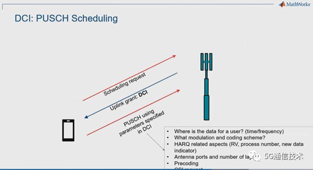
对于上行链路传输,携带上行链路许可的DCI是为了响应来自UE的调度请求。 当gNB接收到调度请求时,它会规定UE应该何时以及如何发送上行数据。 这些控制参数包括时间和频率位置、调制和编码方案和其他信息,例如预编码。在“ 5G解释”系列的另一集中,会解释DCI控制信息中有关UE如何发送sounding的信息。 UE解码控制信息后(请记住,格式为0_0或0_1),UE根据这些参数发送上行数据。
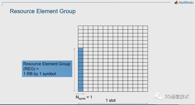
要了解如何将下行链路信息映射到5G网格,我们必须引入两个新概念:资源单元组和控制信道单元(CCE)。 资源单元组(REG)在时域上对应一个符号,在频域上对应12个资源单元,这是定义CCE的基本单位。
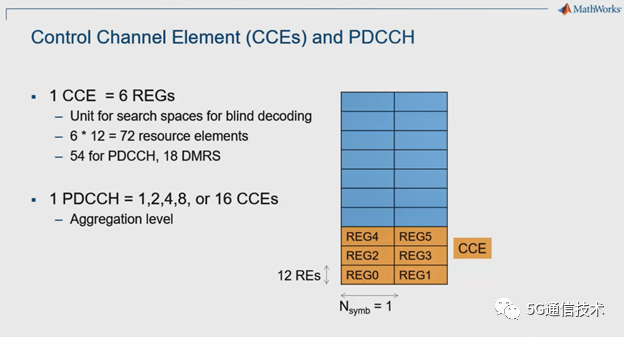
一个CCE(控制信道单元)对应6个REG(资源单元组)。这意味着一个CCE包含 6x12= 72个资源单元。其中54个可用于PDCCH本身,18个留给相关的DMRS(解调参考符号)信号,用于UE执行信道估计,这主要考虑了包括波束成形等技术对传播信道的影响。最后,一个PDCCH可以被映射到一个或多个CCE。5G NR 标准定义了与LTE中相同的几种聚合级别,聚合等级16是NR新引入的, LTE不支持。显然,聚合级别越高,可使用的资源越多,但是冗余的可能性就越大,因此支持的小区覆盖范围就越大。此处的配置显示的CCE使用3x2个资源单元组,实际配置可能有所不同,例如6x1或2x3。我们将在有关CORESET的“5G解释”系列的另一集中介绍更多细节。有关下行链路控制传输的内容到此结束。
英文:
This is a new episode of our series, "5G Explained." In this video, we discuss downlink control information or DCI in 5G New Radio.
We will look at its content, how it is encoded and modulated, then mapped to the 5G New Radio slot via the PDCCH or physical downlink control channel. In the process, we will introduce the concepts of resource element groups and control channel elements.
Downlink control information, or DCI, carries control information used to schedule user data, PDSCH on the downlink and PUSCH on theuplink. It is carried by the PDCCH or physical downlink control channel. It indicates the location in time and frequency of the data that is scheduled for transmission, the modulation and coding schemes used, the number of antenna ports or layers, as well as other aspects such as HARQ. The user equipment needs to decode the DCI before they can decode downlink data or transmit uplinkdata.
Depending on the content of a DCI, one or more of several formats can be used. Format 0 is for uplink grant, meaning that it contains information that pertains to datathe UE is about to transmit on the uplink. Format 1 is for downlink allocation.This means it includes information about the way data was sent to the UE as discussed on the previous slide.
For both uplink and downlink information, there are two possible formats: one with underscore 0 and one with underscore 1. The format with underscores 0 is called the fallback format. It is more compact than the full format with underscore 1 because it doesn't include all options and, therefore, it trades off less scheduling flexibility for reduced control overhead. Finally, format 2 address information needed for groups of UEs and TPC commands.
Downlink control information uses polar code for error protection. This is the main difference with encoding in LTE where tail-biting convolutional encoding was used. Another difference with LTE is that the CRC used here is longer at 24 bits instead of 16 for LTE. The CRC value is scrambled with a UE identifier called the radio network temporary identifier or RNTI in order to indicate which UE the message is intended for. You can see how MathWorks 5G Toolbox lets you succinctly describe this processing chain with a few lines of MATLAB code.
After encoding, downlink control information is scrambled, QPSK modulated, and mapped to resource blocks with a very specific pattern. We will explain this mappingin more detail in the next few slides as well as in another episode of this"5G Explained" series about core sets. Here again, you can see how MathWorks 5G Toolbox models the PDCCH processing chain with a few lines of code.
As in LTE, the UE must look for and decode the PDCCH, and there are several possible candidate search spaces and configurations. But there are several significant differences with LTE, some of which will be explained in much more detail in another episode of this "5G Explained" series. First, the PDCCH may not span the complete 5G bandwidth, whereas in LTE it always does.This is important because the bandwidth may be much larger, up to 400 megahertz in 5G, and UEs in 5G are not required to support a large bandwidth, opening the door to simpler, cheaper devices.
Second, PDCCH in 5G supports device specific beamforming. This means control information can be beamed toward a particular UE. This is possible because a PDCCH has associated DMRS, or demodulation reference symbols, which undergo the same beamforming. It is similar to the concept of EPDCCH that was introduced late in LTE deployment. Note that PDCCH is mapped to a CORESET or control resource set, a concept that defines the location of acontrol region within the 5G resource grid and is the object of another episodeof this "5G Explained" series.
Let us now look at two concrete examples of DCI usage, first for downlink data scheduling. The UE looks for the PDCCH, and if a match is found, meaning that a block decoded with a CRC that matches the RNTI of the UE, it parses the DCI and extracts all information about where in time and frequency the data is located and how data was sent to the UE. With this information, the UE can grab the relevant parts of the 5G grid, perform channel estimation, equalization,inverse rate matching, and decoding to retrieve the downlink data packet.
For uplink transmission, downlink control information carrying an uplink grant comes in response to a scheduling request from the UE. When the receives the scheduling request, it makes all the decisions about when and how the UE should transmit the data that is ready for transmission. Those parameters include--besides the time and frequency, location, and modulation and coding scheme--other information such as precoding, which comes in the form of an index that points to a table of possible precoding matrices.
There is more information about this scheme in another episode of this "5G Explained" series about channel sounding. After decoding the control information for the uplink grant--remember, this would be format 0_0 or 0_1--the UE transmits uplink data according to those parameters.
To understand how downlink information is mapped to the 5G grid, we must introduce two new concepts: resource element groups and control channel elements or CCEs.A resource element group is simply a block of 12 resource elements by one symbol. This is the basic unit used to define CCEs.
One control channel element corresponds to six resource element groups. This means that once CCE includes 6 times 12 equals 72 resource elements. Of those, 54 areavailable for the PDCCH itself, and 18 are reserved for associated DMRS or demodulation reference symbols, which let the UE perform channel estimation,which is account for propagation channel effects including beamforming.
Finally, one PDCCH is mapped to one or more CCEs. The standard defines several aggregation levels as in LTE, except for the introduction of anew level of 16, which was not available in LTE. Clearly, the higher the aggregation level, the more resources are used, but the more possibility for redundancy and, hence, increase range.
Note that the configuration here shows a grid of three by two resource element groups for one CCE, but the actual configuration could be different, for example, six by one, or two by three. We will show more detail in another episode of this "5G Explained" series about CORESETs. This concludes this episode of the"5G Explained" series on downlink control transmission.
文章来源:5G通信技术
最后
以上就是平常泥猴桃最近收集整理的关于ls信道估计matlab_5G NR 下行链路控制信道(内含5G英文视频)的全部内容,更多相关ls信道估计matlab_5G内容请搜索靠谱客的其他文章。


发表评论 取消回复