本文基于FPGA实现了ARP和UDP传输协议。
开发环境:Win7
开发软件:Quartus17.1、Modelsim SE-64 10.2c、Gvim编辑器、小兵以太网测试仪、Wireshark
开发硬件:小梅哥AC6102_V2开发板
注意:本工程都假设FPGA设备IP地址为192.168.0.2(即0xc0_a8_00_02),MAC地址为0x00_0a_35_01_fe_c0,PC端IP地址为192.168.0.3(即0xc0_a8_00_03)
1 以太网原理介绍
1.1 以太网帧
在以太网链路上的数据包称作以太网帧。以太网帧起始部分由前导码和帧开始符组成。后面紧跟着一个以太网报头,以MAC地址说明目的地址和源地址。帧的中部是该帧负载的包含其他协议报头的数据包(例如IP协议、ARP协议)。以太帧由一个32位冗余校验码结尾。它用于检验数据传输是否出现损坏。以太网帧格式如下图所示。
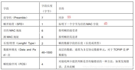
1.前导码和帧开始符是固定的,为7个0x55紧跟着1个0xd5
2.目的MAC地址指明帧的接受者
3.源MAC地址指明帧的发送者
4.以太网类型,指示帧的类型,比如0x0800表示该帧是IP数据包,0x0806表示该帧是ARP协议数据包
5.数据和填充就是所承载的数据包,跟前面以太网类型对应。
6.帧校验序列是一个32位的循环校验码(FCS)。
每一个设备都有一个不同的MAC地址,当一个设备A发送一个以太网帧,源MAC地址是自己的MAC地址,目的MAC地址如果是0xffffff,此时就是广播,所有与之连接的设备都会收到该帧,如果目的MAC地址是一个独特的MAC地址,那么本地MAC地址与之相同的设备将会接收到该以太网帧,然后通过判断以太网帧类型,进行下一步数据包解析。
1.2 ARP协议
ARP协议,全称为Address Resolution Protocol,即地址解析协议,ARP协议属于以太网帧的一种,前面以太网帧介绍中有说到,我们如果从设备A发送以太网帧到设备B,我们不可能每次都进行广播,那么设备A如何知道设备B的物理地址呢?ARP协议就是为了解决这个问题。
首先设备A广播,发送ARP请求,等收到设备B的ARP应答以后就能知道设备B的MAC地址。ARP帧格式如下图所示
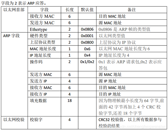
ARP字段就是前面以太网帧待填充的数据。
硬件类型、上层协议类型、MAC地址长度、IP地址长度均固定不变。
假设设备A的IP地址为192.168.0.2,MAC地址为0x00_0a_35_01_fe_c0,我们知道目的IP地址为192.168.0.3,不知道该IP地址对应的MAC地址,如果设备A想要和IP地址为192.168.0.3的设备B进行通信(如UDP或者IP通信),就必须知道它的MAC地址。此时设备A就需要广播发送ARP请求,接收方MAC地址填0xff_ff_ff_ff_ff_ff。这样IP地址为192.168.0.3的设备就会解析出这是一个ARP请求,它询问自身的MAC地址,此时它就会做出ARP应答,将自身的MAC地址发送给对应IP地址的设备A。
注意发送ARP请求时,操作码为0x0001,应答时操作码为0x0002。
1.3 IP协议
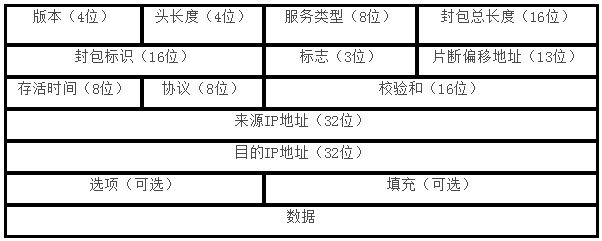
TCP/IP协议定义了一个在因特网上传输的包,称为IP数据包,而IP数据报(IP Datagram)是个比较抽象的内容,是对数据包的结构进行分析。 由首部和数据两部分组成,其格式如下图图所示。首部的前一部分是固定长度,共20字节,是所有IP数据报必须具有的。在首部的固定部分的后面是一些可选字段,其长度是可变的。首部中的源地址和目的地址都是IP协议地址。
1.4 UDP协议
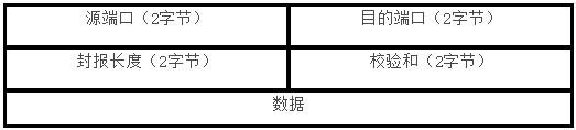
UDP 协议是一种不可靠传输,发送方只负责将数据发送出去,而不管接收方是否正确的接收。 非常类似于 UART 串口传输。 但是,在很多场合,是可以接受这种潜在的不可靠性的,例如视频实时传输显示。 在这类系统中,由于数据并不需要进行运算并得到非常精确的结果用于其他功能,而仅仅是显示在屏幕上,因此可以接受一定程度的丢包或者误码。此类应用在 LED 大屏显示系统中应用非常广泛。UDP帧组成如下图所示
2 GMII接口介绍
在芯航线 AC6102 开发板上,设计了一路 GMII 接口的千兆以太网电路,通过该以太网电路,用户可以将 FPGA 采集或运算得到的数据传递给其他设备如 PC 或服务器,或者接收其他设备传输过来的数据并进行处理。首先介绍一下GMII接口。
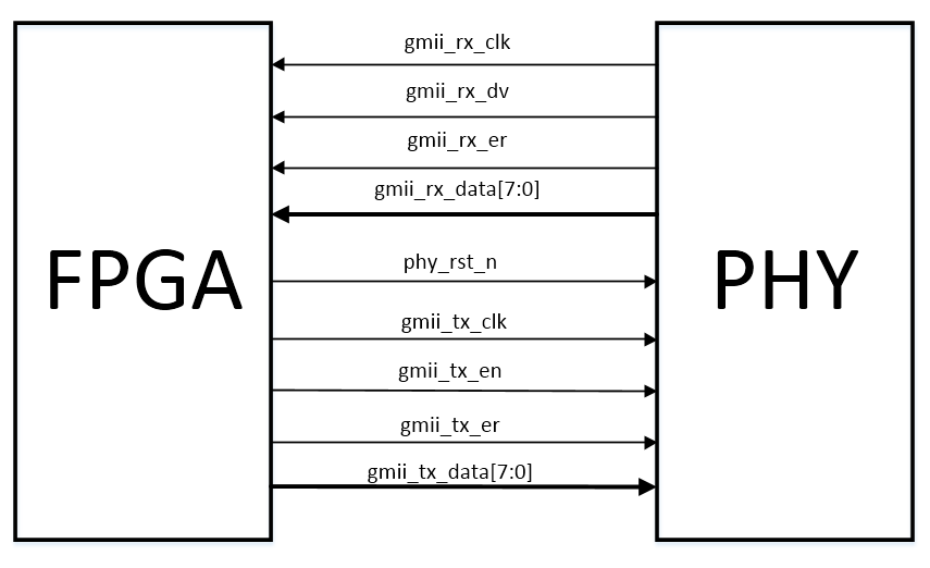
gmii_rx_clk是PHY发送过来的时钟,FPGA通过该时钟进行采样
gmii_rx_dv是接收数据有效标志,与gmii_rx_data对齐
gmii_rx_er是错误标志,当它有效时,说明发送帧错误
gmii_rx_data是PHY发送过来的数据
phy_rst_n是低电平复位信号
gmii_tx_clk是FPGA发送时钟,这里直接使用gmii_rx_clk即可
gmii_tx_en发送数据有效标志,与gmii_tx_data对齐
gmii_tx_er是错误标志
gmii_tx_data是FPGA发送给PHY的数据
以上就是GMII接口所有的信号。
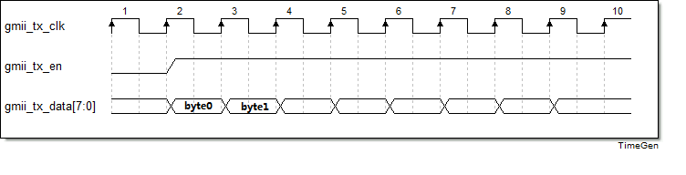
在发送数据时,只需要按以下时序发送。
3 ARP协议实现
在本工程中,ARP实现分两部分,一是由FPGA发送ARP请求,二是对发送过来的ARP应答进行解析,得到目的IP地址对应的MAC地址。
这样我们就可以知道,发送ARP请求完整的帧内容了。如下图所示。(数据格式为16进制)
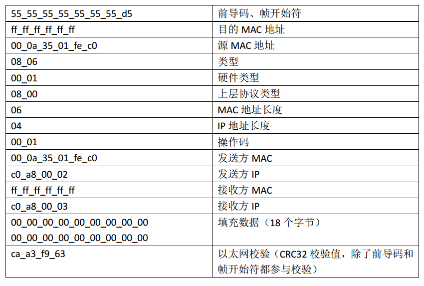
除了CRC32校验值之外,其他都是固定的,CRC32需要进行计算。关于CRC32的8位并行计算,大家可以参考下面这篇论文。千兆以太网MAC中CRC算法的设计与实现
用CRC计算软件可以算出,也可以用FPGA实现。
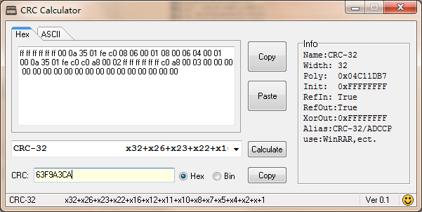
由计算软件看出crc32校验结果为0x63f9a3ca,在发送时,按7-0、15-8、23-16、31-24的顺序发送。
下面给出CRC32的FPGA实现代码:
module  crc(
    input                       clk                             ,
    input                       rst_n                           ,
    input         [ 7: 0]       din                             ,
    input                       crc_en                          ,
    input                       crc_init                        ,
    output  reg   [31: 0]       crc
);
//======================================================================
//************** Define Parameter and Internal Signals *****************
//======================================================================/
wire    [ 7: 0]                 data                            ;
wire    [31: 0]                 crc_next                        ;
//======================================================================
//**************************** Main Code *******************************
//======================================================================/
assign data={din[0],din[1],din[2],din[3],din[4],din[5],din[6],din[7]};

assign crc_next[0]  = crc[24] ^ crc[30] ^ data[0] ^ data[6];
assign crc_next[1]  = crc[24] ^ crc[25] ^ crc[30] ^ crc[31] ^ data[0] ^ data[1] ^ data[6] ^ data[7];
assign crc_next[2]  = crc[24] ^ crc[25] ^ crc[26] ^ crc[30] ^ crc[31] ^ data[0] ^ data[1] ^ data[2] ^ data[6] ^ data[7];
assign crc_next[3]  = crc[25] ^ crc[26] ^ crc[27] ^ crc[31] ^ data[1] ^ data[2] ^ data[3] ^ data[7];
assign crc_next[4]  = crc[24] ^ crc[26] ^ crc[27] ^ crc[28] ^ crc[30] ^ data[0] ^ data[2] ^ data[3] ^ data[4] ^ data[6];
assign crc_next[5]  = crc[24] ^ crc[25] ^ crc[27] ^ crc[28] ^ crc[29] ^ crc[30] ^ crc[31] ^ data[0] ^ data[1] ^ data[3] ^ data[4] ^ data[5] ^ data[6] ^ data[7];
assign crc_next[6]  = crc[25] ^ crc[26] ^ crc[28] ^ crc[29] ^ crc[30] ^ crc[31] ^ data[1] ^ data[2] ^ data[4] ^ data[5] ^ data[6] ^ data[7];
assign crc_next[7]  = crc[24] ^ crc[26] ^ crc[27] ^ crc[29] ^ crc[31] ^ data[0] ^ data[2] ^ data[3] ^ data[5] ^ data[7];
assign crc_next[8]  = crc[0]  ^ crc[24] ^ crc[25] ^ crc[27] ^ crc[28] ^ data[0] ^ data[1] ^ data[3] ^ data[4];
assign crc_next[9]  = crc[1]  ^ crc[25] ^ crc[26] ^ crc[28] ^ crc[29] ^ data[1] ^ data[2] ^ data[4] ^ data[5];
assign crc_next[10] = crc[2]  ^ crc[24] ^ crc[26] ^ crc[27] ^ crc[29] ^ data[0] ^ data[2] ^ data[3] ^ data[5];
assign crc_next[11] = crc[3]  ^ crc[24] ^ crc[25] ^ crc[27] ^ crc[28] ^ data[0] ^ data[1] ^ data[3] ^ data[4];
assign crc_next[12] = crc[4]  ^ crc[24] ^ crc[25] ^ crc[26] ^ crc[28] ^ crc[29] ^ crc[30] ^ data[0] ^ data[1] ^ data[2] ^ data[4] ^ data[5] ^ data[6];
assign crc_next[13] = crc[5]  ^ crc[25] ^ crc[26] ^ crc[27] ^ crc[29] ^ crc[30] ^ crc[31] ^ data[1] ^ data[2] ^ data[3] ^ data[5] ^ data[6] ^ data[7];
assign crc_next[14] = crc[6]  ^ crc[26] ^ crc[27] ^ crc[28] ^ crc[30] ^ crc[31] ^ data[2] ^ data[3] ^ data[4] ^ data[6] ^ data[7];
assign crc_next[15] = crc[7]  ^ crc[27] ^ crc[28] ^ crc[29] ^ crc[31] ^ data[3] ^ data[4] ^ data[5] ^ data[7];
assign crc_next[16] = crc[8]  ^ crc[24] ^ crc[28] ^ crc[29] ^ data[0] ^ data[4] ^ data[5];
assign crc_next[17] = crc[9]  ^ crc[25] ^ crc[29] ^ crc[30] ^ data[1] ^ data[5] ^ data[6];
assign crc_next[18] = crc[10] ^ crc[26] ^ crc[30] ^ crc[31] ^ data[2] ^ data[6] ^ data[7];
assign crc_next[19] = crc[11] ^ crc[27] ^ crc[31] ^ data[3] ^ data[7];
assign crc_next[20] = crc[12] ^ crc[28] ^ data[4];
assign crc_next[21] = crc[13] ^ crc[29] ^ data[5];
assign crc_next[22] = crc[14] ^ crc[24] ^ data[0];
assign crc_next[23] = crc[15] ^ crc[24] ^ crc[25] ^ crc[30] ^ data[0] ^ data[1] ^ data[6];
assign crc_next[24] = crc[16] ^ crc[25] ^ crc[26] ^ crc[31] ^ data[1] ^ data[2] ^ data[7];
assign crc_next[25] = crc[17] ^ crc[26] ^ crc[27] ^ data[2] ^ data[3];
assign crc_next[26] = crc[18] ^ crc[24] ^ crc[27] ^ crc[28] ^ crc[30] ^ data[0] ^ data[3] ^ data[4] ^ data[6];
assign crc_next[27] = crc[19] ^ crc[25] ^ crc[28] ^ crc[29] ^ crc[31] ^ data[1] ^ data[4] ^ data[5] ^ data[7];
assign crc_next[28] = crc[20] ^ crc[26] ^ crc[29] ^ crc[30] ^ data[2] ^ data[5] ^ data[6];
assign crc_next[29] = crc[21] ^ crc[27] ^ crc[30] ^ crc[31] ^ data[3] ^ data[6] ^ data[7];
assign crc_next[30] = crc[22] ^ crc[28] ^ crc[31] ^ data[4] ^ data[7];
assign crc_next[31] = crc[23] ^ crc[29] ^ data[5];

//crc 这里用下降沿采集,是为了crc能提前半拍送到eth_mac_send模块中,这个很重要
//否则crc高8位会发送出错,自己可以修改代码试试看
always  @(negedge clk or negedge rst_n)begin
    if(rst_n == 1'b0)begin
        crc <=  {32{1'b1}};
    end
    else if(crc_init)begin
        crc <=  {32{1'b1}};
    end
    else if(crc_en)begin
        crc <=  crc_next;
    end
end


endmodule
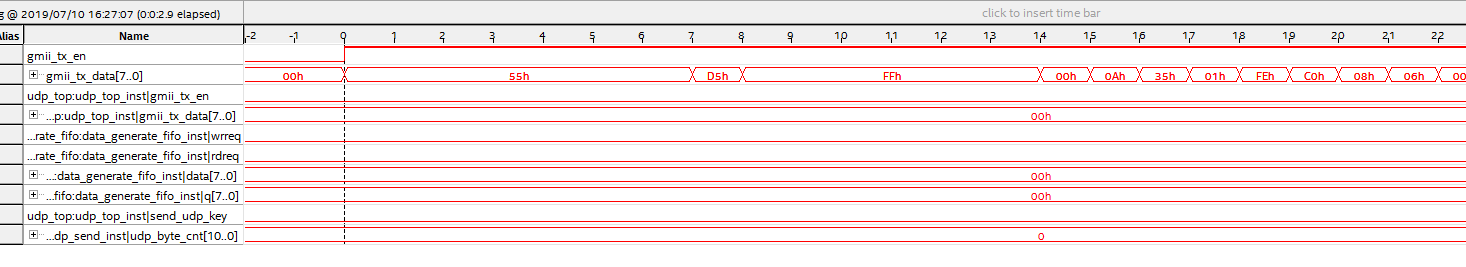
下面是用SignalTap抓取到的信号,如下图所示。
帧头部分:
帧尾FCS部分:
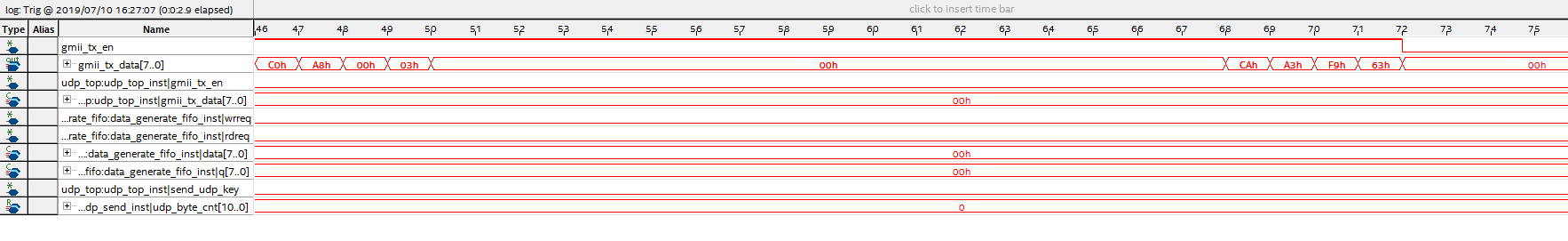
可以看出发送的校验码为0xca_a3_f9_63与CRC计算机软件计算结果一致。
3.1 ARP请求
FPGA实现ARP请求非常简单。首先定义模块信号。
module  arp_request(
        input                   clk                             ,//125M
        input                   rst_n                           ,
        input         [31: 0]   src_ip_addr                     ,
        input         [31: 0]   dest_ip_addr                    ,
        input         [47: 0]   src_mac_addr                    ,
        input         [47: 0]   dest_mac_addr                   ,
        input         [31: 0]   crc                             ,
        output  reg             crc_init                        ,
        output  reg             crc_en                          ,
        //gmii
        output  reg             gmii_tx_en                      ,
        output  reg   [ 7: 0]   gmii_tx_data
);
用计数器,在计数变化时,将每一个字节通过gmii_tx_data发送即可。具体请看工程源码。
3.2 ARP应答解析
在FPGA发送ARP请求后,对应IP地址将会做出APR应答发送其对应MAC地址,此时通过FPGA的ARP应答解析模块即可正确解析出目标MAC地址,从而为UDP协议传输奠定基础。
具体实现:
①判断目标MAC地址是否是FPGA设备的MAC地址
②判断操作码是否是0x0002
③判断PC端IP地址是否是192.168.0.3
④判断目的IP地址是否是192.168.0.2
只有以上条件均满足时,我们认为这是一条ARP应答包,从而更新IP为192.168.0.3对应的MAC地址。具体请看工程源码
4 UDP协议传输实现
在这里,我通过按键,生成1200个字节的数据,从0-255循环变化,然后封装成UDP包发送到PC端。从而实现UDP协议传输。
由上面UDP介绍,我们可以知道发送一个UDP包的主要构成,如下图所示:
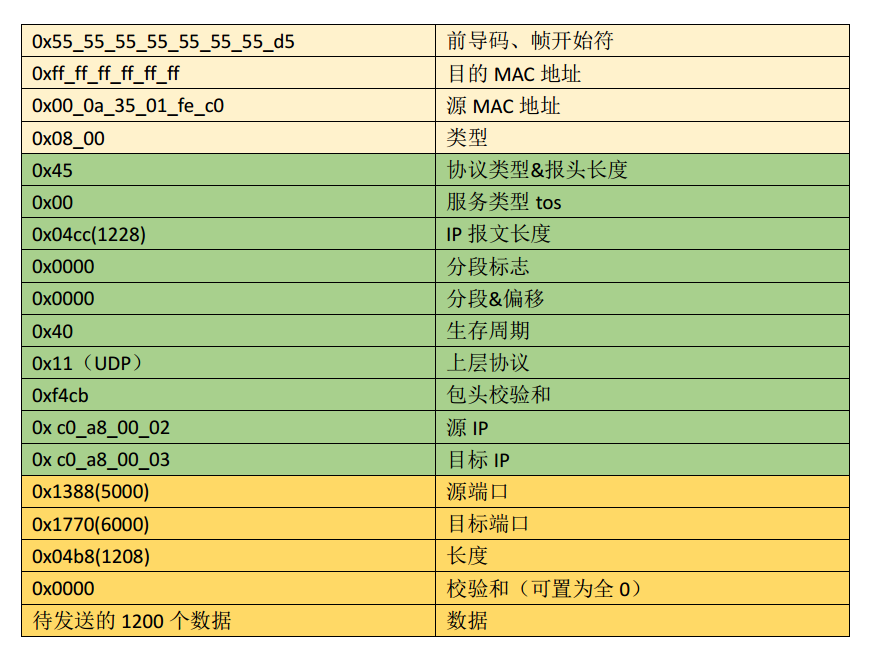
IP数据包的报头校验和:
0x4500+0x04cc+0x0000+0x0000+0x4011+0xc0a8+0x0002+0xc0a8+0x0003 = 0x20b32
0x0002+0x0b32 = 0x0b34
checksum = ~(0x0b34) = 0xf4cb
同样的,我们使用计数器来发送对应数据。
UDP发送模块如下:
module  udp_send(
        input                   clk                             ,
        input                   clk_50m                         ,
        input                   rst_n                           ,
        input         [31: 0]   src_ip_addr                     ,
        input         [31: 0]   dest_ip_addr                    ,
        input         [47: 0]   src_mac_addr                    ,
        input         [47: 0]   dest_mac_addr                   ,
        //fifo
        input         [10: 0]   fifo_rdusedw                    ,
        input         [ 7: 0]   fifo_rd_data                    ,
        output  reg             fifo_rdreq                      ,
        //crc
        input         [31: 0]   crc                             ,
        output  reg             crc_init                        ,
        output  reg             crc_en                          ,
        //gmii
        output  reg             gmii_tx_en                      ,
        output  reg   [ 7: 0]   gmii_tx_data
);
//======================================================================
//************** Define Parameter and Internal Signals *****************
//======================================================================/
parameter   DATA_LEN        =   16'd1200                        ;//发送的UDP数据长度

parameter   PREAMBLE        =   8'h55                           ;
parameter   SFD             =   8'hd5                           ;
parameter   LEN_TYPE        =   16'h0800                        ;

parameter   VER_HDR_LEN     =   8'h45                           ;
parameter   TOS             =   8'h00                           ;
parameter   TOTAL_LEN       =   DATA_LEN+28                     ;
parameter   ID              =   16'h0000                        ;
parameter   RSV_DF          =   8'h00                           ;
parameter   MF_FRAG_OFFSET  =   8'h00                           ;
parameter   TTL             =   8'h40                           ;
parameter   PROTOCOL        =   8'h11                           ;

parameter   SRC_PORT        =   16'd5000                        ;
parameter   DST_PORT        =   16'd6000                        ;
parameter   UDP_LEN         =   DATA_LEN+8                      ;
parameter   UDP_CHECKSUM    =   16'h0000                        ;


wire    [19: 0]                 ip_check_sum1                   ;
wire    [19: 0]                 ip_check_sum2                   ;
wire    [15: 0]                 ip_check_sum                    ;


reg                             trig_udp_send                   ;
reg                             flag_udp_send                   ;

reg     [10: 0]                 udp_byte_cnt                    ;
wire                            add_udp_byte_cnt                ;
wire                            end_udp_byte_cnt                ;

reg     [ 7: 0]                 udp_data                        ;
//======================================================================
//**************************** Main Code *******************************
//======================================================================/
//check_sum1 进位为17'hxff这种情况时,check_sum1,前16与后16位相加可能还会在第
//17位进1
assign  ip_check_sum1  =   {VER_HDR_LEN, 8'h00} + TOTAL_LEN + {TTL, PROTOCOL} + src_ip_addr[31:16] + src_ip_addr[15:0] + dest_ip_addr[31:16] + dest_ip_addr[15:0];//width<=20

//check_sum2
assign  ip_check_sum2   =   ip_check_sum1[19:16] + ip_check_sum1[15:0];//width<=17
assign  ip_check_sum    =   ~(ip_check_sum2[19:16] + ip_check_sum2[15:0]);//width<=16


//trig_udp_send
always  @(posedge clk or negedge rst_n)begin
    if(!rst_n)begin
        trig_udp_send   <=  1'b0;
    end
    else if(fifo_rdusedw == DATA_LEN-1)begin//
        trig_udp_send   <=  1'b1;
    end
    else begin
        trig_udp_send   <=  1'b0;
    end
end

//flag_udp_send
always  @(posedge clk or negedge rst_n)begin
    if(!rst_n)begin
        flag_udp_send   <=  1'b0;
    end
    else if(trig_udp_send)begin
        flag_udp_send   <=  1'b1;
    end
    else if(end_udp_byte_cnt)begin
        flag_udp_send   <=  1'b0;
    end
end

//udp_byte_cnt
always @(posedge clk or negedge rst_n)begin
    if(!rst_n)begin
        udp_byte_cnt <= 0;
    end
    else if(add_udp_byte_cnt)begin
        if(end_udp_byte_cnt)
            udp_byte_cnt <= 0;
        else
            udp_byte_cnt <= udp_byte_cnt + 1;
    end
end

assign  add_udp_byte_cnt    =       flag_udp_send;
assign  end_udp_byte_cnt    =       add_udp_byte_cnt && udp_byte_cnt == DATA_LEN+54-1;//前导码+分隔符8个,MAC帧头14,CRC校验4

//fifo_rdreq
always  @(posedge clk or negedge rst_n)begin
    if(!rst_n)begin
        fifo_rdreq   <=  1'b0;
    end
    else if(udp_byte_cnt == 50-1)begin
        fifo_rdreq   <=  1'b1;
    end
    else if(udp_byte_cnt == DATA_LEN+50-1)begin//校验码之前
        fifo_rdreq   <=  1'b0;
    end
end

//--------------------------------------------------------------------\
//gmii_tx_en
always  @(posedge clk or negedge rst_n)begin
    if(!rst_n)begin
        gmii_tx_en  <=  1'b0;
    end
    else if(flag_udp_send)begin
        gmii_tx_en  <=  1'b1;
    end
    else begin
        gmii_tx_en  <=  1'b0;
    end
end

//gmii_tx_data
always  @(posedge clk or negedge rst_n)begin
    if(!rst_n)begin
        gmii_tx_data    <=  8'h00;
    end
    else if(flag_udp_send)begin
        case(udp_byte_cnt)
            0,1,2,3,4,5,6:  gmii_tx_data    <=  PREAMBLE;
            7:              gmii_tx_data    <=  SFD;
            //帧头
            8:              gmii_tx_data    <=  dest_mac_addr[47:40];
            9:              gmii_tx_data    <=  dest_mac_addr[39:32];
            10:             gmii_tx_data    <=  dest_mac_addr[31:24];
            11:             gmii_tx_data    <=  dest_mac_addr[23:16];
            12:             gmii_tx_data    <=  dest_mac_addr[15: 8];
            13:             gmii_tx_data    <=  dest_mac_addr[ 7: 0];
            14:             gmii_tx_data    <=  src_mac_addr[47:40];
            15:             gmii_tx_data    <=  src_mac_addr[39:32];
            16:             gmii_tx_data    <=  src_mac_addr[31:24];
            17:             gmii_tx_data    <=  src_mac_addr[23:16];
            18:             gmii_tx_data    <=  src_mac_addr[15: 8];
            19:             gmii_tx_data    <=  src_mac_addr[ 7: 0];
            20:             gmii_tx_data    <=  LEN_TYPE[15: 8];
            21:             gmii_tx_data    <=  LEN_TYPE[ 7: 0];
            //IP
            22:             gmii_tx_data    <=  VER_HDR_LEN;//8'h45
            23:             gmii_tx_data    <=  TOS;
            24:             gmii_tx_data    <=  TOTAL_LEN[15: 8];
            25:             gmii_tx_data    <=  TOTAL_LEN[ 7: 0];
            26:             gmii_tx_data    <=  ID[15: 8];
            27:             gmii_tx_data    <=  ID[ 7: 0];
            28:             gmii_tx_data    <=  RSV_DF;
            29:             gmii_tx_data    <=  MF_FRAG_OFFSET;
            30:             gmii_tx_data    <=  TTL;
            31:             gmii_tx_data    <=  PROTOCOL;
            32:             gmii_tx_data    <=  ip_check_sum[15: 8];
            33:             gmii_tx_data    <=  ip_check_sum[ 7: 0];
            34:             gmii_tx_data    <=  src_ip_addr[31:24];
            35:             gmii_tx_data    <=  src_ip_addr[23:16];
            36:             gmii_tx_data    <=  src_ip_addr[15: 8];
            37:             gmii_tx_data    <=  src_ip_addr[ 7: 0];
            38:             gmii_tx_data    <=  dest_ip_addr[31:24];
            39:             gmii_tx_data    <=  dest_ip_addr[23:16];
            40:             gmii_tx_data    <=  dest_ip_addr[15: 8];
            41:             gmii_tx_data    <=  dest_ip_addr[ 7: 0];
            //udp
            42:             gmii_tx_data    <=  SRC_PORT[15: 8];
            43:             gmii_tx_data    <=  SRC_PORT[7 : 0];
            44:             gmii_tx_data    <=  DST_PORT[15: 8];
            45:             gmii_tx_data    <=  DST_PORT[7 : 0];
            46:             gmii_tx_data    <=  UDP_LEN[15: 8];
            47:             gmii_tx_data    <=  UDP_LEN[7 : 0];
            48:             gmii_tx_data    <=  UDP_CHECKSUM[15: 8];
            49:             gmii_tx_data    <=  UDP_CHECKSUM[7 : 0];
            //crc
            DATA_LEN+50:    gmii_tx_data    <=  ~{crc[24], crc[25], crc[26], crc[27], crc[28], crc[29], crc[30], crc[31]};
            DATA_LEN+51:    gmii_tx_data    <=  ~{crc[16], crc[17], crc[18], crc[19], crc[20], crc[21], crc[22], crc[23]};
            DATA_LEN+52:    gmii_tx_data    <=  ~{crc[8], crc[9], crc[10], crc[11], crc[12], crc[13], crc[14], crc[15]};
            DATA_LEN+53:    gmii_tx_data    <=  ~{crc[0], crc[1], crc[2], crc[3], crc[4], crc[5], crc[6], crc[7]};

            default:        gmii_tx_data    <=  fifo_rd_data;
        endcase
    end
    else begin
        gmii_tx_data    <=  8'h00;
    end
end

//---------------------------CRC-----------------------------------\
//crc_init
always  @(posedge clk or negedge rst_n)begin
    if(!rst_n)begin
        crc_init    <=  1'b0;
    end
    else if(udp_byte_cnt == (8-1))begin
        crc_init    <=  1'b1;
    end
    else begin
        crc_init    <=  1'b0;
    end
end

//crc_en
always  @(posedge clk or negedge rst_n)begin
    if(!rst_n)begin
        crc_en  <=  1'b0;
    end
    else if(udp_byte_cnt == (9-1))begin//9-1
        crc_en  <=  1'b1;
    end
    else if(udp_byte_cnt == (DATA_LEN+51-1))begin//1251-1
        crc_en  <=  1'b0;
    end
end
endmodule
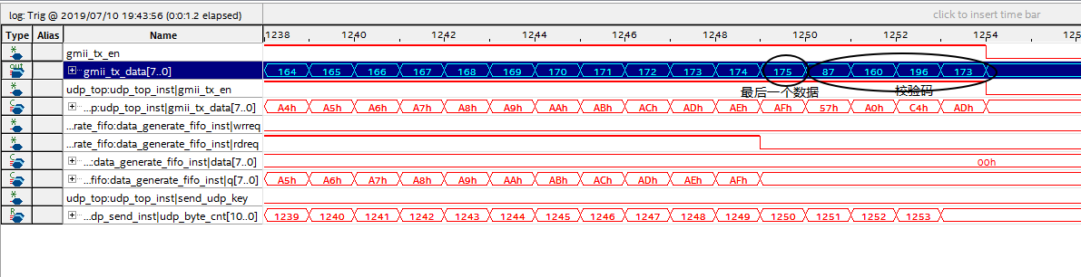
下面是用SignalTap抓取信号示意图
帧头部分,rdreq就是从fifp读取的数据然后通过封装成UDP发送
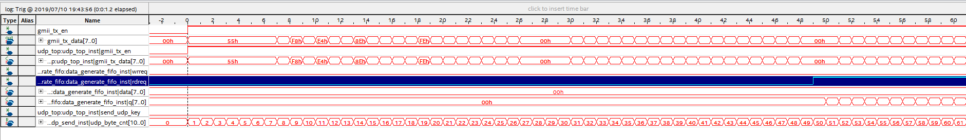
帧尾部分,可以看到,发送数据最后一个为175,的确发送了1200个数据(1199-1024=175)。
具体请看工程源码,然后自己下载跑一下就能理解了。
下面是工程源码下载链接基于FPGA的千兆以太网传输实例——ARP和UDP的实现
最后
以上就是大意月光最近收集整理的关于基于FPGA的千兆以太网传输实例——ARP和UDP的实现1 以太网原理介绍2 GMII接口介绍3 ARP协议实现4 UDP协议传输实现的全部内容,更多相关基于FPGA的千兆以太网传输实例——ARP和UDP的实现1内容请搜索靠谱客的其他文章。


发表评论 取消回复