目录
Fsm1
Fsm1s
Fsm2
Fsm3comb
Fsm1
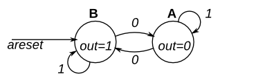
This is a Moore state machine with two states, one input, and one output. Implement this state machine. Notice that the reset state is B.
This exercise is the same as fsm1s, but using asynchronous reset.
Module Declaration
module top_module(
    input clk,
    input areset,    // Asynchronous reset to state B
    input in,
    output out);
这个题目给出了一个最简单的摩尔型的有限状态机,仅仅有两个状态,让你描述这个有限状态机:
采用三段式,给出设计如下:
module top_module(
    input clk,
    input areset,    // Asynchronous reset to state B
    input in,
    output out);//

    parameter A=0, B=1;
    reg state, next_state;

always @(posedge clk, posedge areset) begin    // This is a sequential always block
        // State flip-flops with asynchronous reset
        if(areset) state <= B;
        else state <= next_state;
    end

    always @(*) begin    // This is a combinational always block
        // State transition logic
        case(state)
            B: begin
                if(in == 1) next_state = B;
                else next_state = A;
            end
            A: begin
                if(in == 1) next_state = A;
                else next_state = B;
            end
        endcase
    end


    // Output logic
    // assign out = (state == ...);
    assign out = (state == A)?0:1;

endmodule
Fsm1s
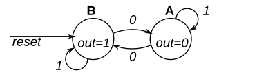
This is a Moore state machine with two states, one input, and one output. Implement this state machine. Notice that the reset state is B.
This exercise is the same as fsm1, but using synchronous reset.
Module Declaration
// Note the Verilog-1995 module declaration syntax here:
module top_module(clk, reset, in, out);
    input clk;
    input reset;    // Synchronous reset to state B
    input in;
    output out;
这个题目和上一句几乎一模一样,就是复位方式变成了同步复位;
可恨的是,题目还给了模板提示,提示用的是一段式,并且是Verilog1995,天了噜,这种风格,告辞了,三段式继续走起:
module top_module(
    input clk,
    input reset,    // Asynchronous reset to state B
    input in,
    output out);//

    parameter A=0, B=1;
    reg state, next_state;

always @(posedge clk) begin    // This is a sequential always block
        // State flip-flops with asynchronous reset
        if(reset) state <= B;
        else state <= next_state;
    end

    always @(*) begin    // This is a combinational always block
        // State transition logic
        case(state)
            B: begin
                if(in == 1) next_state = B;
                else next_state = A;
            end
            A: begin
                if(in == 1) next_state = A;
                else next_state = B;
            end
        endcase
    end


    // Output logic
    // assign out = (state == ...);
    assign out = (state == A)?0:1;

endmodule
Fsm2
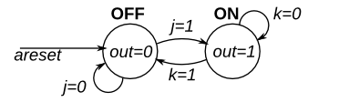
This is a Moore state machine with two states, two inputs, and one output. Implement this state machine.
This exercise is the same as fsm2s, but using asynchronous reset.
Module Declaration
module top_module(
    input clk,
    input areset,    // Asynchronous reset to OFF
    input j,
    input k,
    output out);
module top_module(
input clk,
input areset, // Asynchronous reset to OFF
input j,
input k,
output out); //
parameter OFF=0, ON=1;
reg state, next_state;
always @(*) begin
// State transition logic
case(state)
OFF: begin
if(j == 1) next_state = ON;
else next_state = OFF;
end
ON: begin
if(k == 1) next_state = OFF;
else next_state = ON;
end
endcase
end
always @(posedge clk, posedge areset) begin
// State flip-flops with asynchronous reset
if(areset) state <= OFF;
else state <= next_state;
end
// Output logic
// assign out = (state == ...);
assign out = (state == ON)? 1 : 0;
endmodule
Fsm3comb
The following is the state transition table for a Moore state machine with one input, one output, and four states. Use the following state encoding: A=2'b00, B=2'b01, C=2'b10, D=2'b11.
Implement only the state transition logic and output logic (the combinational logic portion) for this state machine. Given the current state (state), compute the next_state and output (out) based on the state transition table.
| State | Next state | Output | |
|---|---|---|---|
| in=0 | in=1 | ||
| A | A | B | 0 |
| B | C | B | 0 |
| C | A | D | 0 |
| D | C | B | 1 |
Module Declaration
module top_module(
    input in,
    input [1:0] state,
    output [1:0] next_state,
    output out);
本题和写全状态机没什么区别,只不过少了一个always时序逻辑块,当前状态由顶层模块给出,作为输入,下一个状态作为输出。
module top_module(
    input in,
    input [1:0] state,
    output [1:0] next_state,
    output out); //

    parameter A=0, B=1, C=2, D=3;

    // State transition logic: next_state = f(state, in)
    always@(*) begin
        case(state)
            A: begin
                if(in == 0) next_state = A;
                else next_state = B;
            end
            B: begin
                if(in == 0) next_state = C;
                else next_state = B;
            end
            C: begin
                if(in == 0) next_state = A;
                else next_state = D;
            end
            D: begin
                if(in == 0) next_state = C;
                else next_state = B;
            end
        endcase
    end

    // Output logic:  out = f(state) for a Moore state machine
    assign out = (state == D) ? 1:0;

endmodule
最后
以上就是欣慰方盒最近收集整理的关于HDLBits 系列(24)进入FSM(有限状态机)的世界入口的全部内容,更多相关HDLBits内容请搜索靠谱客的其他文章。


发表评论 取消回复