提示:文章写完后,目录可以自动生成,如何生成可参考右边的帮助文档
前言
此文承接上一篇《利用matlab工具生成5G NR信源》的补充和再理解
SSB参数的位置
在上一篇,我们讲到了5G NR信源的生成,上一篇提到了通过export matlab script生成代码来产生5G NR波形,但波形是产生了,但却怎么样都搜索不到PSS的位置。经过这几天的研究,终于慢慢搞清楚了原因。
原来,这个NR Test Models 看起来很SB,居然都不会默认生成一个SSB信号(super
SB o(∩_∩)o )。而PSS信号是包含在SSB块里面的。
看来有必要搞几篇文章来介绍理解<概念1:SSB>了,不过我们还是先看要怎么操作才能把SSB给生成出来吧
在matlab代码中,SSB的内容在这里
%% Synchronization Signals Burst
ssburst = nrWavegenSSBurstConfig;
ssburst.BlockPattern = 'Case B';
ssburst.TransmittedBlocks = [1 0 0 0];
ssburst.Period = 10;
ssburst.NCRBSSB = [];
ssburst.KSSB = 0;
ssburst.DataSource = 'MIB';
ssburst.DMRSTypeAPosition = 2;
ssburst.CellBarred = false;
ssburst.IntraFreqReselection = false;
ssburst.PDCCHConfigSIB1 = 0;
ssburst.SubcarrierSpacingCommon = 30;
ssburst.Enable = false;
ssburst.Power = 0;
cfgDLTM.SSBurst = ssburst;
看到了没: ssburst.Enable = false;
默认是不使能SSB信号的。
所以,第一步:ssburst.Enable = true;
那SSB的其他参数呢,也是很有必要要了解下的。这个nrWavegenSSBurstConfig就是表示SSB的一些其他配置,我们来看看。
SSB参数详细解释
1、Enable — Enable SS burst
Enable the SS burst in 5G waveform generation, specified as one of these values.
• 1 — Enable the SS burst.
• 0 — Disable the SS burst.
这个就是SSB信号的开关了
2、Power — Power scaling of SS burst in dB
0 (default) | real number
Power scaling of the SS burst in dB, specified as a real number. Use this property to scale the power of the SS burst in the generated 5G waveform.
这个就是SSB信号部分的功率设定
3、BlockPattern — Block pattern of SS burst
‘Case A’ (default) | ‘Case B’ | ‘Case C’ | ‘Case D’ | ‘Case E’
Block pattern of the SS burst, specified as one of these values corresponding to the patterns from TS 38.213 Section 4.1 [1].
• ‘Case A’ — Use this value for frequency range 1 (FR1) and 15 kHz SCS.
• ‘Case B’ or ‘Case C’ — Use either of these values for FR1 and 30 kHz SCS.
• ‘Case D’ — Use this value for frequency range 2 (FR2) and 120 kHz SCS.
• ‘Case E’ — Use this value for FR2 and 240 kHz SCS.
按我们目前来说一般都是FR1 and 30 kHz SCS这种配置。
4、TransmittedBlocks — Block transmission bitmap
[1 1 1 1] (default) | 4-bit, 8-bit, or 64-bit binary vector
Block transmission bitmap in a 5 ms half-frame burst, specified as a 4-bit or 8-bit binary vector for FR1 or a 64-bit binary vector for FR2. This vector specifies which SS blocks are active in the SS burst.
这个就是指示一个5ms内有几个SSB,对于Case B而言,SSB的位置分别为【4,8,16,20】个OFDM符号,这是我常用的
5、Period — Period of SS burst in ms
20 (default) | 5 | 10 | 40 | 80 | 160
Period of the SS burst in ms, specified as 5, 10, 20, 40, 80, or 160.
SSB的周期设定
6、NCRBSSB — Frequency offset from point A
[] (default) | integer from 0 to 2199
Frequency offset from point A, specified as [] or an integer from 0 to 2199. Point A is the center of subcarrier 0 in the common resource block 0 (CRB 0). This property specifies the frequency offset of the SS burst in resource blocks (RBs) relative to point A.
• For block pattern Case A, Case B and Case C, the unit of this property is expressed in terms of 15 kHz SCS.
• For block pattern Case D and Case E, the unit of this property is expressed in terms of 60 kHz SCS.
When NCRBSSB is an empty vector, [], the SS burst is positioned in the center of the carrier with the SCS corresponding to the block pattern specified by the BlockPattern property.
根据我的实验,
设置为0的时候为-45.54MHz
设置为1的时候为-45.54MHz + 180K
设置为2的时候为-45.54MHz + 360K
为啥这里说For block pattern Case A, Case B and Case C, the unit of this property is expressed in terms of 15 kHz SCS,它这的意思是15kHz为1个单位吗?但实际上不是啊,不知道哪里没理解对
7、KSSB — Subcarrier offset
0 (default) | integer from 0 to 23
Subcarrier offset, specified as one these options.
• For FR1:
o If SubcarrierSpacingCommon is 15, specify this property as an integer from 0 to 11.
o If SubcarrierSpacingCommon is 30, specify this property as an integer from 0 to 23.
In both cases, units are in terms of 15 kHz SCS. For block pattern Case B, KSSB must be even.
• For FR2, specify this property as an integer from 0 to 11. For block pattern Case D, KSSB must be even. For block pattern Case E, KSSB must be a multiple of 4. Units are in terms of SCS equal to the SubcarrierSpacingCommon property value.
The object increases the frequency offset of the SS burst from point A by KSSB subcarriers.
这个没用到,默认设置为0即可
8、DataSource — Source of SS burst payload
‘MIB’ (default) | ‘PN9-ITU’ | ‘PN9’ | ‘PN11’‘PN15’ | ‘PN23’ | two-element cell array | 24-bit binary vector
Source of the SS burst payload, specified as one of these options.
• ‘MIB’, ‘PN9-ITU’, ‘PN9’, ‘PN11’, ‘PN15’, or ‘PN23’
• Two-element cell array consisting of one of the character vectors from the previous list and a random numeric seed (for example, {‘PN9’,7})
• 24-bit binary vector
If you do not specify a random seed, all shift registers are initialized with an active state.
9、DMRSTypeAPosition — Position of first DM-RS symbol
2 (default) | 3
Position of the first demodulation reference signal (DM-RS) symbol in the physical downlink shared channel (PDSCH) system information block type 1 (SIB1), specified as 2 or 3.
10、CellBarred — Cell barring
0 (default) | 1
Cell barring, specified as 0 or 1. When CellBarred is set to 1, the cell enables the user equipment (UE) to camp on the cell.
11、CellBarred — Cell barring
0 (default) | 1
Cell barring, specified as 0 or 1. When CellBarred is set to 1, the cell enables the user equipment (UE) to camp on the cell.
12、IntraFreqReselection — Enable intrafrequency reselection
0 (default) | 1
Enable intrafrequency reselection, specified as one of these values.
• 0 — Disable intrafrequency reselection.
• 1 — Enable intrafrequency reselection of the same frequency cells.
13、PDCCHConfigSIB1 — Configuration type of PDCCH SIB1
0 (default) | integer from 0 to 255
Configuration type of the physical downlink control channel (PDCCH) SIB1, specified as an integer from 0 to 255.
14、SubcarrierSpacingCommon — SIB1 SCS in kHz
15 (default) | 30 | 60 | 120
SIB1 SCS in kHz, specified as one of these values.
• 15 or 30 for FR1
• 60 or 120 for FR2
这个,我们一般都是选30
第7-13点由于我还处于知识荒漠阶段,暂时不太清楚这些设置有什么具体作用,不过,对于我目前只关注5G SSB位置定位而言,暂时也不需要,希望再以后的学习中慢慢补充。
因此,我将这部分配置重新更新为:
%% Synchronization Signals Burst
ssburst = nrWavegenSSBurstConfig;
ssburst.BlockPattern = 'Case B';
ssburst.TransmittedBlocks = [1 0 0 0];
ssburst.Period = 20; %SSB的周期5ms, 10ms, 20ms
ssburst.NCRBSSB = [];
ssburst.KSSB = 0;
ssburst.DataSource = 'MIB';
ssburst.DMRSTypeAPosition = 2;
ssburst.CellBarred = false;
ssburst.IntraFreqReselection = false;
ssburst.PDCCHConfigSIB1 = 0;
ssburst.SubcarrierSpacingCommon = 30;
ssburst.Enable = true; %使能SSB
ssburst.Power = 10;
%SSB的功率
cfgDLTM.SSBurst = ssburst;
这样就能出来SSB信号了。
信号时频图
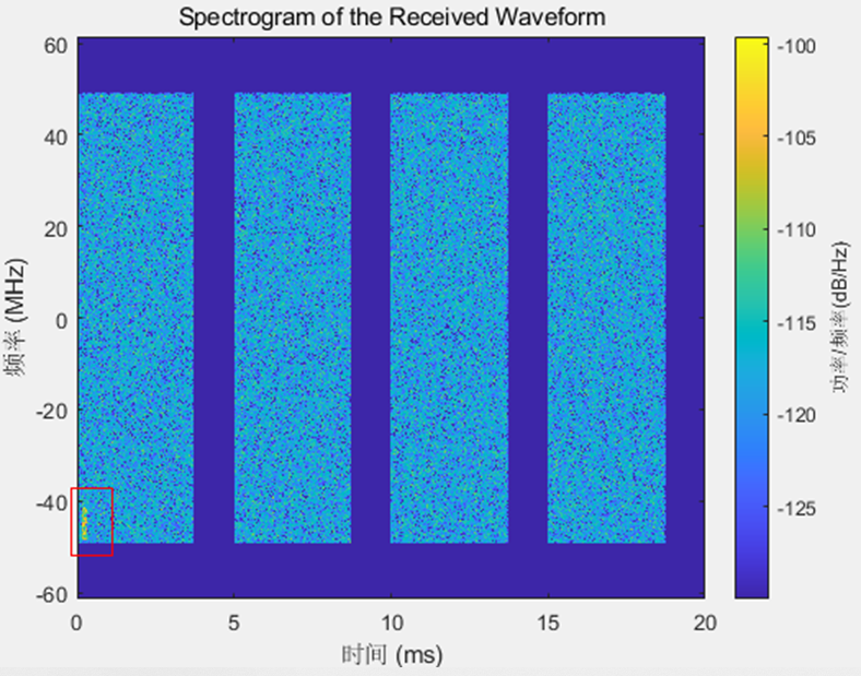
这里有一个看时频功率的函数很好用spectrogram
spectrogram(lte_data1(:,1),ones(4096,1),0,4096,‘centered’,122.88e6,‘yaxis’,‘MinThreshold’,-130);
ones(4096,1):矩形窗
4096:每次FFT点数
122.88e6:采样率
也就是33.333us的数据做一次FFT。
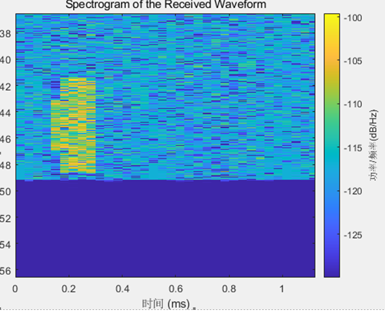
这里我们把SSB的功率设置大一点,设置为10,可以让SSB看起来更明显

放大一点看就特别明显了

总结
5G NR和4G LTE在PSS和SSS的处理还是有不少差异的,4G LTE的PSS和SSS频率的位置就是在中心频点,时域的位置也是固定在某个时隙不能配置。
而5G NR却是以SSB块的形式存在,而且SSB的频域位置是可以配置的,时域的位置有好几个可能的点,而且SSB的周期也是可以配的,好像一般是20ms一个周期。而且同一个5ms可以配出好几个SSB。
虽然这些东西我可以不用管,都是物理层算法的事情,奈何俺就是一个喜欢细扣的人,不折腾折腾不搞明白就不罢休。因此后续这个系列的的文章我需要将5G NR的一些时频结构、特别是关于SSB的结构。以及PSS、SSS码在频域的信号以及转换到时域的信号,以及PSS、SSS的同步过程一步一步搞清楚。
需要搞清楚的名词和机制
1、 CASE A ~ E
2、 FR1 /FR2
3、 point A
4、 SSB以及包含的内容
5、 SSB是如何分配的
最后还有一个OFDM的调制,尽管PSS和SSS这里已经设计到了OFDM调制解调,不过PSS和SSS的生成还是比较简单的,时间充裕一点的时候我要花点的理解学习OFDM调制解调,希望能够理解整个基带信号是如何生成的,最好要具备一些FPGA实现的能力
我觉得我至少要搞清楚这些东西,也不枉我5G信号处理走一遭。
一篇文章写起来至少两三个小时,大部分看官却只收藏而不点赞,久而久之就坚持不下去了,有时候都不知道是为了什么。各位多点点赞了
最后
以上就是复杂小蜜蜂最近收集整理的关于5G NR学习理解系列——MATLAB5G信源的生成之SSB参数配置前言SSB参数的位置SSB参数详细解释信号时频图总结的全部内容,更多相关5G内容请搜索靠谱客的其他文章。


发表评论 取消回复