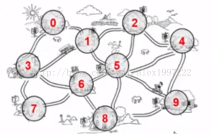
图是表示“多对多的关a系”
包含:
一组顶点, 通常用V表示顶点集合
一组边:通常用E表示边的集合
边是顶点对:(v,w)表示从V指向W(无向边)
有向边<v,w> 表示从v指向w的边---> 单行线
不考虑重边和回路
图的类型:
无向图:没有方向的图
有向图:拥有方向的图,两条点之间的边带有箭头
网络图:边带权重的图
如何在程序中实现一个图?
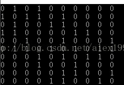
(1)邻接矩阵->G[N][N]

实现程序如下:
#include<iostream>
#include<algorithm>
#define N 10
using namespace std;
int G[N][N];

int main() {

	for (int i = 0; i < N; ++i)
		for (int j = 0; j < N; ++j) {

			G[i][j] = 0;
			if (i == 0 && (j == 1 || j == 3))
				G[i][j] = 1;
			if (i == 1 && (j == 0 || j == 3 || j == 2 || j == 5))
				G[i][j] = 1;
			if (i == 2 && (j == 1 || j == 4 || j == 5))
				G[i][j] = 1;
			if (i == 3 && (j == 0 || j == 1 || j == 6 || j == 7))
				G[i][j] = 1;
			if (i == 4 && (j == 2 || j == 5 || j == 9))
				G[i][j] = 1;
			if (i == 5 && (j == 1 || j == 2 || j == 4 || j == 6 || j == 8 || j == 9))
				G[i][j] = 1;
			if (i == 6 && (j == 3 || j == 5 || j == 7 || j == 8))
				G[i][j] = 1;
			if (i == 7 && (j == 3 || j == 6))
				G[i][j] = 1;
			if (i == 8 && (j == 5 || j == 6 || j == 9))
				G[i][j] = 1;
			if (i == 9 && (j == 4 || j == 5 || j == 8))
				G[i][j] = 1;
		}

	for (int i = 0; i < N; ++i) {
		for (int j = 0; j < N; ++j) {
			cout << G[i][j] << "  ";
		}
		cout << endl;
	}

	system("PAUSE");
	return 0;
}
观察可得: 斜对角矩阵全为0 意思是一个点到自己的距离
以斜对角为轴 该图是对称的
所以空间上有浪费
度的概念: 入度指向这条边的边的条数
出度:从一个度出发 指向别的边
邻接表的表示方法:
邻接表:G[N]为指针数组,对应矩阵每行一个列表
只存非0元素
图的建立:
邻接矩阵表示法
#include<iostream>
#include<algorithm>
#include<stdlib.h>
#define MAXSIZE 10
using namespace std;
typedef int weightType;

class eEdge {
	friend class GraphicOperation;
private:
	int V1;  //顶点1
	int V2;  //顶点2
	weightType weight;  //一条边的权重

};


class Graphic {   //图框架的定义
	friend class GraphicOperation;
private:
	int Nv;  //顶点的个数
	int Ne;  //边的个数
	weightType G[MAXSIZE][MAXSIZE];   //用来存放顶点关系的二维数组
};


class GraphicOperation {
private:
	Graphic* ObjectGrahpic;
public:
	GraphicOperation() {
		ObjectGrahpic = new Graphic();   //创建对象
	}
	void CreateGraphic(int vertexNum);  //创建一个图  初始化:只有顶点没有边
	void InsertGraphic(eEdge* E);       //插入一条边

	void BuildGraphic();                //图的建立
};


void GraphicOperation::CreateGraphic(int vertexNum) {
	ObjectGrahpic->Nv = vertexNum;
	ObjectGrahpic->Ne = 0;

	for (int V = 0; V < ObjectGrahpic->Nv; ++V)
		for (int E = 0; E < ObjectGrahpic->Nv; ++E)
			ObjectGrahpic->G[V][E] = 0;      //图的初始化工作

}


void GraphicOperation::InsertGraphic(eEdge* E) {   //在图中插入一条边

	ObjectGrahpic->G[E->V1][E->V2] = E->weight;   //无向图只需插入一条边

	ObjectGrahpic->G[E->V2][E->V1] = E->weight;   //有向图需插入两次
}


void GraphicOperation::BuildGraphic() {

    //首先读入顶点
	int vertexNum;
	cin >> vertexNum;
	CreateGraphic(vertexNum);

	//然后读入边
	int edgeNums;
	cin >> edgeNums;
	ObjectGrahpic->Ne = edgeNums; //边的条数

	//之后创建边并插入
	if (ObjectGrahpic->Ne != 0) {
		eEdge* E = new eEdge();
		for (int i = 0; i < ObjectGrahpic->Ne; ++i) {
			cin >> E->V1 >> E->V2 >> E->weight;
			InsertGraphic(E);   //把边插入即可
		}
	}
}
邻接表的使用:
首先定义顶点
class Vnode {
	friend class VnodeAdjList;
private:
	adjVnode* FirstEdge;  //指向下一条边
	dataType data;        //存放的数据
};
然后定义协调顶点和边的模块
class adjVnode {
	friend class adjVNode;  //调节节点
public:
	verTex Adj;         //下一个顶点的信息
	weightType Weight;  //边的权重

	adjVnode* next;     //指向下一个节点

};
存储边的信息
class eEdge {
	friend class GraphicOperation;
private:
	int V1;             //顶点1
	int V2;             //顶点2
	weightType weight;  //一条边的权重

};
图的框架
//存放图的数据
class Graphic {
	friend class GraphicOperation;
public:
	int Nv;  //顶点的个数
	int Ne;  //边的条数
	Vnode G[MAXSIZE];  //用来存放顶点

};
图的创建操作(和邻接矩阵相似)
void GraphicOperation::CreateGraphic(int VertexNum) {
	verTex V, W;

	objGrahpic->Nv = VertexNum;   //先初始化顶点
	objGrahpic->Ne = 0;           //后将边初始化为0

	for (int V = 0; V < objGrahpic->Nv; ++V) {
		objGrahpic->G[V].FirstEdge = NULL;      //把每一个顶点的初始边设置为0
	}
}
边的插入操作
//边的插入
void GraphicOperation::InsertEdge(eEdge* edge) {

	adjVnode* newNode = new adjVnode();  //创建一个新的节点
	newNode->Weight = edge->weight;
	newNode->Adj = edge->V2;  //指向的下一个顶点

	//节点的插入
	newNode->next = objGrahpic->G[edge->V1].FirstEdge;
	objGrahpic->G[edge->V1].FirstEdge = newNode;

}
插入操作示意图:

最后
以上就是顺心奇异果最近收集整理的关于数据结构 图的初始化的全部内容,更多相关数据结构内容请搜索靠谱客的其他文章。
本图文内容来源于网友提供,作为学习参考使用,或来自网络收集整理,版权属于原作者所有。


发表评论 取消回复