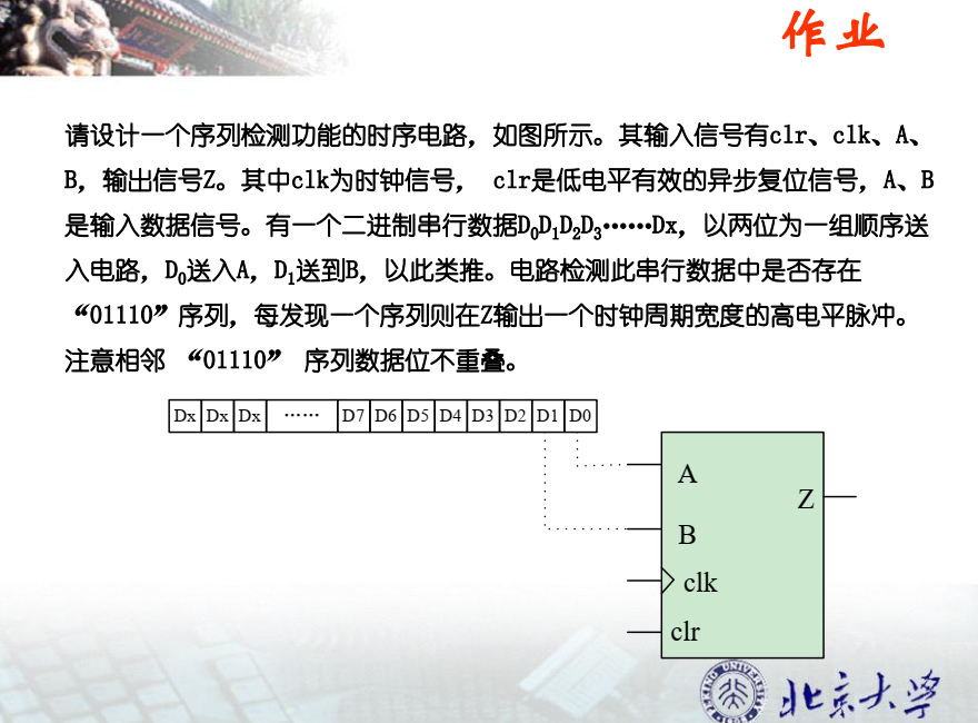
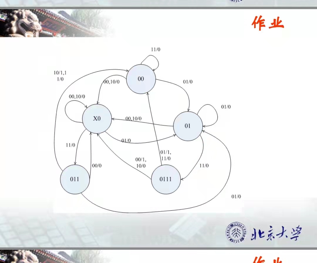
上代码:
module timecheck(CLR,CLK,A,B,Z);
input CLR,CLK,A,B;
output Z;
reg Z;
wire [1:0]DATA_IN;
reg [3:0]STATE;

parameter   state_idle     =  4'b00x0,
             state_match1   =  4'b0000,
             state_match2   =  4'b0001,
             state_match3   =  4'b0011,
             state_match4   =  4'b0111;
assign       DATA_IN = {A,B};

initial begin
    STATE =state_idle;
end

always @(posedge CLK or posedge CLR)
begin
        if(~CLR)
        begin
            Z<=0;
            STATE <=state_idle;
        end
        else
        case(STATE)

        state_idle:
        if((DATA_IN==2'b00) || (DATA_IN==2'b10 ))
        begin
            STATE <=state_idle;
            Z<=0;
        end
        else if(DATA_IN==2'b01)
        begin
            STATE <=state_match2;
            Z<=0;
        end
        else if(DATA_IN==2'b11)
        begin
            STATE <=state_match3;
            Z<=0;
        end

        state_match1:
        if((DATA_IN==2'b00) || (DATA_IN==2'b10 ))
        begin
            STATE <=state_idle;
            Z<=0;
        end
        else if(DATA_IN==2'b01)
        begin
            STATE <=state_match2;
            Z<=0;
        end
        else if(DATA_IN==2'b11)
        begin
            STATE <=state_match1;
            Z<=0;
        end

        state_match2:
        if((DATA_IN==2'b00) || (DATA_IN==2'b10 ))
        begin
            STATE <=state_idle;
            Z<=0;
        end
        else if(DATA_IN==2'b01)
        begin
            STATE <=state_match2;
            Z<=0;
        end
        else if(DATA_IN==2'b11)
        begin
            STATE <=state_match4;
            Z<=0;
        end

        state_match3:
        if(DATA_IN==2'b00)
        begin
            STATE <=state_idle;
            Z<=0;
        end
        else if(DATA_IN==2'b01)
        begin
            STATE <=state_match2;
            Z<=0;
        end
        else if(DATA_IN==2'b11)
        begin
            STATE <=state_match1;
            Z<=0;
        end
        else if(DATA_IN==2'b10)
        begin
            STATE <=state_match1;
            Z<=1;
        end

        state_match4:
        if(DATA_IN==2'b00)
        begin
            STATE <=state_idle;
            Z<=1;
        end
        else if(DATA_IN==2'b10)
        begin
            STATE <=state_idle;
            Z<=0;
        end
        else if(DATA_IN==2'b01)
        begin
            STATE <=state_match1;
            Z<=1;
        end
        else if(DATA_IN==2'b11)
        begin
            STATE <=state_match1;
            Z<=0;
        end
endcase
end
endmodule
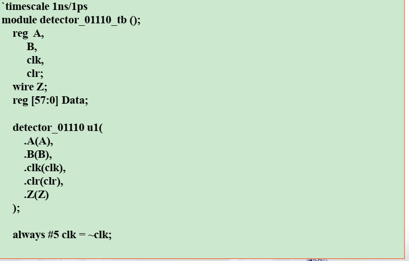
测试代码:
`timescale 1ns / 1ns
module tb_timecheck();
reg clr,clk,a,b;
wire z;

parameter data_input = 20'b1010_1110_0111_0111_0001;
reg [4:0] i;
timecheck tb_time(.CLR(clr),.CLK(clk),.A(a),.B(b),.Z(z));

initial begin
    clr= 0;
    a=0;
    b=0;
    clk=0;
    i=5'd0;
    #5
    clr =1;
end
always  #5 clk = ~ clk;

always @(posedge clk or posedge clr)
begin
    if(~clr)
       begin
            i<=5'd0;
       end
    else if (i<5'd20)
       begin
            a<=data_input[i];
            b<=data_input[i+1];
            i<=i+5'd2;
       end
       else
       begin
            i<=5'd2;
            a<=data_input[0];
            b<=data_input[1];
       end
end
endmodule
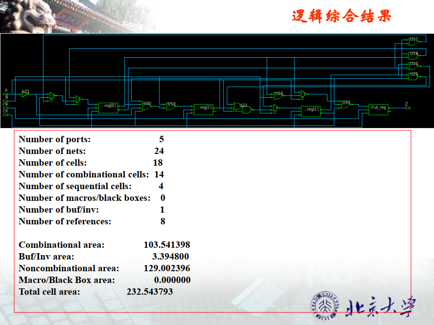
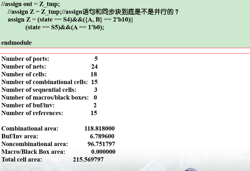
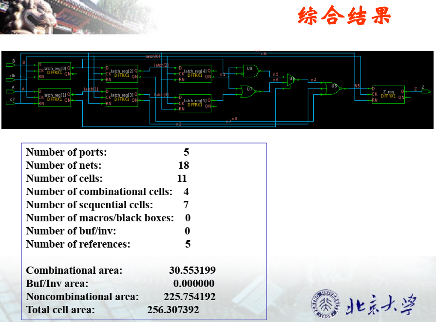
综合电路图: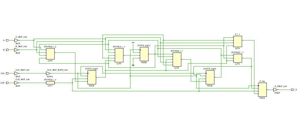
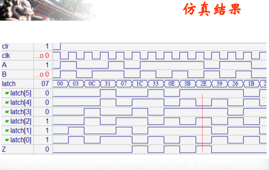
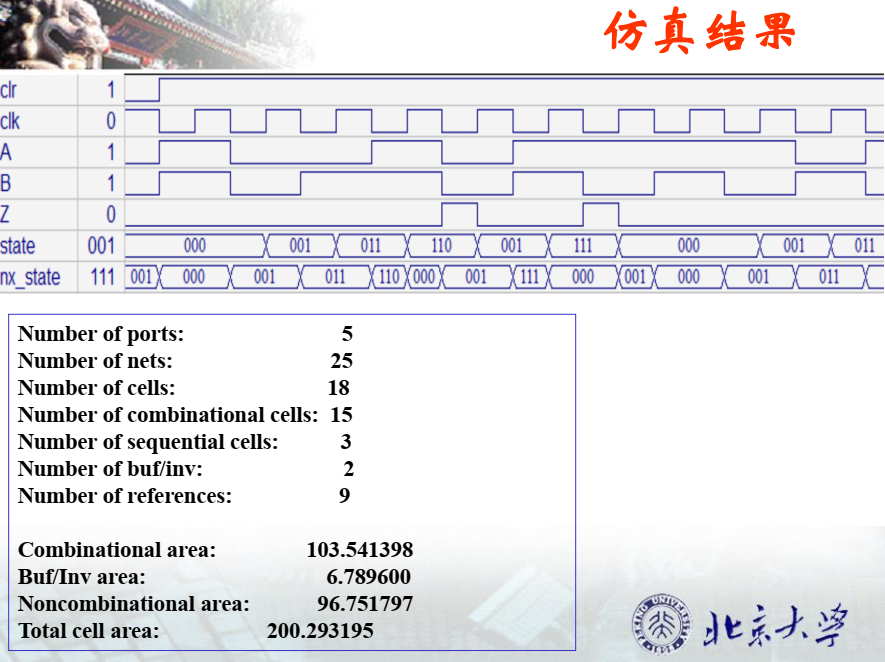
仿真波形:
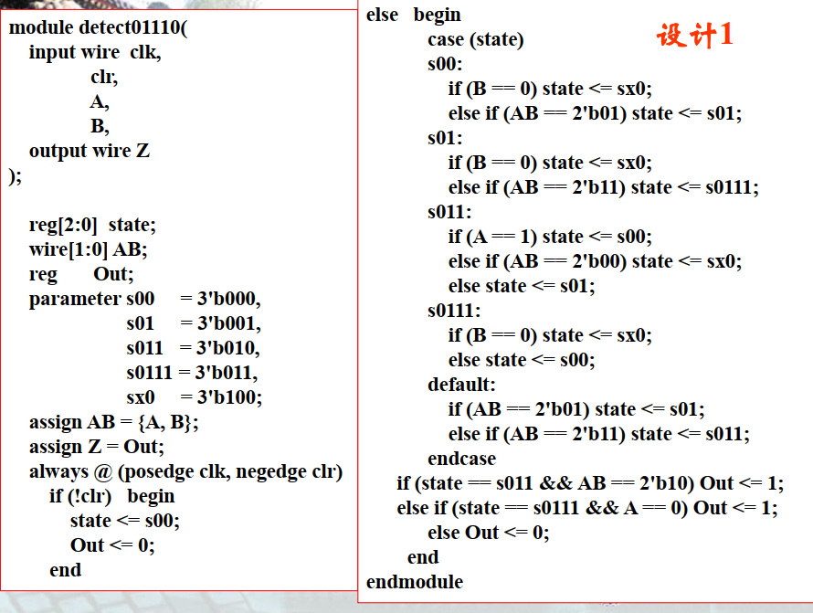
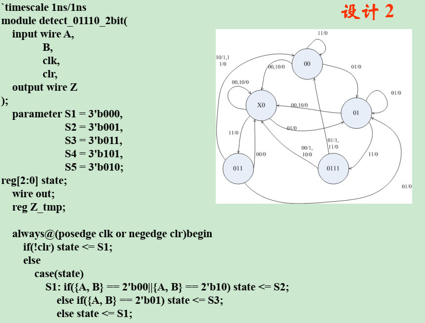
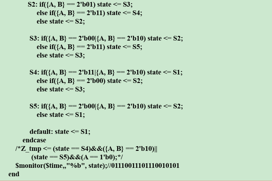
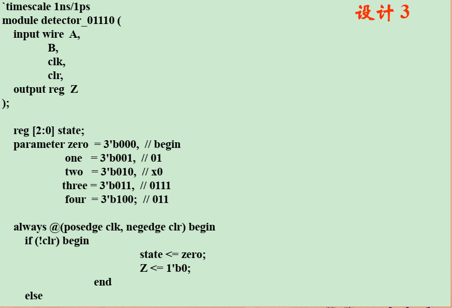
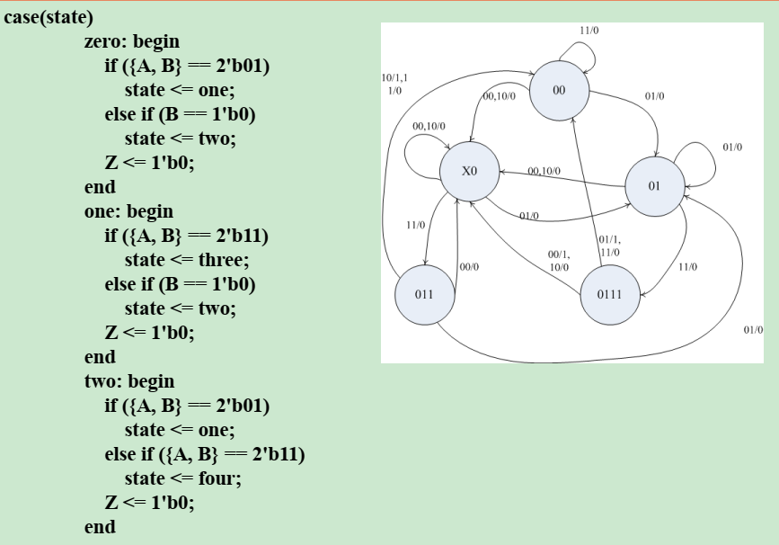
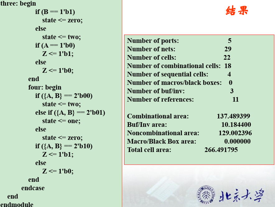
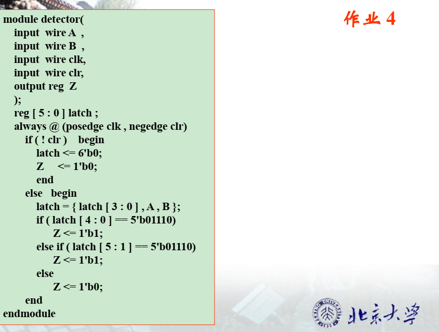
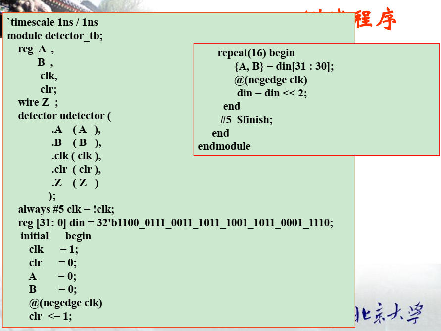
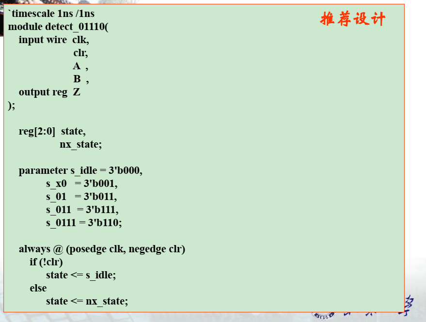
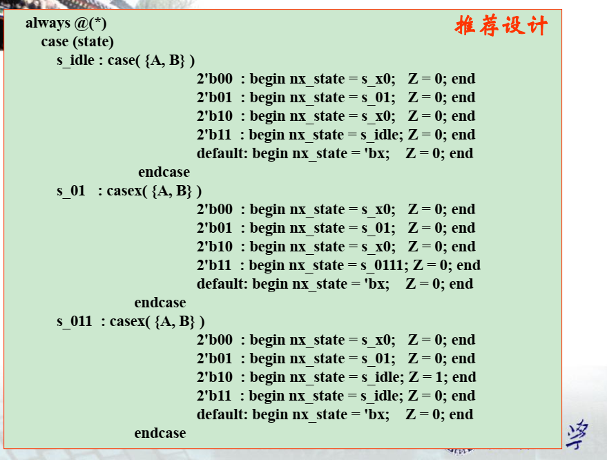
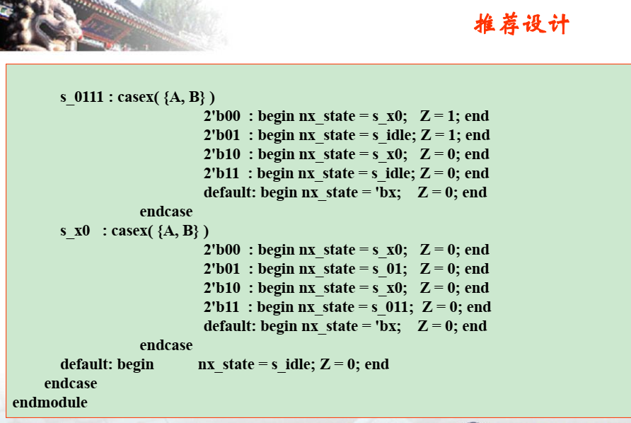
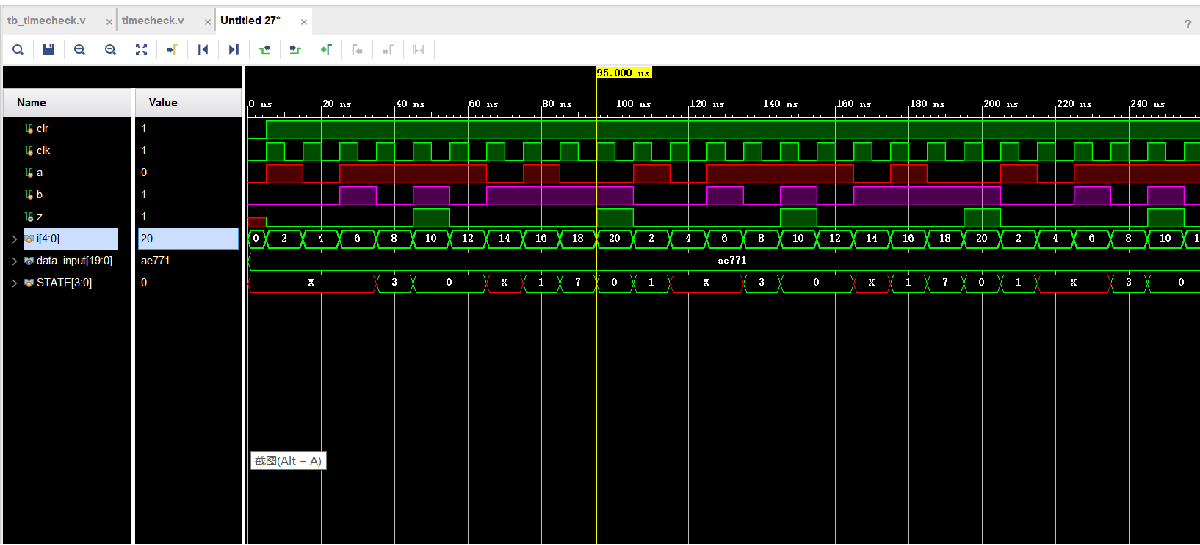 同学做的比我好多了,上图:

![]()
最后
以上就是耍酷往事最近收集整理的关于序列检测功能的时序电路(verilog 01110)的全部内容,更多相关序列检测功能的时序电路(verilog内容请搜索靠谱客的其他文章。
本图文内容来源于网友提供,作为学习参考使用,或来自网络收集整理,版权属于原作者所有。


发表评论 取消回复