上一篇博文中注释了SPI外设模块,现在来介绍timer定时器模块。
另外,在最后一个章节中会上传额外添加详细注释的工程代码,完全开源,如有需要可自行下载。
目录
0 RISC-V SoC注解系列文章目录
1. 结构
2. timer模块
2.1 输入和输出端口
2.2 程序注解
3. 总结
参考:
0 RISC-V SoC注解系列文章目录
零、RISC-V SoC软核笔记详解——前言
一、RISC-V SoC内核注解——取指
二、RISC-V SoC内核注解——译码
三、RISC-V SoC内核注解——执行
四、RISC-V SoC内核注解——除法(试商法)
五、RISC-V SoC内核注解——中断
六、RISC-V SoC内核注解——通用寄存器
七、RISC-V SoC内核注解——总线
八、RISC-V SoC外设注解——GPIO
九、RISC-V SoC外设注解——SPI接口
十、RISC-V SoC外设注解——timer定时器
十一、RISC-V SoC外设注解——UART模块(终篇)
1. 结构
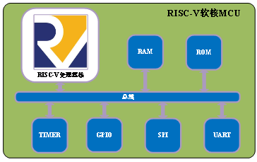
如下图,TIMER模块也是通过总线与内核进行交互的。该模块的主要功能是通过计数器达到计数阈值,来触发定时器中断。

2. timer模块
2.1 输入和输出端口
    input wire clk,
    input wire rst,
 //内核给外设
    input wire[31:0] data_i,
    input wire[31:0] addr_i,
    input wire we_i,
 //外设给内核
    output reg[31:0] data_o,
    output wire int_sig_o  //中断信号
2.2 程序注解
Step1:定义三个寄存器
1、控制寄存器:REG_CTRL
// [0]: timer enable 使能后计数器开始计数
// [1]: timer int enable 定时器中断使能(这个信号使能后,才表示我要发出中断信号)
// [2]: timer int pending, write 1 to clear it ,定时器中断等待信号,置1清0(清除C语言中的1),如下:timer_ctrl <= {data_i[31:3], (timer_ctrl[2] & (~data_i[2])), data_i[1:0]};
//虽然不清楚为什么C语言中不直接给0,但是给1之后,用硬件清零也是可以的。
//*中断的等待(pending)状态,有效时表示定时器中断正在等待(pending)*//
// addr offset: 0x00
2、计数阈值寄存器:REG_VALUE
3、当前计数值寄存器(只读):REG_COUNT
// [0]: timer enable 1
// [1]: timer int enable 1
// [2]: timer int pending, write 1 to clear it ,C代码中初始化置1清零 1
中断的等待(pending)状态,有效时表示表示定时器中断正在等待(pending)*//
// addr offset: 0x00
reg[31:0] timer_ctrl;

// timer current count, read only
// addr offset: 0x04
reg[31:0] timer_count;

// timer expired value
// addr offset: 0x08
reg[31:0] timer_value; //设置阈值Step2:给这三个寄存器规划地址
//寄存器地址规划
   localparam REG_CTRL = 4'h0; //定时器使能 定时器中断使能
   localparam REG_COUNT = 4'h4; //定时器计数器(只读类型)
localparam REG_VALUE = 4'h8; //设置阈值Step3:对寄存器进行读写
(这部分与其他外设的读写大致相同,下面重点说明一下不同的地方,即主要对REG_CTRL这个寄存器的读写进行说明)。
1.C代码中(定时器初始化):
TIMER0_REG(TIMER0_CTRL) = 0x07;//作者代码中就是这么写的 2.对应于硬件:
REG_CTRL = 32'b0111; 初始化状态时:使能定时器,使能定时器中断,清0中断等待位(置1清0);
if (we_i == `WriteEnable) begin
    case (addr_i[3:0])
        REG_CTRL: begin
            //timer_ctrl[2] 写1清0
            timer_ctrl <= {data_i[31:3], (timer_ctrl[2] & (~data_i[2])), data_i[1:0]};
        end                             //                    ~1 = 0
        REG_VALUE: begin
            timer_value <= data_i;
        end
    endcase
当定时器计数到计数阈值时,失能定时器,并将定时器等待位置1,以此判断触发定时器中断:
if ((timer_ctrl[0] == 1'b1) && (timer_count >= timer_value))
   //定时器达到计数阈值,中断的等待(pending)状态置为1,触发中断(硬件中将 timer_ctrl[2]拉高之后)
   begin
        timer_ctrl[0] <= 1'b0;
        timer_ctrl[2] <= 1'b1;
   end
assign int_sig_o是最终的中断信号,定时器中断使能 且 定时器达到计数阈值 发出中断信号,通过取指打拍模块if_id传给中断模块clint模块进行中断仲裁及处理
assign int_sig_o = ((timer_ctrl[1] == 1'b1) && (timer_ctrl[2] == 1'b1))? `INT_ASSERT: `INT_DEASSERT; 3. 总结
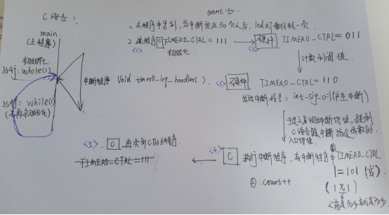
为了使得整个流程更加清晰,我们把作者的C代码和梳理的流程图放在下面。
作者写的相应的C代码如下:
#include <stdint.h>
#include "../include/timer.h"
#include "../include/gpio.h"
#include "../include/utils.h"

static volatile uint32_t count;
//主程序
int main()
{
    count = 0;

#ifdef SIMULATION
    TIMER0_REG(TIMER0_VALUE) = 500;     // 10us period
    TIMER0_REG(TIMER0_CTRL) = 0x07;     // enable interrupt and start timer

    while (1) {
        if (count == 2) {
            TIMER0_REG(TIMER0_CTRL) = 0x00;   // stop timer
            count = 0;
            // TODO: do something
            set_test_pass();
            break;
        }
    }
#else
    TIMER0_REG(TIMER0_VALUE) = 500000;  // 10ms period
    TIMER0_REG(TIMER0_CTRL) = 0x07;     // enable interrupt and start timer

    GPIO_REG(GPIO_CTRL) |= 0x1;  // set gpio0 output mode

    while (1) {
        // 500ms
        if (count == 50) {
            count = 0;
            GPIO_REG(GPIO_DATA) ^= 0x1; // toggle led
        }
    }
#endif

    return 0;
}

//中断程序(C代码中触发中断事件并清除标志位REG_CTRL[2])
void timer0_irq_handler()
{
    TIMER0_REG(TIMER0_CTRL) |= (1 << 2) | (1 << 0);  // clear int pending and start timer
//(1 << 2)=100   (1 << 0)=1
//(1 << 2) | (1 << 0)=101
//TIMER0_CTRL=TIMER0_CTRL|101
//因此当触发中断之后,清除定时器中断等待位REG_CTRL[2](在C语言中将REG_CTRL[2]置1)
//并 使能定时器REG_CTRL[0](计数器开始重新计数)。

    count++;
}
流程总结:

最后
以上就是干净夏天最近收集整理的关于十、RISC-V SoC外设——timer定时器 代码讲解的全部内容,更多相关十、RISC-V内容请搜索靠谱客的其他文章。


发表评论 取消回复