文章目录
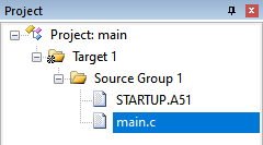
工程结构:
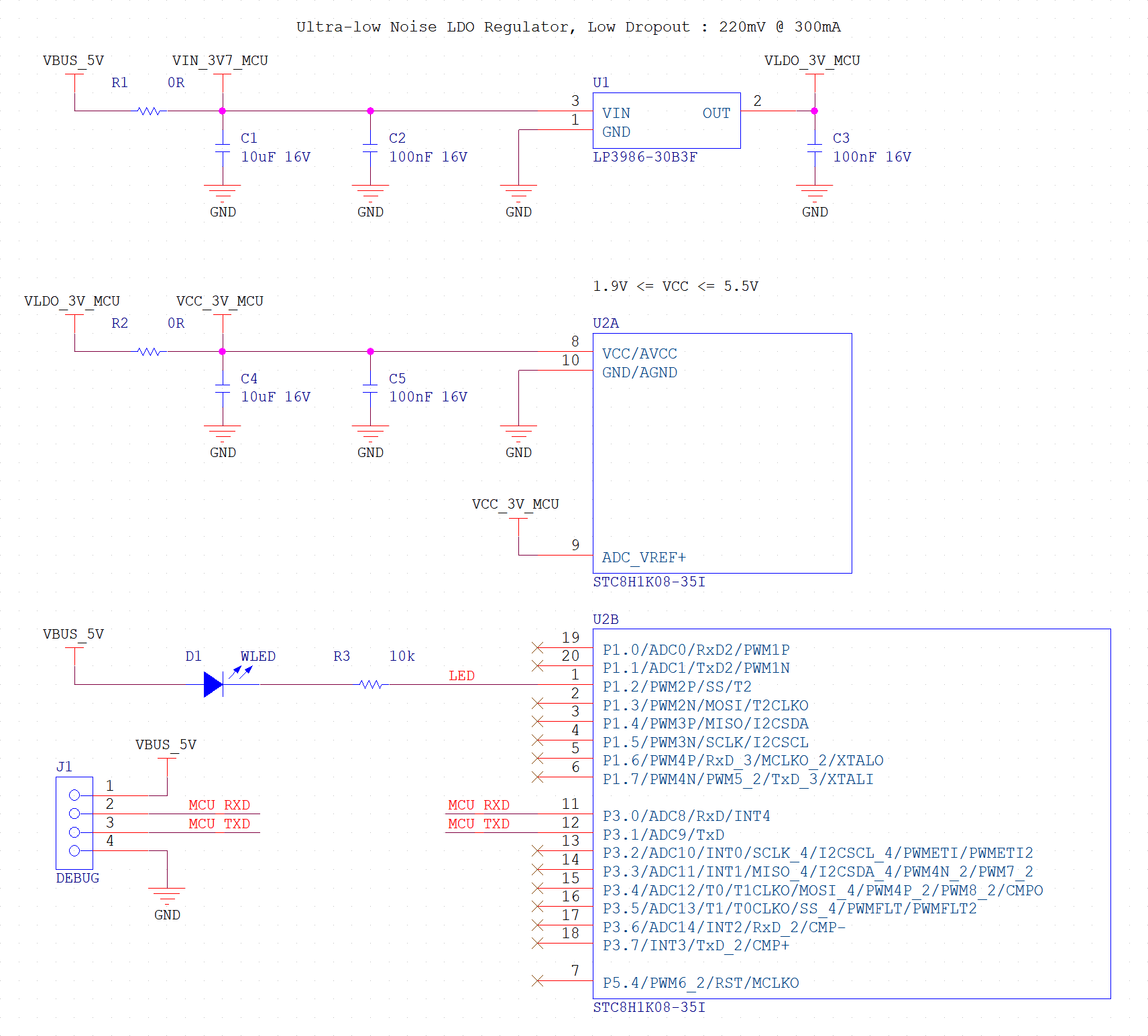
原理图:
main.c
/**
 * Interrupt Registers Definition
 */
sfr IE = 0xA8; /* Interrupt Enable Register */
sfr IE2 = 0xAF;

/**
 * Interrupt Registers Bits Definition
 */
/** IE */
#define GLOBAL_IE_EA    (0x80)
#define UART_IE_ES      (0x10)
/** IE2 */
#define T2_IE2_ET2      (0x04)


/**
 * Port Switch Register
 */
sfr P_SW2 = 0xBA;

/**
 * Port Switch Register Bits Definition
 */
#define P_SW2_EAXFR     (0x80)


/**
 * UART Registers Definition
 */
sfr SCON    = 0x98; /* Serial Control */
sfr SBUF    = 0x99; /* Serial Buffer */

/**
 * UART Registers Bits Definition
 */
/** SCON */
#define UART_SCON_SM0   (0x80) /* UART - Serial Mode Selection Bit 0 */
#define UART_SCON_SM1   (0x40) /* UART - Serial Mode Selection Bit 1 */
#define UART_SCON_REN   (0x10) /* UART - Receiver Enable */
#define UART_SCON_TI    (0x02) /* UART - Transmission Completion Interrupt */
#define UART_SCON_RI    (0x01) /* UART - Reception Completion Interrupt */

sbit TI = SCON^1;
sbit RI = SCON^0;


/**
 * Timer 2 Registers Definition
 */
#define TM2PS   (*(unsigned char volatile xdata *)0xFEA2) /* Timer 2 Prescaler Register */
sfr T2L         = 0xD7; /* Timer 2 Counter Low Register */
sfr T2H         = 0xD6; /* Timer 2 Counter High Register */


/**
 * Auxiliary Register Definition
 */
sfr AUXR        = 0x8E; /* Auxiliary Register */

/**
 * Auxiliary Register Bits Definition
 */
/** AUXR */
#define T2_AUXR_T2R     (0x10) /* Timer 1 - Run Control */
#define T2_AUXR_T2_CT   (0x08) /* Timer 1 - Counter or Timer Selection */
#define T2_AUXR_T2x12   (0x04) /* Timer 1 - Clock Divider Control */
#define UART_AUXR_S1ST2 (0x01) /* UART - Serial 1 (UART) Select Timer 2 Acts As Baud Rate Generator */


/**
 * Port 1 Registers Definition
 */
sfr P1      = 0x90; /* Port 1 Register */
sfr P1M1    = 0x91; /* Port 1 Configuration Register 1 */
sfr P1M0    = 0x92; /* Port 1 Configuration Register 0 */

/**
 * Port 1 Registers Bits Definition
 */
#define P12M1   (0x04) /* P1.2 - Mode Selection Bit 1 */
#define P12M0   (0x04) /* P1.2 - Mode Selection Bit 0 */


#define enableInterrupts()      IE |= GLOBAL_IE_EA
#define disableInterrupts()     IE &= ~GLOBAL_IE_EA


#define INTERNAL_RC_OSCILLATOR_FREQUENCY_11059200HZ (11059200UL) /* 11.0592 MHz */
#define INTERNAL_RC_OSCILLATOR_FREQUENCY_12000000HZ (12000000UL) /* 12.0000 MHz */

#define SYSTEM_CLOCK    (INTERNAL_RC_OSCILLATOR_FREQUENCY_11059200HZ)


#define UART_BAUD_RATE_9600 (9600L)

sbit LED = P1^2; /* LED Control Bit. 0: On, 1: Off */


/**
 * UART - Mode 1
 */
void main() {
    unsigned int prescaler = 0;
    unsigned int divider = 0;
    unsigned int timer = 0;


    /** UART Initialization */
    SCON &= ~UART_SCON_SM0;
    SCON |= UART_SCON_SM1;
    SCON |= UART_SCON_REN; // 允许 UART 接收
    SCON &= ~UART_SCON_TI; // 清除发送中断标志
    SCON &= ~UART_SCON_RI; // 清除接收中断标志
    AUXR |= UART_AUXR_S1ST2; // 选择 T2 作为波特率发生器
    IE |= UART_IE_ES; // 允许 UART1 请求中断

    /** Timer 2 Initialization */
    AUXR &= ~T2_AUXR_T2_CT; // T2 作为定时器(对内部系统时钟进行计数)
    P_SW2 |= P_SW2_EAXFR; // 允许访问位于扩展 RAM 区的特殊功能寄存器
    TM2PS = 1; // 对 T2 的时钟进行 1 分频。分频公式:系统时钟 ÷ (TM2PS + 1)
    prescaler = TM2PS + 1;
    P_SW2 &= ~P_SW2_EAXFR; // 禁止访问位于扩展 RAM 区的特殊功能寄存器
    AUXR |= T2_AUXR_T2x12; // 不分频 T2 的时钟
//    AUXR &= ~T2_AUXR_T2x12; // 对 T2 的时钟进行 12 分频
    divider = ((AUXR & T2_AUXR_T2x12) == T2_AUXR_T2x12) ? 1 : 12;
    timer = (65536 - SYSTEM_CLOCK / 4 / divider / prescaler / UART_BAUD_RATE_9600);
    T2H = timer >> 8;
    T2L = timer;
    IE2 &= T2_IE2_ET2; // 禁止 T2 请求中断
    AUXR |= T2_AUXR_T2R; // 允许 T2 开始计数

    /** IO Initialization */
    P1M1 &= ~P12M1;
    P1M0 |=  P12M0;

    enableInterrupts();

    while(1) {}
}

void uartInterruptService() interrupt 4 {
    unsigned char buffer;

    if(RI) {
        RI = 0;
        buffer = SBUF; // Get data
        SBUF = buffer; // Set data

        LED = !LED;
    }
    if(TI) {
        TI = 0;
    }
}
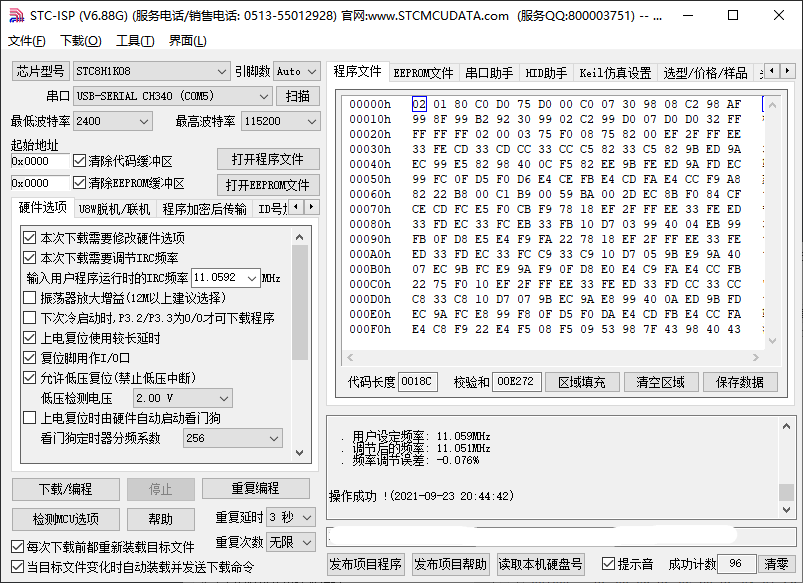
STC-ISP 的下载选项:
最后
以上就是丰富电脑最近收集整理的关于STC8H1K08 TSSOP20 - UART1 - Mode 1 - 使用 T2 做为波特率发生器的全部内容,更多相关STC8H1K08内容请搜索靠谱客的其他文章。
本图文内容来源于网友提供,作为学习参考使用,或来自网络收集整理,版权属于原作者所有。


发表评论 取消回复