CSI Framework
CSI-RS处理的总体过程可以看作是如下过程,本文将分别介绍CSI-RS CSI-Report CSI Codebook
- 配置/定义 CSI 参考信号的物理资源。参考 CSI-RS 章节 。
- 将一或多个 CSI-RS 组合到高层结构中,为了下一步目的。 参考 CSI-Report 章节。
- 定义/配置 上报原则 (上报周期、上报量、触发条件、码本配置等)。 上报周期、上报量、触发条件参考 CSI-Report 章节,码本配置参考 CSI Codebook 章节。
- UE按照网络的指示进行测量,并将测量结果上报给网络。
- 根据UE上报的测量结果,网络调整PHY/MAC参数,如MCS、天线配置、CSI码本等。
CSI-RS
NR CSI(Channel Status Information) 与LTE CSI相同,是UE测量多种信道质量并上报给gNB的机制。
CSI处理包含许多复杂的因素,本文主要关注CSI参考信号的生产和资源映射,其他内容在后续文章中介绍。
LTE中使用CRS,所以大多数情况下不需要CSI参考信号。从LTE TM9开始使用CSI-RS,如果你对此有所了解那么理解NR CSI-RS将会比较容易。
序列生成和资源映射
如下公式所示,NR CSI基于伪随机序列,此序列与特定的时域频域权重序列相乘,并经功率缩放因子缩放。然后此序列被映射到资源网格中一组RE中。完整过程总结如下,此过程包含许多参数。
如果你不是需要实现这部分的物理层工程师,你不需要了解全部细节,但是了解此过程中设计哪些参数(特别是RRC参数)是有好处的。
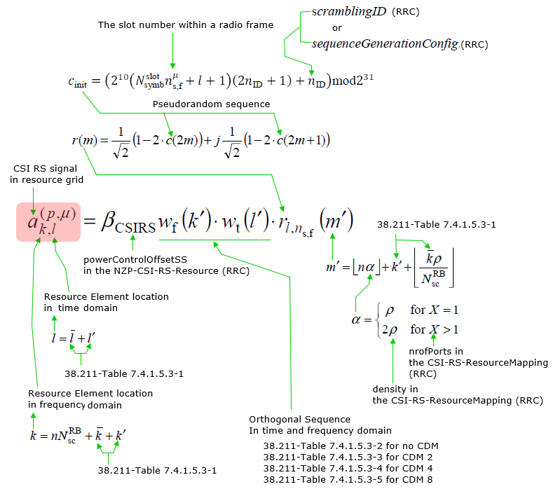
Resource Element 映射表
< 38.211-Table 7.4.1.5.3-1: CSI-RS locations within a slot. >
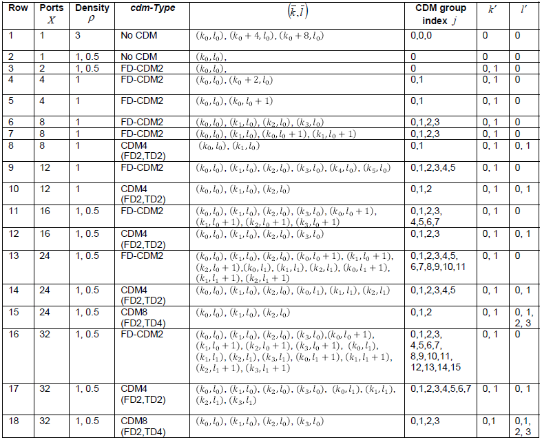
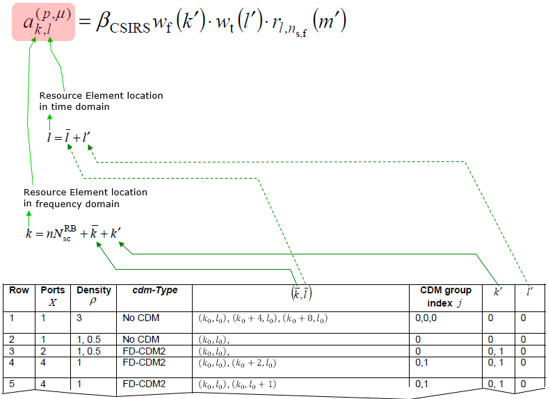
CSI-RS在时域上的参考位置由如下RRC参数决定。
-
 = CSI-RS-ResourceMapping.firstOFDMSymbolInTimeDomain
 -
 = CSI-RS-ResourceMapping.firstOFDMSymbolInTimeDomain2
CSI-RS在频域 (k1,k2,k3)上的参考位置由如下RRC参数决定。


f(i) 表示位图(CSI-RS-ResourceMapping.frequencyDomainAllocation)中第i个为1的值的位置 。每间隔density重复一次。
Ports, Density, cdm-Type 由如下RRC参数决定
- Ports = CSI-RS-ResourceMapping.nrofPorts
- cdm-Type = CSI-RS-ResourceMapping.cdm-Type
- Density = CSI-RS-ResourceMapping.density
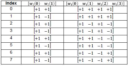
CDM 序列生成表
CDM表用于CSI-RS信号生成,如下所示。
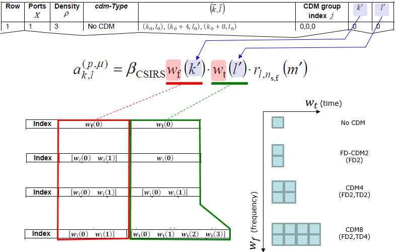
CDM表的每个元素值由38.211定义如下。
< 38.211 - Table 7.4.1.5.3-2: The sequences wf(k) f and wt(l) for cdm-Type equal to ‘no CDM’. >

< 38.211 - Table 7.4.1.5.3-3: The sequences wf(k) f and wt(l) for cdm-Type equal to ‘FD-CDM2’. >

< 38.211 - Table 7.4.1.5.3-4: The sequences wf(k) f and wt(l) for cdm-Type equal to ‘CDM4’. >
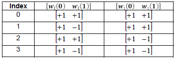
< 38.211 - Table 7.4.1.5.3-5: The sequences wf(k) f and wt(l) for cdm-Type equal to ‘CDM8’. >
NZP-CSI-RS-Resource配置解析
几乎所有本文介绍的内容都与resourceMapping参数有关,该参数位于NZP-CSI-RS-Resource配置下,如下所示。
NZP-CSI-RS-Resource ::= SEQUENCE {
nzp-CSI-RS-ResourceId NZP-CSI-RS-ResourceId,
resourceMapping CSI-RS-ResourceMapping,
powerControlOffset INTEGER (-8…15),
powerControlOffsetSS ENUMERATED{db-3, db0, db3, db6} OPTIONAL, – Need R
scramblingID ScramblingId,
periodicityAndOffset CSI-ResourcePeriodicityAndOffset OPTIONAL,-
qcl-InfoPeriodicCSI-RS TCI-StateId OPTIONAL, – Cond Periodic
…
}
resourceMapping :参考CSI-RS-ResourceMapping相关内容。
powerControlOffset : PDSCH RE 相对 NZP CSI-RS RE的功率偏移量,单位dB。
powerControlOffsetSS : NZP CSI-RS RE 相对 SSS RE的功率偏移量,单位dB。
qcl-InfoPeriodicCSI-RS : 对周期CSI-RS配置了TCI-State指示,配置了QCL source 和 QCL type。对周期CSI-RS而言,可以是SSB或者其他周期CSI-RS。对应小区对应DL BWP下PDSCH-Config的tci-StatesToAddModList配置中与tci-StateId相等的TCI-State。对目标周期CSI-RS提供QCL信息,源资源可以是SSB或者其他周期CSI-RS。
简而言之,指示了与CSI-TS满足QCL关系的tci-StateId。
UE如何知道使用哪个CSI-RS?(CSI-RS-ResourceMapping)
网络侧分配CSI-RS资源时只需要从38.211-Table 7.4.1.5.3-1表中选择一行并在对应RE上填上信号。但是UE如何能够确定gNB使用的是哪个CSI-RS?
gNB通过RRC消息将CSI-RS的详细配置通知给UE,具体包括哪些参数如下所述。
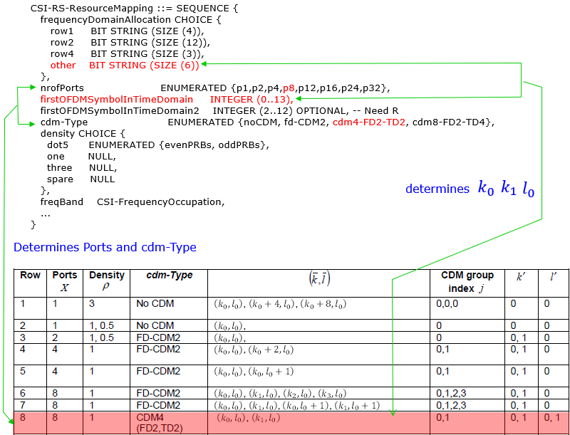
UE如何确定CSI-RS port 和 cdm配置?(38.211 Table 7.4.1.5.3-1 )
CSI-RS-ResourceMapping配置中通过nrofPorts和cdm-Type指示了端口号和码分类型,如下所示。
CSI-RS-ResourceMapping ::= SEQUENCE {
frequencyDomainAllocation CHOICE {
row1 BIT STRING (SIZE (4)),
row2 BIT STRING (SIZE (12)),
row4 BIT STRING (SIZE (3)),
other BIT STRING (SIZE (6))
},
nrofPorts ENUMERATED {p1,p2,p4,p8,p12,p16,p24,p32},
firstOFDMSymbolInTimeDomain INTEGER (0…13),
firstOFDMSymbolInTimeDomain2 INTEGER (2…12) OPTIONAL, – Need R
cdm-Type ENUMERATED {noCDM, fd-CDM2, cdm4-FD2-TD2, cdm8-FD2-TD4},
density CHOICE {
dot5 ENUMERATED {evenPRBs, oddPRBs},
one NULL,
three NULL,
spare NULL
},
freqBand CSI-FrequencyOccupation,
…
}
UE如何确定选定CSI-RS的REs(Resource Elements)?
下表中 (k_bar, l_bar)列结合CSI-RS-ResourceMapping中frequencyDomainAllocation和firstOFDMSymbolInTimeDomain配置即可确定占用的REs。

CSI-RS-ResourceMapping ::= SEQUENCE {
frequencyDomainAllocation CHOICE {
row1 BIT STRING (SIZE (4)),
row2 BIT STRING (SIZE (12)),
row4 BIT STRING (SIZE (3)),
other BIT STRING (SIZE (6))
},
nrofPorts ENUMERATED {p1,p2,p4,p8,p12,p16,p24,p32},
firstOFDMSymbolInTimeDomain INTEGER (0…13),
firstOFDMSymbolInTimeDomain2 INTEGER (2…12) OPTIONAL, – Need R
cdm-Type ENUMERATED {noCDM, fd-CDM2, cdm4-FD2-TD2, cdm8-FD2-TD4},
density CHOICE {
dot5 ENUMERATED {evenPRBs, oddPRBs},
one NULL,
three NULL,
spare NULL
},
freqBand CSI-FrequencyOccupation,
…
}
CSI-FrequencyOccupation ::= SEQUENCE {
startingRB INTEGER (0…maxNrofPhysicalResourceBlocks-1),
nrofRBs INTEGER (24…maxNrofPhysicalResourceBlocksPlus1),
…
}
startingRB : CSI资源起始PRB,相对于CRB#0位置,只能是4的整数倍。
nrofRBs : CSI资源占用的PRB个数,只能是4的整数倍。最小需要配置成min(24,BWP带宽)。如果配置值大于关联的BWP,UE认为实际CSI-RS占用数等于BWP带宽。
以上介绍的过程可以用下图表示。
UE如何确定使用哪种(逻辑)天线配置?
这部分内容参考CSI Codebook部分的介绍。
CSI RS资源映射案例
这部分包含多个CSI-RS的RRC配置实例。
CSI-RS-ResourceMapping ::= SEQUENCE {
frequencyDomainAllocation CHOICE {
row1 BIT STRING (SIZE (4)),
row2 BIT STRING (SIZE (12)),
row4 BIT STRING (SIZE (3)),
other BIT STRING (SIZE (6))
},
nrofPorts ENUMERATED {p1,p2,p4,p8,p12,p16,p24,p32},
firstOFDMSymbolInTimeDomain INTEGER (0…13),
firstOFDMSymbolInTimeDomain2 INTEGER (2…12) OPTIONAL, – Need R
cdm-Type ENUMERATED {noCDM, fd-CDM2, cdm4-FD2-TD2, cdm8-FD2-TD4},
density CHOICE {
dot5 ENUMERATED {evenPRBs, oddPRBs},
one NULL,
three NULL,
spare NULL
},
freqBand CSI-FrequencyOccupation,
…
}
以下是一些确定REs在PRB中位置的例子,因为这些例子只在单个RB中,所以在计算k值的等式中忽略了 n N^RB_sc这一项。
Example 01 >
当RRC参数配置如下,
-
density = three
-
nrofPorts = p1
-
cdm-Type = noCDM
-
frequencyDomainAllocation.row1 = 0001
-
firstOFDMSymbolinTimeDomain = 4
根据38.211-Table 7.4.1.5.3-1,


-
k prime = {0} ==> k prime[0] = 0
-
l prime = {0} ==> l prime[0] = 0
根据参数
-
k0 = 0 (根据frequencyDomainAllocation.row1 = 0001)
-
l0 = 4(根据firstOFDMSymbolinTimeDomain = 4)
根据以上信息,查表 38.211-Table 7.4.1.5.3-1,
-
(k,l) = (k0+kprim[0],l0+lprim[0]) ,(k0+4+kprim[0],l0+lprim[0]) ,(k0+8+kprim[0],l0+lprim[0])
-
= (0+0,4+0) ,(0+4+0,4+0) ,(0+8+0,4+0)
-
= (0,4) ,(4,4) ,(8,4)
| 0 | 1 | 2 | 3 | 4 | 5 | 6 | 7 | 8 | 9 | 10 | 11 | 12 | 13 | |
|---|---|---|---|---|---|---|---|---|---|---|---|---|---|---|
| 11 | ||||||||||||||
| 10 | ||||||||||||||
| 9 | ||||||||||||||
| 8 | √ | |||||||||||||
| 7 | ||||||||||||||
| 6 | ||||||||||||||
| 5 | ||||||||||||||
| 4 | √ | |||||||||||||
| 3 | ||||||||||||||
| 2 | ||||||||||||||
| 1 | ||||||||||||||
| 0 | √ |
Example 02 >
当RRC参数配置如下,
-
density = three
-
nrofPorts = p1
-
cdm-Type = noCDM
-
frequencyDomainAllocation.row1 = 0100
-
firstOFDMSymbolinTimeDomain = 4
根据38.211-Table 7.4.1.5.3-1,


-
k prime = {0} ==> k prime[0] = 0
-
l prime = {0} ==> l prime[0] = 0
根据RRC参数,
-
k0 = 2 (based on frequencyDomainAllocation.row1 = 0100)
-
l0 = 4(based on firstOFDMSymbolinTimeDomain = 4)
根据以上信息,查表 38.211-Table 7.4.1.5.3-1,
-
(k,l) = (k0+kprim[0],l0+lprim[0]) ,(k0+4+kprim[0],l0+lprim[0]) ,(k0+8+kprim[0],l0+lprim[0])
-
= (2+0,4+0) ,(2+4+0,4+0) ,(2+8+0,4+0)
-
= (2,4) ,(6,4) ,(10,4)
| 0 | 1 | 2 | 3 | 4 | 5 | 6 | 7 | 8 | 9 | 10 | 11 | 12 | 13 | |
|---|---|---|---|---|---|---|---|---|---|---|---|---|---|---|
| 11 | ||||||||||||||
| 10 | √ | |||||||||||||
| 9 | ||||||||||||||
| 8 | ||||||||||||||
| 7 | ||||||||||||||
| 6 | √ | |||||||||||||
| 5 | ||||||||||||||
| 4 | ||||||||||||||
| 3 | ||||||||||||||
| 2 | √ | |||||||||||||
| 1 | ||||||||||||||
| 0 |
Example 03 >
当RRC参数配置如下, (这个例子参考TRS案例 38.508-1 Table 4.6.3-45: CSI-RS-ResourceMapping)
-
density = three
-
nrofPorts = p1
-
cdm-Type = noCDM
-
frequencyDomainAllocation.row1 = 1000 // From density,nrofPorts we can guess that this is for row1.
-
firstOFDMSymbolinTimeDomain = 4
根据38.211-Table 7.4.1.5.3-1,


-
k prime = {0} ==> k prime[0] = 0
-
l prime = {0} ==> l prime[0] = 0
根据RRC配置,
-
k0 = 3 (based on frequencyDomainAllocation.row1 = 1000)
-
l0 = 4(based on firstOFDMSymbolinTimeDomain = 4)
根据以上信息,查表 38.211-Table 7.4.1.5.3-1,
-
(k,l) = (k0+kprim[0],l0+lprim[0]) ,(k0+4+kprim[0],l0+lprim[0]) ,(k0+8+kprim[0],l0+lprim[0])
-
= (3+0,4+0) ,(3+4+0,4+0) ,(3+8+0,4+0)
-
= (3,4) ,(7,4) ,(11,4)
| 0 | 1 | 2 | 3 | 4 | 5 | 6 | 7 | 8 | 9 | 10 | 11 | 12 | 13 | |
|---|---|---|---|---|---|---|---|---|---|---|---|---|---|---|
| 11 | √ | |||||||||||||
| 10 | ||||||||||||||
| 9 | ||||||||||||||
| 8 | ||||||||||||||
| 7 | √ | |||||||||||||
| 6 | ||||||||||||||
| 5 | ||||||||||||||
| 4 | ||||||||||||||
| 3 | √ | |||||||||||||
| 2 | ||||||||||||||
| 1 | ||||||||||||||
| 0 |
Example 04 >
当RRC参数配置如下,
-
density = one
-
nrofPorts = p1
-
cdm-Type = noCDM
-
frequencyDomainAllocation.row2 = 010000000000
-
firstOFDMSymbolinTimeDomain = 13
根据38.211-Table 7.4.1.5.3-1,


-
k prime = {0} ==> k prime[0] = 0
-
l prime = {0} ==> l prime[0] = 0
根据RRC配置,
-
k0 = 10 (based on frequencyDomainAllocation.row2 = 010000000000)
-
l0 = 13(based on firstOFDMSymbolinTimeDomain = 13)
根据以上信息,查表 38.211-Table 7.4.1.5.3-1,
-
(k,l) = (k0+kprim[0],l0+lprim[0])
-
= (10+0,13+0)
-
= (10,13)
| 0 | 1 | 2 | 3 | 4 | 5 | 6 | 7 | 8 | 9 | 10 | 11 | 12 | 13 | |
|---|---|---|---|---|---|---|---|---|---|---|---|---|---|---|
| 11 | ||||||||||||||
| 10 | √ | |||||||||||||
| 9 | ||||||||||||||
| 8 | ||||||||||||||
| 7 | ||||||||||||||
| 6 | ||||||||||||||
| 5 | ||||||||||||||
| 4 | ||||||||||||||
| 3 | ||||||||||||||
| 2 | ||||||||||||||
| 1 | ||||||||||||||
| 0 |
Example 05 >
当RRC参数配置如下,
-
density = one
-
nrofPorts = p2
-
cdm-Type = FD-CDM2
-
frequencyDomainAllocation.other = 001000
-
firstOFDMSymbolinTimeDomain = 13
-
Assume that row = 3 (you need additional information to determine the row number other than 1,2,4. In this example, it is given)
根据38.211-Table 7.4.1.5.3-1,


-
k prime = {0,1} ==> k prime[0] = 0, k prime[1] = 1
-
l prime = {0} ==> l prime[0] = 0
根据RRC配置,
-
k0 = 2 x 3(bit position) = 6 (based on frequencyDomainAllocation.other = 001000)
-
l0 = 13(based on firstOFDMSymbolinTimeDomain = 13)
根据以上信息,查表 38.211-Table 7.4.1.5.3-1,
-
(k,l) = (k0+kprim[0],l0+lprim[0]),(k0+kprim[1],l0+lprim[0])
-
= (6+0,13+0),(6+1,13+0)
-
= (6,13),(7,13)
| 0 | 1 | 2 | 3 | 4 | 5 | 6 | 7 | 8 | 9 | 10 | 11 | 12 | 13 | |
|---|---|---|---|---|---|---|---|---|---|---|---|---|---|---|
| 11 | ||||||||||||||
| 10 | ||||||||||||||
| 9 | ||||||||||||||
| 8 | ||||||||||||||
| 7 | wf(1) | |||||||||||||
| 6 | wf(0) | |||||||||||||
| 5 | ||||||||||||||
| 4 | ||||||||||||||
| 3 | ||||||||||||||
| 2 | ||||||||||||||
| 1 | ||||||||||||||
| 0 |
Example 06 >
当RRC参数配置如下, (此例子基于FR1案例 38.508-1 Table 4.6.3-45: CSI-RS-ResourceMapping)
-
density = one
-
nrofPorts = p8
-
cdm-Type = fd-CDM2
-
frequencyDomainAllocation.other = 011110 //From density,nrofPorts,cdm-Tye it is assumed that this is for row6.
-
firstOFDMSymbolinTimeDomain = 3
根据38.211-Table 7.4.1.5.3-1,


-
k prime = {0,1} ==> k prime[0] = 0, k prime[1] = 1
-
l prime = {0} ==> l prime[0] = 0
根据RRC参数,
-
k0 = 2 (based on frequencyDomainAllocation.other = 011110)
-
k1 = 4 (based on frequencyDomainAllocation.other = 011110)
-
k2 = 6 (based on frequencyDomainAllocation.other = 011110)
-
k3 = 8 (based on frequencyDomainAllocation.other = 011110)
-
l0 = 3(based on firstOFDMSymbolinTimeDomain = 3)
根据以上信息,查表 38.211-Table 7.4.1.5.3-1,
-
(k,l) = (k0+kprim[0],l0+lprim[0]) ,(k1+kprim[0],l0+lprim[0]) ,(k2+kprim[0],l0+lprim[0]), (k3+kprim[0],l0+lprim[0])
-
(k0+kprim[1],l0+lprim[0]) ,(k1+kprim[1],l0+lprim[0]) ,(k2+kprim[1],l0+lprim[0]), (k3+kprim[1],l0+lprim[0])
-
= (2+0,3+0) ,(4+0,3+0) ,(6+0,3+0),(8+0,3+0),(2+1,3+0) ,(4+1,3+0) ,(6+1,3+0),(8+1,3+0)
-
= (2,3) ,(4,3) ,(6,3) ,(8,3), (3,3) ,(5,3) ,(7,3) ,(9,3)
| 0 | 1 | 2 | 3 | 4 | 5 | 6 | 7 | 8 | 9 | 10 | 11 | 12 | 13 | |
|---|---|---|---|---|---|---|---|---|---|---|---|---|---|---|
| 11 | ||||||||||||||
| 10 | ||||||||||||||
| 9 | wf(1) | |||||||||||||
| 8 | wf(0) | |||||||||||||
| 7 | wf(1) | |||||||||||||
| 6 | wf(0) | |||||||||||||
| 5 | wf(1) | |||||||||||||
| 4 | wf(0) | |||||||||||||
| 3 | wf(1) | |||||||||||||
| 2 | wf(0) | |||||||||||||
| 1 | ||||||||||||||
| 0 |
NOTE : 以上资源映射方式展示了CSI-RS所有天线端口(此处为8端口)叠加在同一资源网格。实际传输过程中,这些分为8个CSI-RS端口,每个CSI-RS端口如何区分在38.211 section 7.4.1.5.3中定义。在本例中按照协议定义天线端口分布如下。
本例使用的是FD-CDM2,所以’s’由下表的索引决定,'L’为2(CDM组大小)。N为8(CSI-RS端口数)。
< 38.211 - Table 7.4.1.5.3-3: The sequences wf(k) f and wt(l) for cdm-Type equal to ‘FD-CDM2’. >

根据以上信息, j 和s 为以下值,
-
s = 0,1 (index of Table 7.4.1.5.3-3)
-
j = 0,1,…,N/L-1 = 0,1,…,(8/2-1) = 0,1,2,3
计算天线端口号如下,
-
p = 3000 + s + j L , where s = {0,1}, j = {0,1,2,3}
-
= 3000 + {0,1} + {0,1,2,3} 2
-
= {3000, 3002, 3004, 3006, 3001, 3003, 3005, 3007}
NOTE : 本例每端口资源映射的Matlab仿真结果请看this note.
Example 07 >
当RRC参数配置如下, (此例子基于FR1案例 38.508-1 Table 4.6.3-45: CSI-RS-ResourceMapping)
-
density = one
-
nrofPorts = p8
-
cdm-Type = fd-CDM2
-
frequencyDomainAllocation.other = 000110 //From density,nrofPorts,cdm-Tye it is assumed that this is for row7.
-
firstOFDMSymbolinTimeDomain = 3
根据38.211-Table 7.4.1.5.3-1,


-
k prime = {0,1} ==> k prime[0] = 0, k prime[1] = 1
-
l prime = {0} ==> l prime[0] = 0
根据RRC配置,
-
k0 = 2 (based on frequencyDomainAllocation.other = 000110)
-
k1 = 4 (based on frequencyDomainAllocation.other = 000110)
-
l0 = 3(based on firstOFDMSymbolinTimeDomain = 3)
根据以上信息,查表 38.211-Table 7.4.1.5.3-1,
-
(k,l) = (k0+kprim[0],l0+lprim[0]) ,(k1+kprim[0],l0+lprim[0]) ,
-
(k0+kprim[0],l0+lprim[0]+1), (k1+kprim[0],l0+lprim[0]+1)
-
(k0+kprim[1],l0+lprim[0]) ,(k1+kprim[1],l0+lprim[0]) ,
-
(k0+kprim[1],l0+lprim[0]+1), (k1+kprim[1],l0+lprim[0]+1)
-
= (2+0,3+0) ,(4+0,3+0) ,(2+0,3+0+1) ,(4+0,3+0+1),(2+1,3+0) ,(4+1,3+0) ,(2+1,3+0+1) ,(4+1,3+0+1)
-
= (2,3) ,(4,3) ,(2,4),(4,4),(3,3),(5,3),(3,4),(5,4)
| 0 | 1 | 2 | 3 | 4 | 5 | 6 | 7 | 8 | 9 | 10 | 11 | 12 | 13 | |
|---|---|---|---|---|---|---|---|---|---|---|---|---|---|---|
| 11 | ||||||||||||||
| 10 | ||||||||||||||
| 9 | ||||||||||||||
| 8 | ||||||||||||||
| 7 | ||||||||||||||
| 6 | ||||||||||||||
| 5 | wf(1) | wf(1) | ||||||||||||
| 4 | wf(0) | wf(0) | ||||||||||||
| 3 | wf(1) | wf(1) | ||||||||||||
| 2 | wf(0) | wf(0) | ||||||||||||
| 1 | ||||||||||||||
| 0 |
NOTE : The above resource mapping is showing the CSI-RS for all antenna ports (8 ports in this case) superimposed in one resource grid. In real transmission, these resources are devided among the 8 CSI-RS antenna ports. How they are splitted among each CSI-RS antenna port is specified in 38.211 section 7.4.1.5.3. Applying the logic in the spec to this example, the antenna port distribution become as follows.
Since this example is using FD-CDM2, it is assumed that ‘s’ is determined by the index value of the following table and ‘L’ becomes 2. N is given in this example (38.211-Table 7.4.1.5.3-1) is 8.
< 38.211 - Table 7.4.1.5.3-3: The sequences wf(k) f and wt(l) for cdm-Type equal to ‘FD-CDM2’. >

Based on this information, j and s can be calculated as follows.
-
s = 0,1 (index of Table 7.4.1.5.3-3)
-
j = 0,1,…,N/L-1 = 0,1,…,(8/2-1) = 0,1,2,3
Now we can calculate the antenna port as follows.
-
p = 3000 + s + j L , where s = {0,1}, j = {0,1,2,3}
-
= 3000 + {0,1} + {0,1,2,3} 2
-
= {3000, 3002, 3004, 3006, 3001, 3003, 3005, 3007}
NOTE : I posted Matlab simulation for this case showing the resource mapping for each antenna port on this note.
Example 08 >
Given the following RRC parameters, (this example is based on FR1 case in 38.508-1 Table 4.6.3-45: CSI-RS-ResourceMapping)
-
density = one
-
nrofPorts = p8
-
cdm-Type = CDM4(FD2,TD2)
-
frequencyDomainAllocation.other = 000110 //From density,nrofPorts,cdm-Tye it is assumed that this is for row8.
-
firstOFDMSymbolinTimeDomain = 3
According to 38.211-Table 7.4.1.5.3-1,


-
k prime = {0,1} ==> k prime[0] = 0, k prime[1] = 1
-
l prime = {0,1} ==> l prime[0] = 0, l prime[1] = 1
According to the given, RRC parameters
-
k0 = 2 (based on frequencyDomainAllocation.other = 000110)
-
k1 = 4 (based on frequencyDomainAllocation.other = 000110)
-
l0 = 3(based on firstOFDMSymbolinTimeDomain = 3)
Based on all these information and , we get 38.211-Table 7.4.1.5.3-1,
-
(k,l) = (k0+kprim[0],l0+lprim[0]) ,(k1+kprim[0],l0+lprim[0]),
-
(k0+kprim[1],l0+lprim[0]) ,(k1+kprim[1],l0+lprim[0]),
-
(k0+kprim[0],l0+lprim[1]) ,(k1+kprim[0],l0+lprim[1]),
-
(k0+kprim[1],l0+lprim[1]) ,(k1+kprim[1],l0+lprim[1]),
-
= (2+0,3+0) ,(4+0,3+0) ,(2+1,3+0) ,(4+1,3+0),(2+0,3+1) ,(4+0,3+1) ,(2+1,3+1) ,(4+1,3+1)
-
= (2,3) ,(4,3) ,(3,3),(5,3),(2,4),(4,4),(3,4),(5,4)
| 0 | 1 | 2 | 3 | 4 | 5 | 6 | 7 | 8 | 9 | 10 | 11 | 12 | 13 | |
|---|---|---|---|---|---|---|---|---|---|---|---|---|---|---|
| 11 | ||||||||||||||
| 10 | ||||||||||||||
| 9 | ||||||||||||||
| 8 | ||||||||||||||
| 7 | ||||||||||||||
| 6 | ||||||||||||||
| 5 | wft1 | wft1 | ||||||||||||
| 4 | wft0 | wft0 | ||||||||||||
| 3 | wft1 | wft1 | ||||||||||||
| 2 | wft0 | wft0 | ||||||||||||
| 1 | ||||||||||||||
| 0 |
NOTE : wft0 = wf(0) wt(0), wft1 = wf(1) wt(1)
NOTE : The above resource mapping is showing the CSI-RS for all antenna ports (8 ports in this case) superimposed in one resource grid. In real transmission, these resources are devided among the 8 CSI-RS antenna ports. How they are splitted among each CSI-RS antenna port is specified in 38.211 section 7.4.1.5.3. Applying the logic in the spec to this example, the antenna port distribution become as follows.
Since this example is using FD-CDM2, it is assumed that ‘s’ is determined by the index value of the following table and ‘L’ becomes 4. N is given in this example (38.211-Table 7.4.1.5.3-1) is 8.
< 38.211 - Table 7.4.1.5.3-4: The sequences wf(k) f and wt(l) for cdm-Type equal to ‘CDM4’. >
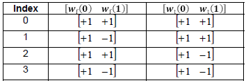
Based on this information, j and s can be calculated as follows.
-
s = 0,1,2,3 (index of Table 7.4.1.5.3-4)
-
j = 0,1,…,N/L-1 = 0,1,…,(8/4-1) = 0,1
Now we can calculate the antenna port as follows.
-
p = 3000 + s + j L , where s = {0,1}, j = {0,1,2,3}
-
= 3000 + {0,1,2,3} + {0,1} 4
-
= {3000, 3004, 3004, 3006, 3001, 3003, 3005, 3007}
NOTE : I posted Matlab simulation for this case showing the resource mapping for each antenna port on this note.
CSI RS 传输时机
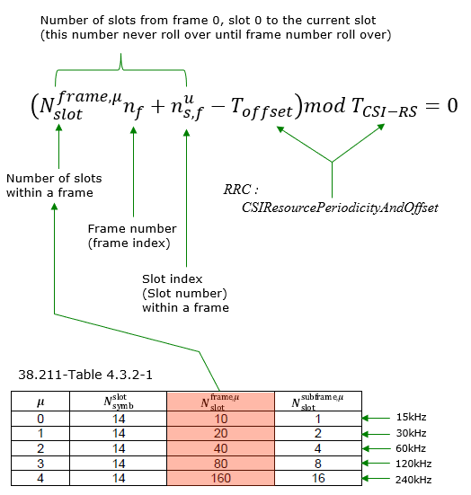
CSI 传输时机通过RRC参数CSI-ResourcePeriodicityAndOffset配置,由以下公式计算得出。
测量干扰的资源 (CSI-IM)
CSI IM资源是预留的一组用来测量干扰的REs。通过RRC参数配置,时频域位置配置参考38.214 - 5.2.2.4描述如下。
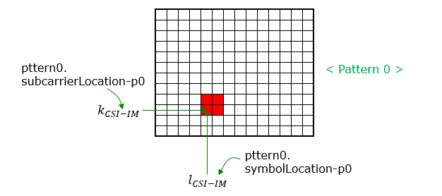
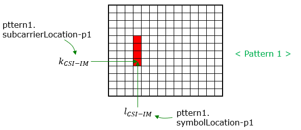
CSI-IM-Resource ::= SEQUENCE {
csi-IM-ResourceId CSI-IM-ResourceId,
csi-IM-ResourceElementPattern CHOICE {
pattern0 SEQUENCE {
subcarrierLocation-p0 ENUMERATED { s0, s2, s4, s6, s8, s10 },
symbolLocation-p0 INTEGER (0…12)
},
pattern1 SEQUENCE {
subcarrierLocation-p1 ENUMERATED { s0, s4, s8 },
symbolLocation-p1 INTEGER (0…13)
}
} OPTIONAL, – Need M
freqBand CSI-FrequencyOccupation OPTIONAL,
periodicityAndOffset CSI-ResourcePeriodicityAndOffset OPTIONAL,
PeriodicOrSemiPersistent
…
}
pattern 0 / pattern1 :如上图所示。
CSI-FrequencOccupation ::= SEQUENCE {
startingRB INTEGER (0…maxNrofPhysicalResourceBlocks-1),
nrofRBs INTEGER (24…maxNrofPhysicalResourceBlocksPlus1),
…
}
startingRB : CSI资源起始PRB,相对于CRB#0位置,只能是4的整数倍。
nrofRBs : CSI资源占用的PRB个数,只能是4的整数倍。最小需要配置成min(24,BWP带宽)。如果配置值大于关联的BWP,UE认为实际CSI-RS占用数等于BWP带宽。
跟踪参考信号 (TRS)
NZP-CSI-RS-ResourceSet ::= SEQUENCE {
nzp-CSI-ResourceSetId NZP-CSI-RS-ResourceSetId,
nzp-CSI-RS-Resources SEQUENCE (SIZE (1…maxNrofNZP-CSI-RS-ResourcesPerSet))
OF NZP-CSI-RS-ResourceId,
repetition ENUMERATED { on, off } OPTIONAL,
aperiodicTriggeringOffset INTEGER(0…4) OPTIONAL,
trs-Info ENUMERATED {true} OPTIONAL,
…
}
38.331 定义 trs-Info 如下。
trs-Info : Indicates that the antenna port for all NZP-CSI-RS resources in the CSI-RS resource set is same. If the field is absent or released the UE applies the value false
指示此 CSI-RS资源集下的所有NZP-CSI-RS资源有相同的天线端口。如果该字段不存在或被释放,UE认为值为false。
38.214-5.2.2.3.1 解释如下:
trs-Info in NZP-CSI-RS-ResourceSet is associated with a CSI-RS resource set and for which the UE can assume that the antenna port with the same port index of the configured NZP CSI-RS resources in the NZP-CSI-RSResourceSet is the same as described in Subclause 5.1.6.1.1 and can be configured when reporting setting is not configured or when the higher layer parameter reportQuantity associated with all the reporting settings linked with the CSI-RS resource set is set to ‘none’.
38.214-5.1.6.1.1 指定了多个csi-rs如何组成一个trs,如下:
For a NZP-CSI-RS-ResourceSet configured with the higher layer parameter trs-Info, the UE shall assume the antenna
port with the same port index of the configured NZP CSI-RS resources in the NZP-CSI-RS-ResourceSet is the same. For frequency range 1(FR1), the UE may be configured with one or more NZP CSI-RS set(s), where a NZP-CSI-RS-ResourceSet consists of four periodic NZP CSI-RS resources in two consecutive slots with two periodic NZP CSI-RS resources in each slot.
For frequency range 2(FR2) the UE may be configured with one or more NZP CSI-RS set(s), where a NZP-CSI-RSResourceSet consists of two periodic CSI-RS resources in one slot or with a NZP-CSI-RS-ResourceSet of four periodic NZP CSI-RS resources in two consecutive slots with two periodic NZP CSI-RS resources in each slot.
NOTE : trs-info的设置影响适用QCL的类型,参考 this note。
CSI RS的RRC配置参数
配置CSI-RS的层次较为复杂,总体上可以分为以下几个层次。
-
i) 配置CSI-RS在单RB内RE的位置,见 CSI-RS-ResourceMapping
-
ii) 配置频域上RB位置(起始RB位置和RB个数),见 CSI-RS-ResourceMapping.freqBand
-
iii) 配置时域上的周期与偏移,见 ZP-CSI-RS-Resource / NZP-CSI-RS-Resource
-
iv) 应用以上配置(i, ii, iii) ,见 PDSCH-Config or/and CSI-MeasConfig
PDSCH-Config ::=
SEQUENCE {
dataScramblingIdentityPDSCH
INTEGER (0..1007)
OPTIONAL,
dmrs-DownlinkForPDSCH-MappingTypeA
SetupRelease { DMRS-DownlinkConfig } OPTIONAL,
dmrs-DownlinkForPDSCH-MappingTypeB
SetupRelease { DMRS-DownlinkConfig }
OPTIONAL,
tci-StatesToAddModList
SEQUENCE (SIZE(1..maxNrofTCI-States)) OF TCI-State
OPTIONAL,
-- Need N
tci-StatesToReleaseList
SEQUENCE (SIZE(1..maxNrofTCI-States)) OF TCI-StateId OPTIONAL,
-- Need N
vrb-ToPRB-Interleaver
ENUMERATED {n2, n4},
resourceAllocation
ENUMERATED { resourceAllocationType0, resourceAllocationType1, dynamicSwitch},
pdsch-AllocationList
SEQUENCE (SIZE(1..maxNrofDL-Allocations)) OF PDSCH-TimeDomainResourceAllocation ,
pdsch-AggregationFactor
ENUMERATED { n2, n4, n8 } OPTIONAL,
rateMatchPatternToAddModList
SEQUENCE (SIZE (1..maxNrofRateMatchPatterns)) OF RateMatchPattern
OPTIONAL, -- Need N
rateMatchPatternToReleaseList
SEQUENCE (SIZE (1..maxNrofRateMatchPatterns)) OF RateMatchPatternId
OPTIONAL, -- Need N
rateMatchPatternGroup1
SEQUENCE (SIZE (1..maxNrofRateMatchPatterns)) OF RateMatchPatternId
OPTIONAL, -- Need R
rateMatchPatternGroup2
SEQUENCE (SIZE (1..maxNrofRateMatchPatterns)) OF RateMatchPatternId
OPTIONAL, -- Need R
rbg-Size
ENUMERATED {config1, config2},
mcs-Table
ENUMERATED {qam64, qam256},
maxNrofCodeWordsScheduledByDCI
ENUMERATED {n1, n2} OPTIONAL,
-- Need R
prb-BundlingType
CHOICE {
static
SEQUENCE {
bundleSize
ENUMERATED { n4, wideband } OPTIONAL
},
dynamic
SEQUENCE {
bundleSizeSet1
ENUMERATED { n4,
wideband,
n2-wideband,
n4-wideband
} OPTIONAL,
-- Need S
bundleSizeSet2
ENUMERATED { n4,
wideband
} OPTIONAL
-- Need S
}
},
zp-CSI-RS-ResourceToAddModList
SEQUENCE (SIZE (1..maxNrofZP-CSI-RS-Resources))
OF ZP-CSI-RS-Resource
OPTIONAL,
-- Need N
zp-CSI-RS-ResourceToReleaseList
SEQUENCE (SIZE (1..maxNrofZP-CSI-RS-Resources))
OF ZP-CSI-RS-ResourceId OPTIONAL,
-- Need M
aperiodic-ZP-CSI-RS-ResourceSetsToAddModList
SEQUENCE (SIZE (1..maxNrofZP-CSI-RS-Sets))
OF ZP-CSI-RS-ResourceSet OPTIONAL, -- Need N
aperiodic-ZP-CSI-RS-ResourceSetsToReleaseList
SEQUENCE (SIZE (1..maxNrofZP-CSI-RS-Sets))
OF ZP-CSI-RS-ResourceSetId
OPTIONAL, -- Need N
sp-ZP-CSI-RS-ResourceSetsToAddModList
SEQUENCE (SIZE (1..maxNrofZP-CSI-RS-Sets))
OF ZP-CSI-RS-ResourceSet
OPTIONAL, -- Need N
sp-ZP-CSI-RS-ResourceSetsToReleaseList SEQUENCE (SIZE (1..maxNrofZP-CSI-RS-Sets))
OF ZP-CSI-RS-ResourceSetId
OPTIONAL, -- Need N
...
}
CSI-MeasConfig ::= SEQUENCE {
nzp-CSI-RS-ResourceToAddModList
SEQUENCE (SIZE (1..maxNrofNZP-CSI-RS-Resources))
OF NZP-CSI-RS-Resource OPTIONAL,
nzp-CSI-RS-ResourceToReleaseList
SEQUENCE (SIZE (1..maxNrofNZP-CSI-RS-Resources))
OF NZP-CSI-RS-ResourceId OPTIONAL,
nzp-CSI-RS-ResourceSetToAddModList
SEQUENCE (SIZE (1..maxNrofNZP-CSI-RS-ResourceSets))
OF NZP-CSI-RS-ResourceSet OPTIONAL,
nzp-CSI-RS-ResourceSetToReleaseList
SEQUENCE (SIZE (1..maxNrofNZP-CSI-RS-ResourceSets))
OF NZP-CSI-RS-ResourceSetId OPTIONAL,
csi-IM-ResourceToAddModList
SEQUENCE (SIZE (1..maxNrofCSI-IM-Resources))
OF CSI-IM-Resource OPTIONAL,
csi-IM-ResourceToReleaseList
SEQUENCE (SIZE (1..maxNrofCSI-IM-Resources))
OF CSI-IM-ResourceId OPTIONAL,
csi-IM-ResourceSetToAddModList
SEQUENCE (SIZE (1..maxNrofCSI-IM-ResourceSets))
OF CSI-IM-ResourceSet OPTIONAL,
csi-IM-ResourceSetToReleaseList
SEQUENCE (SIZE (1..maxNrofCSI-IM-ResourceSets))
OF CSI-IM-ResourceSetId OPTIONAL,
csi-SSB-ResourceSetToAddModList
SEQUENCE (SIZE (1..maxNrofCSI-SSB-ResourceSets))
OF CSI-SSB-ResourceSet OPTIONAL,
csi-SSB-ResourceSetToAddReleaseList
SEQUENCE (SIZE (1..maxNrofCSI-SSB-ResourceSets))
OF CSI-SSB-ResourceSetId OPTIONAL,
csi-ResourceConfigToAddModList
SEQUENCE (SIZE (1..maxNrofCSI-ResourceConfigurations))
OF CSI-ResourceConfig OPTIONAL,
csi-ResourceConfigToReleaseList
SEQUENCE (SIZE (1..maxNrofCSI-ResourceConfigurations))
OF CSI-ResourceConfigId OPTIONAL,
csi-ReportConfigToAddModList
SEQUENCE (SIZE (1..maxNrofCSI-ReportConfigurations))
OF CSI-ReportConfig OPTIONAL,
csi-ReportConfigToReleaseList
SEQUENCE (SIZE (1..maxNrofCSI-ReportConfigurations))
OF CSI-ReportConfigId OPTIONAL,
reportTriggerSize
INTEGER (0..6) OPTIONAL,
aperiodicTriggerStateList
SetupRelease { CSI-AperiodicTriggerStateList },
semiPersistentOnPUSCH-TriggerStateList
SetupRelease {
CSI-SemiPersistentOnPUSCH-TriggerStateList
} OPTIONAL,
...
}
ZP-CSI-RS-Resource ::= SEQUENCE {
zp-CSI-RS-ResourceId
ZP-CSI-RS-ResourceId,
resourceMapping
CSI-RS-ResourceMapping,
periodicityAndOffset
CSI-ResourcePeriodicityAndOffset OPTIONAL,
...
}
ZP-CSI-RS-ResourceSet ::= SEQUENCE {
zp-CSI-RS-ResourceSetId
ZP-CSI-RS-ResourceSetId,
zp-CSI-RS-ResourceIdList
SEQUENCE (SIZE(1..maxNrofZP-CSI-RS-ResourcesPerSet)) OF ZP-CSI-RS-ResourceId,
...
}
NZP-CSI-RS-Resource ::= SEQUENCE {
nzp-CSI-RS-ResourceId
NZP-CSI-RS-ResourceId,
resourceMapping
CSI-RS-ResourceMapping,
powerControlOffset
INTEGER (-8..15),
powerControlOffsetSS
ENUMERATED{db-3, db0, db3, db6} OPTIONAL, -- Need R
scramblingID
ScramblingId,
periodicityAndOffset
CSI-ResourcePeriodicityAndOffset OPTIONAL,-
qcl-InfoPeriodicCSI-RS
TCI-StateId OPTIONAL, -- Cond Periodic
...
}
NZP-CSI-RS-ResourceSet ::= SEQUENCE {
nzp-CSI-ResourceSetId
NZP-CSI-RS-ResourceSetId,
nzp-CSI-RS-Resources
SEQUENCE (SIZE (1..maxNrofNZP-CSI-RS-ResourcesPerSet)) OF NZP-CSI-RS-ResourceId,
repetition
ENUMERATED { on, off } OPTIONAL,
aperiodicTriggeringOffset INTEGER(0..4) OPTIONAL,
trs-Info
ENUMERATED {true} OPTIONAL,
...
}
CSI-RS-ResourceMapping ::= SEQUENCE {
frequencyDomainAllocation CHOICE {
row1
BIT STRING (SIZE (4)),
row2
BIT STRING (SIZE (12)),
row4
BIT STRING (SIZE (3)),
other
BIT STRING (SIZE (6))
},
nrofPorts
ENUMERATED {p1,p2,p4,p8,p12,p16,p24,p32},
firstOFDMSymbolInTimeDomain
INTEGER (0..13),
firstOFDMSymbolInTimeDomain2
INTEGER (2..12) OPTIONAL, -- Need R
cdm-Type
ENUMERATED {noCDM, fd-CDM2, cdm4-FD2-TD2, cdm8-FD2-TD4},
density CHOICE {
dot5
ENUMERATED {evenPRBs, oddPRBs},
one
NULL,
three
NULL,
spare
NULL
},
freqBand
CSI-FrequencyOccupation,
...
}
CSI-ResourcePeriodicityAndOffset ::= CHOICE {
slots4
INTEGER (0..3),
slots5
INTEGER (0..4),
slots8
INTEGER (0..7),
slots10
INTEGER (0..9),
slots16
INTEGER (0..15),
slots20
INTEGER (0..19),
slots32
INTEGER (0..31),
slots40
INTEGER (0..39),
slots64
INTEGER (0..63),
slots80
INTEGER (0..79),
slots160
INTEGER (0..159),
slots320
INTEGER (0..319),
slots640
INTEGER (0..639)
}
CSI-FrequencyOccupation ::= SEQUENCE {
startingRB
INTEGER (0..maxNrofPhysicalResourceBlocks-1),
nrofRBs
INTEGER (24..maxNrofPhysicalResourceBlocksPlus1),
...
}
CSI-IM-Resource ::= SEQUENCE {
csi-IM-ResourceId
CSI-IM-ResourceId,
csi-IM-ResourceElementPattern
CHOICE {
pattern0 SEQUENCE {
subcarrierLocation-p0
ENUMERATED { s0, s2, s4, s6, s8, s10 },
symbolLocation-p0
INTEGER (0..12)
},
pattern1 SEQUENCE
subcarrierLocation-p1
ENUMERATED { s0, s4, s8 },
symbolLocation-p1
INTEGER (0..13)
}
} OPTIONAL, -- Need M
freqBand
CSI-FrequencyOccupation OPTIONAL,
periodicityAndOffset
CSI-ResourcePeriodicityAndOffset OPTIONAL,
PeriodicOrSemiPersistent
...
}
CSI-IM-ResourceSet ::= SEQUENCE {
csi-IM-ResourceSetId
CSI-IM-ResourceSetId,
csi-IM-Resources
SEQUENCE (SIZE(1..maxNrofCSI-IM-ResourcesPerSet))
OF CSI-IM-ResourceId,
...
}
CSI-SSB-ResourceSet ::= SEQUENCE {
csi-SSB-ResourceSetId
CSI-SSB-ResourceSetId,
csi-SSB-ResourceList
SEQUENCE (SIZE(1..maxNrofCSI-SSB-ResourcePerSet))
OF SSB-Index,
...
}
CSI-ResourceConfig ::= SEQUENCE {
csi-ResourceConfigId
CSI-ResourceConfigId,
csi-RS-ResourceSetList
CHOICE {
nzp-CSI-RS-SSB
SEQUENCE {
nzp-CSI-RS-ResourceSetList
SEQUENCE (SIZE (1..maxNrofNZP-CSI-RS-ResourceSetsPerConfig))
OF NZP-CSI-RS-ResourceSetId OPTIONAL,
csi-SSB-ResourceSetList
SEQUENCE (SIZE (1..maxNrofCSI-SSB-ResourceSetsPerConfig))
OF CSI-SSB-ResourceSetId OPTIONAL
},
csi-IM-ResourceSetList
SEQUENCE (SIZE (1..maxNrofCSI-IM-ResourceSetsPerConfig))
OF CSI-IM-ResourceSetId
},
bwp-Id
BWP-Id,
resourceType
ENUMERATED { aperiodic, semiPersistent, periodic },
...
}
CSI-ReportConfig ::= SEQUENCE {
reportConfigId
CSI-ReportConfigId,
carrier
ServCellIndex OPTIONAL,
resourcesForChannelMeasurement
CSI-ResourceConfigId,
csi-IM-ResourcesForInterference
CSI-ResourceConfigId OPTIONAL,
nzp-CSI-RS-ResourcesForInterference
CSI-ResourceConfigId OPTIONAL,
reportConfigType
CHOICE {
periodic SEQUENCE {
reportSlotConfig
CSI-ReportPeriodicityAndOffset,
pucch-CSI-ResourceList
SEQUENCE (SIZE (1..maxNrofBWPs)) OF PUCCH-CSI-Resource
},
semiPersistentOnPUCCH SEQUENCE {
reportSlotConfig
CSI-ReportPeriodicityAndOffset,
pucch-CSI-ResourceList
SEQUENCE (SIZE (1..maxNrofBWPs)) OF PUCCH-CSI-Resource
},
semiPersistentOnPUSCH SEQUENCE {
reportSlotConfig
ENUMERATED {sl5, sl10, sl20, sl40, sl80, sl160, sl320},
reportSlotOffsetList
SEQUENCE (SIZE (1.. maxNrofUL-Allocations)) OF INTEGER(0..32),
p0alpha
P0-PUSCH-AlphaSetId
},
aperiodic SEQUENCE {
reportSlotOffsetList
SEQUENCE (SIZE (1..maxNrofUL-Allocations)) OF INTEGER(0..32)
}
},
reportQuantity CHOICE {
none NULL,
cri-RI-PMI-CQI
NULL,
cri-RI-i1
NULL,
cri-RI-i1-CQI
SEQUENCE {
pdsch-BundleSizeForCSI
ENUMERATED {n2, n4} OPTIONAL
},
cri-RI-CQI
NULL,
cri-RSRP
NULL,
ssb-Index-RSRP
NULL,
cri-RI-LI-PMI-CQI
NULL
},
reportFreqConfiguration SEQUENCE {
cqi-FormatIndicator
ENUMERATED { widebandCQI, subbandCQI } OPTIONAL,
pmi-FormatIndicator
ENUMERATED { widebandPMI, subbandPMI } OPTIONAL,
csi-ReportingBand CHOICE {
subbands3
BIT STRING(SIZE(3)),
subbands4
BIT STRING(SIZE(4)),
subbands5
BIT STRING(SIZE(5)),
subbands6
BIT STRING(SIZE(6)),
subbands7
BIT STRING(SIZE(7)),
subbands8
BIT STRING(SIZE(8)),
subbands9
BIT STRING(SIZE(9)),
subbands10
BIT STRING(SIZE(10)),
subbands11
BIT STRING(SIZE(11)),
subbands12
BIT STRING(SIZE(12)),
subbands13
BIT STRING(SIZE(13)),
subbands14
BIT STRING(SIZE(14)),
subbands15
BIT STRING(SIZE(15)),
subbands16
BIT STRING(SIZE(16)),
subbands17
BIT STRING(SIZE(17)),
subbands18
BIT STRING(SIZE(18)),
...,
subbands19-v1530
BIT STRING(SIZE(19))
} OPTIONAL
} OPTIONAL,
timeRestrictionForChannelMeasurements
ENUMERATED {configured, notConfigured},
timeRestrictionForInterferenceMeasurements
ENUMERATED {configured, notConfigured},
codebookConfig
CodebookConfig OPTIONAL,
nrofCQIsPerReport
ENUMERATED {n1, n2} OPTIONAL,
groupBasedBeamReporting
CHOICE {
enabled
NULL,
disabled
SEQUENCE {
nrofReportedRS
ENUMERATED {n1, n2, n3, n4} OPTIONAL
}
},
cqi-Table
ENUMERATED {table1, table2, table3, spare1} OPTIONAL,
subbandSize
ENUMERATED {value1, value2},
non-PMI-PortIndication
SEQUENCE (SIZE (1..maxNrofNZP-CSI-RS-ResourcesPerConfig))
OF PortIndexFor8Ranks OPTIONAL,
...,
[[
semiPersistentOnPUSCH-v1530 SEQUENCE {
reportSlotConfig-v1530
ENUMERATED {sl4, sl8, sl16}
} OPTIONAL
]]
}
CSI-ReportPeriodicityAndOffset ::= CHOICE {
slots4
INTEGER(0..3),
slots5
INTEGER(0..4),
slots8
INTEGER(0..7),
slots10
INTEGER(0..9),
slots16
INTEGER(0..15),
slots20
INTEGER(0..19),
slots40
INTEGER(0..39),
slots80
INTEGER(0..79),
slots160
INTEGER(0..159),
slots320
INTEGER(0..319)
}
PUCCH-CSI-Resource ::= SEQUENCE {
uplinkBandwidthPartId
BWP-Id,
pucch-Resource
PUCCH-ResourceId
}
PortIndexFor8Ranks ::= CHOICE {
portIndex8
SEQUENCE{
rank1-8
PortIndex8 OPTIONAL, -- Need R
rank2-8
SEQUENCE(SIZE(2)) OF PortIndex8 OPTIONAL, -- Need R
rank3-8
SEQUENCE(SIZE(3)) OF PortIndex8 OPTIONAL, -- Need R
rank4-8
SEQUENCE(SIZE(4)) OF PortIndex8 OPTIONAL, -- Need R
rank5-8
SEQUENCE(SIZE(5)) OF PortIndex8 OPTIONAL, -- Need R
rank6-8
SEQUENCE(SIZE(6)) OF PortIndex8 OPTIONAL, -- Need R
rank7-8
SEQUENCE(SIZE(7)) OF PortIndex8 OPTIONAL, -- Need R
rank8-8
SEQUENCE(SIZE(8)) OF PortIndex8 OPTIONAL -- Need R
},
portIndex4
SEQUENCE{
rank1-4
PortIndex4 OPTIONAL, -- Need R
rank2-4
SEQUENCE(SIZE(2)) OF PortIndex4 OPTIONAL, -- Need R
rank3-4
SEQUENCE(SIZE(3)) OF PortIndex4 OPTIONAL, -- Need R
rank4-4
SEQUENCE(SIZE(4)) OF PortIndex4 OPTIONAL -- Need R
},
portIndex2
SEQUENCE{
rank1-2
PortIndex2 OPTIONAL, -- Need R
rank2-2
SEQUENCE(SIZE(2)) OF PortIndex2 OPTIONAL -- Need R
},
portIndex1
NULL
}
CodebookConfig ::= SEQUENCE {
codebookType CHOICE {
type1 SEQUENCE {
subType CHOICE {
typeI-SinglePanel SEQUENCE {
nrOfAntennaPorts CHOICE {
two SEQUENCE {
twoTX-CodebookSubsetRestriction BIT STRING (SIZE (6))
},
moreThanTwo SEQUENCE {
n1-n2 CHOICE {
two-one-TypeI-SinglePanel-Restriction
BIT STRING (SIZE (8)),
two-two-TypeI-SinglePanel-Restriction
BIT STRING (SIZE (64)),
four-one-TypeI-SinglePanel-Restriction
BIT STRING (SIZE (16)),
three-two-TypeI-SinglePanel-Restriction
BIT STRING (SIZE (96)),
six-one-TypeI-SinglePanel-Restriction
BIT STRING (SIZE (24)),
four-two-TypeI-SinglePanel-Restriction
BIT STRING (SIZE (128)),
eight-one-TypeI-SinglePanel-Restriction
BIT STRING (SIZE (32)),
four-three-TypeI-SinglePanel-Restriction
BIT STRING (SIZE (192)),
six-two-TypeI-SinglePanel-Restriction
BIT STRING (SIZE (192)),
twelve-one-TypeI-SinglePanel-Restriction
BIT STRING (SIZE (48)),
four-four-TypeI-SinglePanel-Restriction
BIT STRING (SIZE (256)),
eight-two-TypeI-SinglePanel-Restriction
BIT STRING (SIZE (256)),
sixteen-one-TypeI-SinglePanel-Restriction
BIT STRING (SIZE (64))
},
typeI-SinglePanel-codebookSubsetRestriction-i2
BIT STRING (SIZE (16))
}
},
typeI-SinglePanel-ri-Restriction BIT STRING (SIZE (8))
},
typeI-MultiPanel SEQUENCE {
ng-n1-n2 CHOICE {
two-two-one-TypeI-MultiPanel-Restriction
BIT STRING (SIZE (8)),
two-four-one-TypeI-MultiPanel-Restriction
BIT STRING (SIZE (16)),
four-two-one-TypeI-MultiPanel-Restriction
BIT STRING (SIZE (8)),
two-two-two-TypeI-MultiPanel-Restriction
BIT STRING (SIZE (64)),
two-eight-one-TypeI-MultiPanel-Restriction
BIT STRING (SIZE (32)),
four-four-one-TypeI-MultiPanel-Restriction
BIT STRING (SIZE (16)),
two-four-two-TypeI-MultiPanel-Restriction
BIT STRING (SIZE (128)),
four-two-two-TypeI-MultiPanel-Restriction
BIT STRING (SIZE (64))
},
ri-Restriction BIT STRING (SIZE (4))
}
},
codebookMode INTEGER (1..2)
},
type2 SEQUENCE {
subType CHOICE {
typeII SEQUENCE {
n1-n2-codebookSubsetRestriction CHOICE {
two-one
BIT STRING (SIZE (16)),
two-two
BIT STRING (SIZE (43)),
four-one
BIT STRING (SIZE (32)),
three-two
BIT STRING (SIZE (59)),
six-one
BIT STRING (SIZE (48)),
four-two
BIT STRING (SIZE (75)),
eight-one
BIT STRING (SIZE (64)),
four-three
BIT STRING (SIZE (107)),
six-two
BIT STRING (SIZE (107)),
twelve-one
BIT STRING (SIZE (96)),
four-four
BIT STRING (SIZE (139)),
eight-two
BIT STRING (SIZE (139)),
sixteen-one
BIT STRING (SIZE (128))
},
typeII-RI-Restriction
BIT STRING (SIZE (2))
},
typeII-PortSelection SEQUENCE {
portSelectionSamplingSize
ENUMERATED {n1, n2, n3, n4} OPTIONAL,
typeII-PortSelectionRI-Restriction
BIT STRING (SIZE (2))
}
},
phaseAlphabetSize
ENUMERATED {n4, n8},
subbandAmplitude
BOOLEAN,
numberOfBeams
ENUMERATED {two, three, four}
}
}
}
RRC配置参数实例
< Based on 38.508-1 Table 4.6.3-45: CSI-RS-ResourceMapping >
| TRS | FR1 | FR2 | |
|---|---|---|---|
| CSI-RS-ResourceMapping ::=SEQUENCE { frequencyDomainAllocation CHOICE { | |||
| row1 | 1000 | ||
| row4 | 010 | ||
| other | 011110 | ||
| } | |||
| nrofPorts | p1 | p8 | p4 |
| firstOFDMSymbolInTimeDomain | 4 | 3 | 13 |
| firstOFDMSymbolInTimeDomain2 | Not present | ||
| cdm-Type | noCDM | fd-CDM2 | fd-CDM2 |
| density CHOICE { | |||
| one | |||
| three | NULL | ||
| } | |||
| freqBand | CSI-FrequencyOccupation Table_4_6_3_33 | ||
| } | |||
| NOTE | see Example_03 for CSI-RS map | see Example_06 for CSI-RS map |
< Based on 38.508-1 Table 4.6.3-33: CSI-FrequencyOccupation >
| FR1_60 | FR1_80 | FR1_100 | FR2_100 | TRS | |
|---|---|---|---|---|---|
| CSI-FrequencyOccupation ::= SEQUENCE { | |||||
| startingRB | 0 | 0 | 0 | 0 | 0 |
| nrofRBs | 160 | 216 | 272 | 64 | 52 |
| } |
CSI-Report
NR的CSI Report (Channel State Information)与LTE相似,但不同参考信号的应用、上报的调度等细节方面比LTE更复杂。本文将总览CSI Report的机制。
CSI组成部分与CSI框架层次
类似LTE,NR的CSI也由不同的组成部分构成(不同类型的CSI)。不同之处是NR中的CSI处理机制与组成的部分更多更复杂。以下是NR中CSI的组成部分(参考38.214 - 5.2.1)。
- CQI(Channel Qulity Information)
- PMI(Precoding Matrix Indicator)
- CRI(CSI-RS Resource Indicator)
- SSBRI(SS/PBCH Resource Block Indicator)
- LI(Layer Indicator)
- RI(Rank Indicator) an/or L1-RSRP
CSI Report高层框架
CSI上报由两大部分组成,一部分是配置部分,另一部分是与某特定配置关联的触发状态信息,如下所示。
以下是框架的总体描述以及各组件之间的关系。
-
XXX-YYY-Resource : 此类参数定义CSI-RS资源的物理位置(如RE的位置)。共有三个子类型,分别为 ZNP-CSI-RS resource, ZP-CSI-RS resource, IM Resource。定义这些资源的方式参考CSI-RS章节的介绍。定义这些资源的RRC消息IE如下所示
-
-
PDSCH-Config
-
- zp-CSI-RS-ResourceToAddModList -> ZP-CSI-RS-Resource -> CSI-RS-ResourceMapping
-
CSI-MeasConfig
-
- nzp-CSI-RS-ResourceToAddModList -> NZP-CSI-RS-Resource -> CSI-RS-ResourceMapping
- csi-IM-ResourceToAddModList -> CSI-IM-Resource
-
-
ResourceSet : XXX-YYY Resource定义了单独的资源,但在NR种所有单独的资源需要归属于某一组才能被使用。即使只有1个资源也要属于1个组。这个组就叫做ResourceSet,相关RRC配置如下
-
-
- nzp-CSI-RS-ResourceSetToAddModList->NZP-CSI-RS-ResourceSet->nzp-CSI-RS-Resources
-
-
-
- csi-SSB-ResourceSetToAddModList -> CSI-SSB-ResourceSet -> SSB-Index
-
-
CSI ResourceConfig 指定了传输的是什么类型的参考信号(nzp-CSI-RS-SSB, csi-IM-Resource),配置参考信号传输时域类型(periodic, aperiodic, semipersistent)。 XXX-YYY-Resource 和 ResourceSet只定义了CSI资源的结构,在CSI ResourceConfig中才定义了这些资源是如何传输的。
-
CSI ReportConfig 指定了使用哪个CSI ResourceConfig进行信道测量,包含了测量类型与相关CSI ResourceConfig ID的映射。
The description mentioned above can be illustrated as below. If this diagram does not make clear sense to you, take a look at another diagram after this and see if it make more sense.
以上内容可以用下图说明,如果看这个图还不清楚的话,试着看下一个图。
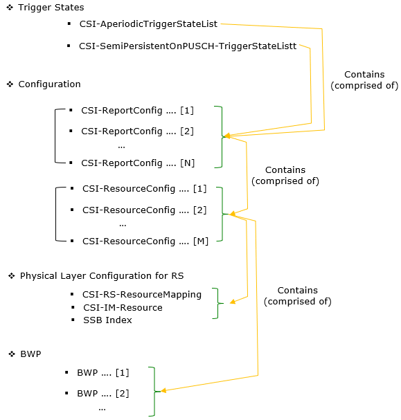
以下是另一幅描述了这些内容之间的关系的图。
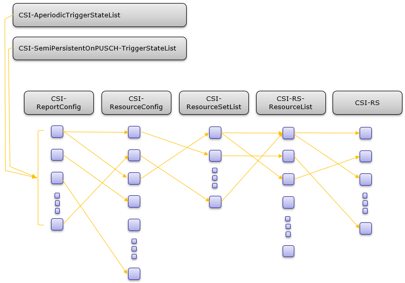
-
Note :为了方便检索,我把以上涉及内容的 ASN消息链接列在下边。
-
-
- CSI-ReportConfig
- CSI-ResourceConfig
- CSI-AperiodicTriggerStateList
- CSI-SemiPersistentOnPUSCH-TriggerStateList
- CSI-RS-ResourceMapping
- CSI-IM-Resource
-
CSI Report的RRC配置结构是NR中最复杂的结构之一,只通过学习这篇文章无法掌握这些内容,理解这些内容需要投入大量努力。我能做的是提供一些指引或提示帮你建立宏观的了解。
对于有一定兴趣但不需要深入了解的人来说:认识到这是一个特别复杂的结构和处理过程,并在你脑海中建立一个宏观的概念就可以了。
对于需要深入了解细节的人来说:你需要投入很多的努力。首先,需要对CSI框架的层次结构以及她们之间的关系有所了解,以下是根据我的理解做出的图示。如果你了解关系数据库,你将会对此类图形比较熟悉。或者如果你了解面向对象编程OOP画过类图,也可以帮助你理解此图。如果都没有的话就靠你的想象吧。按照图上提到的RRC消息结构,参考38.331去理解他的含义,大部分情况下38.331不会完全解释清楚,而是建议你去参考38.214或38.211。38.214中描述的内容不是那么容易理解,但你需要克服困难去掌握这些内容。
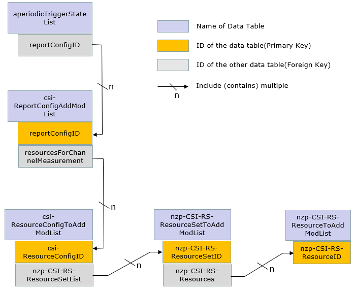
CSI report 使用什么参考信号?
CSI report可以使用SSB或者CSI-RS作为参考信号,,这两种信号都有各自的优缺点。
SSB : SSB的优点比较明显,SSB在初始接入阶段使用所以gNB总是在发送SSB信号(即使不是所有SSB burst都总在发送,但至少部分SSB burst应该时刻都在发送)。所以使用SSB进行CSI上报不会造成额外的开销。另一方面,使用SSB的缺点也很明显,首先由于SSB只能覆盖频域20RB,所以大部分情况下SSB只能覆盖部分信道带宽,而CSI-RS可以配置到任意频率范围。并且根据CSI上报的目的不同,需要配置不同的CSI测量间隔,而SSB不能灵活的配置时域上的间隔。
CSI-RS :CSI-RS的缺点是需要大量额外开销。然而使用CSI-RS的优点也很明显,它可以实现时域频域上的灵活配置,可以在任意频域范围、slot内任意OFDM符号内配置。
如何配置上报参数?(CSI-ReportConfig结构)
如何配置CSI上报参数?简单答案是“查看CSI-ReportConfig”,但是其中有太多的参数太过复杂。所以这一章节,我会试着基于38.214-5.2.1.1介绍此配置的整体结构。
CSI-ReportConfig总体结构可以总结如下。
-
reportConfigType :指示上报的调度方式,可以是周期、非周期或半静态。
-
- aperiodic
- semiPersistentOnPUCCH
- semiPersistentOnPUSCH
- periodic
-
reportQuantity : 指示测量内容,可以分为两大类。
-
- CSI-related quantities
- L1-RSRP-related quantities
-
reportFreqConfiguration : 指示频域上报粒度,可以是宽带或窄带。
-
timeRestrictionForChannelMeasurements : 指示是否对信道测量进行时域上限制。
-
timeRestrictionForInterferenceMeasurements : 指示是否对干扰测量进行时域上限制。
-
codebookConfig : 配置 type 1 和 type 2参数。
-
- Type I
- Type II
上报内容和依赖关系
每个上报内容的计算依赖于一个或多个其他参量,如下所示(38.214-5.2.1.4)。
| Reporting Parameters | Dependencies |
|---|---|
| LI | CQI,PMI,CRI,RI |
| CQI | PMI,RI,CRI |
| PMI | RI,CRI |
| RI | CRI |
让我根据 38.214-5.2.1.4.2对这些参数做更详细的描述。因为CSI Report配置可能是NR协议里最复杂或让人迷惑的部分,在实现协议或分析信令的过程中很可能会犯错。所以理解清楚每类Report quantity的RRC配置的基本要求和依赖哪些配置是非常有帮助的。
| ReportQuantity | Description |
|---|---|
| cri-RI-PMI-CQI cri-RI-LI-PMI-CQI | UE会上报宽带或窄带的最优预编码矩阵(预编码矩阵参考CSI Codebook内容)。需要干扰测量参考信号和码本配置。也就是需要配置 CSI-ReportConfig->csi-IM-ResourcesForInterference和CSI-ReportConfig->codebookConfig |
| cri-RI-i1 | 期望码本配置为codebookType =‘typeI-SinglePanel’ 并且pmi-FormatIndicator = wideband PMI。UE在整个CSI报告频带上只上报PMI的单个宽带指示,即PMI的i1。 |
| cri-RI-i1-CQI | 期望码本配置为codebookType ='typeI-SinglePanel’并且pmi-FormatIndicator = wideband PMI。UE在整个CSI报告频带上只上报PMI的单个宽带指示i1。CQI是在假设预编码器Np >≥ 1的情况下,基于上报的i1计算得到(这些预编码器对应相同的i1但不同的i2)针对每个PRG,UE假设从Np 个预编码器中随机选择一个预编码器计算CQI,其中PRG的尺寸由高层参数pdsch-BundleSizeForCSI给出。 |
| cri-RI-CQI | Case 1 : 配置了non-PMI-PortIndication UE应仅报告与 PortIndexFor8Ranks的配置字段相对应的 RI。 Case 2 : 没有配置non-PMI-PortIndication UE 假定CSI-RS 端口索引与ranks相关联. 此处的rank和层layer是{1,2,4,8}。当计算rank的CQI时,UE 应为所选的CSI-RS 资源使用为该rank指示的端口。指定端口的预编码器应假定为按比例缩放 1/sqrt(layer)的单位矩阵。不要求码本配置,需要干扰测量配置。意即需要配置CSI-ReportConfig->csi-IM-ResourcesForInterference |
| cri-RSRP ssb-index-RSRP | Case 1 : groupBasedBeamReporting = ‘disabled’ UE 不需要更新超过 64 个 CSI-RS 和/或 SSB 资源的测量值, 并且UE应在每个上报配置上报nrofReportedRS (高层配置) 个不同的CRI或SSBRI 。 Case 2 : groupBasedBeamReporting = ‘enabled’ UE 不需要更新超过 64 个 CSI-RS 和/或 SSB 资源的测量值,并且UE应在每个上报配置上报2个不同的CRI或SSBRI , 其中UE同时接收到的CSI-RS和/或SSB资源,要么是用单个空间域接收滤波器(也即波束方向相同),要么是用多个空间域接收滤波器(也即波束方向不同)。不要求配置干扰测量和码本配置,如果配置的是ssb-index-RSRP, 需要配置csi-SSB-ResourceSetToAddModList |
| cri-SINR ssb-index-SINR | Case 1 : groupBasedBeamReporting = ‘disabled’ UE 不需要更新超过 64 个 CSI-RS 和/或 SSB 资源的测量值, 并且UE应在每个上报配置上报nrofReportedRS (高层配置) 个不同的CRI或SSBRI 。 Case 2 : groupBasedBeamReporting = ‘enabled’ UE 不需要更新超过 64 个 CSI-RS 和/或 SSB 资源的测量值,并且UE应在每个上报配置上报2个不同的CRI或SSBRI , 其中UE同时接收到的CSI-RS和/或SSB资源,要么是用单个空间域接收滤波器(也即波束方向相同),要么是用多个空间域接收滤波器(也即波束方向不同)。不要求配置干扰测量和码本配置,如果配置的是ssb-index-SINR, 需要配置csi-SSB-ResourceSetToAddModList |
| Common to All | Case 1 : 周期上报 确保配置的PUCCH分配了足够的资源去承载上报内容。(例如, 配置使用PUCCH format 2 上报,确保足够的nrofsymbols, nrofPRBs 和 maxCodeRate ) Case 2 : 非周期上报 确保配置了 UCIonPUSCH 。 |
ReportConfig详细内容
以下是从各种来源收集的CSI-ReportConfig参数的详细内容。可以粗略分为两大类:窄带和宽带,详细内容在下一节介绍。
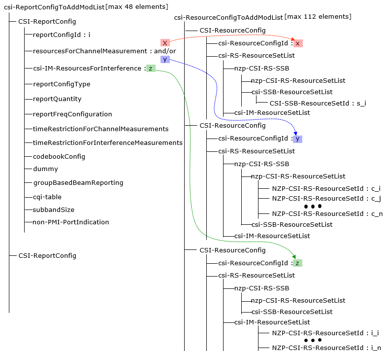
carrier : 指示使用哪个服务小区的CSI-ResourceConfig配置。如果该字段不存在,使用与上报配置相同服务小区的CSI-ResourceConfig配置。
resourcesForChannelMeasurement : 用于信道测量的资源配置。指示"carrier"配置的服务小区的CSI-ResourceConfig的csi-ResourceConfigId 。 这里指示的CSI-ResourceConfig只能是NZP-CSI-RS 和/或 SSB资源。CSI-ReportConfig和CSI-ResourceConfig指示的bwp-Id对应的DL BWP相关联。
csi-IM-ResourcesForInterference : 用于干扰测量的资源配置。指示本小区CSI-ResourceConfig的csi-ResourceConfigId。这是指示的CSI-ResourceConfig只能是CSI-IM资源。这里CSI-ResourceConfig携带的bwp-Id必须与resourcesForChannelMeasurement指示的相等。
nzp-CSI-RS-ResourcesForInterference : 用于干扰测量的NZP CSI RS资源。 指示"carrier"配置的服务小区的CSI-ResourceConfig的csi-ResourceConfigId。这是指示的CSI-ResourceConfig只能NZP-CSI-RS资源.。这里CSI-ResourceConfig携带的bwp-Id必须与resourcesForChannelMeasurement指示的相等。
groupBasedBeamReporting : 打开/关闭 基于组波束的上报。参考38.214-5.2.1.4.2,总结如下
-
enabled : 并且对于每个报告配置,UE应该在单个报告中上报nrofReportedRS个不同的CRI或SSBRI。
-
disabled : UE应该在单个报告中上报两个不同的CRI或SSBRI,其中UE同时接收到的CSI-RS和/或SSB资源,要么是用单个空间域接收滤波器(也即波束方向相同),要么是用多个空间域接收滤波器(也即波束方向不同)。
reportQuantity : 决定哪些上报量(如SSB RSRP、CQI、PMI、RI等) 应该被测量和上报 。
csi-ReportingBand :测量粒度为窄带时需要配置此参数。决定了窄带大小与哪些位置的窄带需要测量并上报。
CodebookConfig : 决定了码本矩阵的类型和哪些码本所以可以上报。
dumy : 预留字段,忽略。
non-PMI-PortIndication : 计算RI/CQI的端口指示。 为每一个信道测量使用的CSI-RS资源的每个rank指定一个端口,指示使用哪R个端口,只在没有PMI反馈的时候使用。
- non-PMI-PortIndication第一条对应 CSI-ResourceConfig -> ResourceSetListN -> ZP-CSI-RS-ResourceSet -> NZP-CSI-RS-Resources[0]。CSI-ResourceConfigId 与上述 CSIReportConfigId 一起在 CSI-MeasId 中表示;
- non-PMI-PortIndication第二条对应 CSI-ResourceConfig -> ResourceSetList -> NZP-CSI-RS-ResourceSet->NZP-CSI-RS-Resources[1];
- 以此类推。
nrofReportedRS : 每个report上报的测量资源个数( 配置为non-group-based上报情况下)。N <= N_max, N_max 由UE能力决定是2或4。 该字段不存在时UE认为值为1。
p0alpha : CSI上报传输功控参数p0-alpha集的索引。详见38.214-6.2.1.2 。
PortIndexFor8Ranks : 仅在CSI-ReportConfig.non-PMI-PortIndication配置存在时使用。指定了UE可以测量和上报的最大RI值。(详见38.214-5.2.1.4.2)。
timeRestrictionForChannelMeasurements : 决定上报使用哪个CSI-RS资源测量。参考38.214-5.2.2.1描述如下。
- Configured : UE 应仅根据与 CSI 资源设置相关联的 NZP CSI-RS 的最近一次(不迟于 CSI 参考资源)的时机来推导用于计算上行链路时隙 n 中报告的 CSI 的信道测量。
- NotConfigure : UE 应仅基于与 CSI 资源设置相关联的 NZP CSI-RS,不迟于 CSI 参考资源,导出用于计算上行链路时隙 n 中报告的 CSI 值的信道测量值。
timeRestrictionForInterferenceMeasurements :与上边的逻辑相同。参考38.214-5.2.2.1描述如下
- Configured : UE 应基于最近的不迟于 CSI 参考资源、CSI-IM 和/或 NZP CSI-RS 的时机来计算上行链路时隙 n 中报告的 CSI 值,以用于与 CSI 资源相关联的干扰测量。
- NotConfigure : UE 应仅基于用于干扰测量的 CSI-IM 和/或 NZP CSI-RS 得出用于计算上行链路时隙 n 中报告的 CSI 值的干扰测量,不迟于与 CSI 资源设置相关联的 CSI 参考资源。
cqi-FormatIndicator : 指示UE应上报单个(宽带)CQI或多个(窄带)CQI。
| Value | Description (based on 38.214 - 5.2.1.4) |
|---|---|
| Wideband | CSI上报带宽内每个码字上报一个宽带CQI |
| Subband | CSI上报带宽内每个子带报告每个码字的一个CQI |
pmi-FormatIndicator :指示UE应上报单个(宽带)CQI或多个(窄带)PMI。
| Value | Description (based on 38.214 - 5.2.1.4) |
|---|---|
| Wideband | CSI上报带宽内每个码字上报一个PMI |
| Subband | Case 1 : 天线端口数不为2 CSI带宽内上报单个宽带指示(i1)并且每个子带上报一个子带指示(i2)。Case 2 : 天线端口数为2 CSI上报带宽内每个子带上报一个PMI。 |
cqi-Table : 目前使用的三种不同类型的CQI表如下所示,表1表2的BLER标准是0.1,表3的标准是0.00001。
< 38.214 - Table 5.2.2.1-2: 4-bit CQI Table 1>
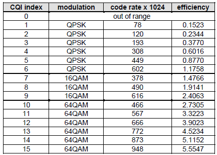
< 38.214 - Table 5.2.2.1-3: 4-bit CQI Table 2>
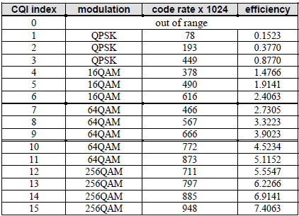
< 38.214 - Table 5.2.2.1-4: 4-bit CQI Table 3>
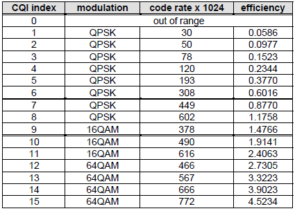
上报粒度 - 窄带 vs 宽带
基于以下问题,CSI报告大概有两种选择:上报值是代表整个频域?还是只代表特定某段频率?
上报值(测量值)代表整个频率带宽就叫做“宽带”报告。而值只代表一段特定带宽就叫“子带报告”。总结如下( 38.214 - 5.2.1.4)。
- Wideband : UE report one CQI/PMI report per Codeword for the whole band.
- Subband : UE report one CQI/PMI report per Codeword for each subband whole band.
宽带还是子带取决于多个RRC参数的组合,总结如下(参考38.214 - 5.2.1.4)
| reportQuantity | cqi-FormatIndicator | pmi-FormatIndicator | Frequency Granularity |
|---|---|---|---|
| cri-RI-PMI-CQI or cri-RI-LI-PMI-CQI | widebandCQI | widebandPMI | Wideband |
| cri-RI-i1 | Any | Any | Wideband |
| cri-RI-CQI or cri-RI-i1-CQI | widebandCQI | Any | Wideband |
| cri-RSRPorssb-Index-RSRP | Any | Any | Wideband |
| Else | Subband |
NOTE : 如果码本类型设置为 'typeII-r16’或 ‘typeII-PortSelection-r16’,UE不期望配置pmi-FormatIndicator。(38.214-5.2.1.4)
当UE进行子带粒度的上报时,需要知道测量子带的大小和位置,如何配置这些信息?一部分通过协议预定义,一部分通过RRC配置。
< 38.214-Table 5.2.1.4-2: Configurable subband sizes >

NOTE : 如果UE在小于24个PRB的BWP上配置了CSI报告,那么UE期望频域粒度配置为宽带(38.214-5.2.1.4)。
NOTE : 可以看到Subband size一列中有两个值,如果确定应该使用哪个值?由CSI-ReportConfig中配置的subbandsize决定。如果subbandsize = value1使用第一个值,如果subbandsize = value2使用第二个值。
每个bit代表的PRB个数由上表(38.214-Table 5.2.1.4-2)给出,基本上每bit代表的PRB个数根据BWP带宽不同而不同。
reportFreqConfiguration SEQUENCE {
cqi-FormatIndicator ENUMERATED { widebandCQI, subbandCQI } OPTIONAL,
pmi-FormatIndicator ENUMERATED { widebandPMI, subbandPMI } OPTIONAL,
csi-ReportingBand CHOICE {
subbands3 BIT STRING(SIZE(3)),
subbands4 BIT STRING(SIZE(4)),
subbands5 BIT STRING(SIZE(5)),
subbands6 BIT STRING(SIZE(6)),
subbands7 BIT STRING(SIZE(7)),
subbands8 BIT STRING(SIZE(8)),
subbands9 BIT STRING(SIZE(9)),
subbands10 BIT STRING(SIZE(10)),
subbands11 BIT STRING(SIZE(11)),
subbands12 BIT STRING(SIZE(12)),
subbands13 BIT STRING(SIZE(13)),
subbands14 BIT STRING(SIZE(14)),
subbands15 BIT STRING(SIZE(15)),
subbands16 BIT STRING(SIZE(16)),
subbands17 BIT STRING(SIZE(17)),
subbands18 BIT STRING(SIZE(18)),
…,
subbands19-v1530 BIT STRING(SIZE(19))
} OPTIONAL
上报配置触发方式与资源配置的映射
下表基于38.214 Table 5.2.1.4-1: Triggering/Activation of CSI Reporting for the possible CSI-RS Configurations
| Resource Configuration | Report Configuration | ||
|---|---|---|---|
| CSI-RS Configuration | Periodic CSI | Semi-Persistent CSI | Aperiodic CSI |
| Periodic CSI-RS | No dynamictriggering/activation | Reporting on PUCCH : Triggering by MAC CEReporting on PUSCH : Triggering by DCI | Triggered by DCI, additionally by MAC CE |
| Semi Periodic CSI-RS | Not Supported | Reporting on PUCCH : Triggering by MAC CEReporting on PUSCH : Triggering by DCI | Triggered by DCI, additionally by MAC CE |
| Aperiodic CSI-RS | Not Supported | Not Supported | Triggered by DCI, additionally by MAC CE |
如何解释上表? 根据关注点不同可以有以下几种解释方式。
当把Report Configuration作为自变量,Resource Configuration作为因变量的时候,上表可以解释如下
- 当Report configuration是周期的,Resource Configuration(CSI-RS Configuration = NZP CSI RS or CSI-IM)只能也是周期的。
- 当Report configuration是半静态的,Resource Configuration(CSI-RS Configuration = NZP CSI RS or CSI-IM)可以是周期或半静态的。
- 当Report configuration是非周期的,Resource Configuration(CSI-RS Configuration = NZP CSI RS or CSI-IM)可以是任意类型(周期、半静态、非周期)。
当把Resource Configuration作为自变量,Report Configuration作为因变量的时候,上表可以解释如下
- 当Resource Configuration(CSI-RS Configuration = NZP CSI RS or CSI-IM)是周期的,Report Configuration可以是任意类型 (周期、半静态、非周期)。
- 当Resource Configuration(CSI-RS Configuration = NZP CSI RS or CSI-IM)是半静态的,Report Configuration可以是非周期或半静态的。
- 当Resource Configuration(CSI-RS Configuration = NZP CSI RS or CSI-IM)是非周期的,Report Configuration只能是非周期的。
CSI流程图 :周期 vs 非周期
这些配置的工作原理如下。周期和非周期如下所示,而半静态可以视为周期和非周期的结合。半静态的第一个周期与非周期类似,一旦第一个周期被触发,CSI RS和CSI上报就按照周期上报。
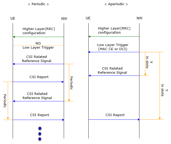
NOTE : X 和 Y 参考 38.802
- 非周期CSI-RS时域偏移X是指CSI-RS触发到非周期CSI-RS传输的时间间隔,单位为slot。
- 非周期CSI上报时域偏移Y是指非周期CSI上报触发和非周期CSI报告的时间间隔,单位为slot。
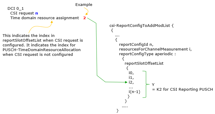
当配置reportSlotOffsetList时,需要确保其元素个数与PUSCH-Config->TimeDomainAllocationList中的元素个数相同,根据38.331所述如下。
reportSlotOffsetList
Timing offset Y for semi persistent reporting using PUSCH. This field lists the allowed offset values. This list must have the same number of entries as the pusch-TimeDomainAllocationList in PUSCH-Config. A particular value is indicated in DCI. The network indicates in the DCI field of the UL grant, which of the configured report slot offsets the UE shall apply. The DCI value 0 corresponds to the first report slot offset in this list, the DCI value 1 corresponds to the second report slot offset in this list, and so on. The first report is transmitted in slot n+Y, second report in n+Y+P, where P is the configured periodicity. Timing offset Y for aperiodic reporting using PUSCH. This field lists the allowed offset values. This list must have the same number of entries as the pusch-TimeDomainAllocationList in PUSCH-Config. A particular value is indicated in DCI. The network indicates in the DCI field of the UL grant, which of the configured report slot offsets the UE shall apply. The DCI value 0 corresponds to the first report slot offset in this list, the DCI value 1 corresponds to the second report slot offset in this list, and so on (see TS 38.214, clause 6.1.2.1).
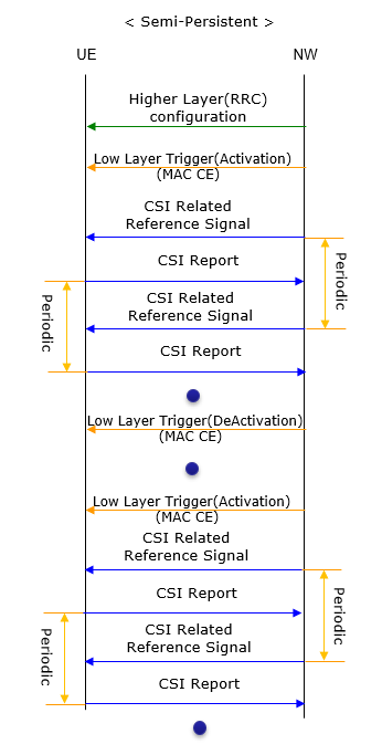
图示中表达的周期是由RRC参数配置的。根据物理信道与上报周期类型,周期参数配置如下表所示。
| Report Periodicity Type | Report Physical Channel | RRC Parameter to determin the periodicty |
|---|---|---|
| Periodic | PUCCH | reportSlotConfig |
| Semi-Persistent | PUCCH | reportSlotConfig |
| Semi-Persistent | PUSCH | reportSlotOffsetList |
NOTE : 当码本使能时,PUCCH上可以上报codebook type I,PUSCH上可以上报codebook type I 和 II(参考 38.214 - 5.2.3, 5.2.4)
NOTE : reportSlotOffsetList定义了一列reportslotOffsets,具体使用哪个的索引由 DCI 0_1 中"CSI Request" 字段决定。
UE计算耗时
当网络侧触发了CSI报告请求,UE无法立即计算测量结果并上报。UE需要一定时间去进行测量并计算测量结果。UE上报CSI需要耗时的多少在38.214 - 5.4中描述,下图为协议解读。
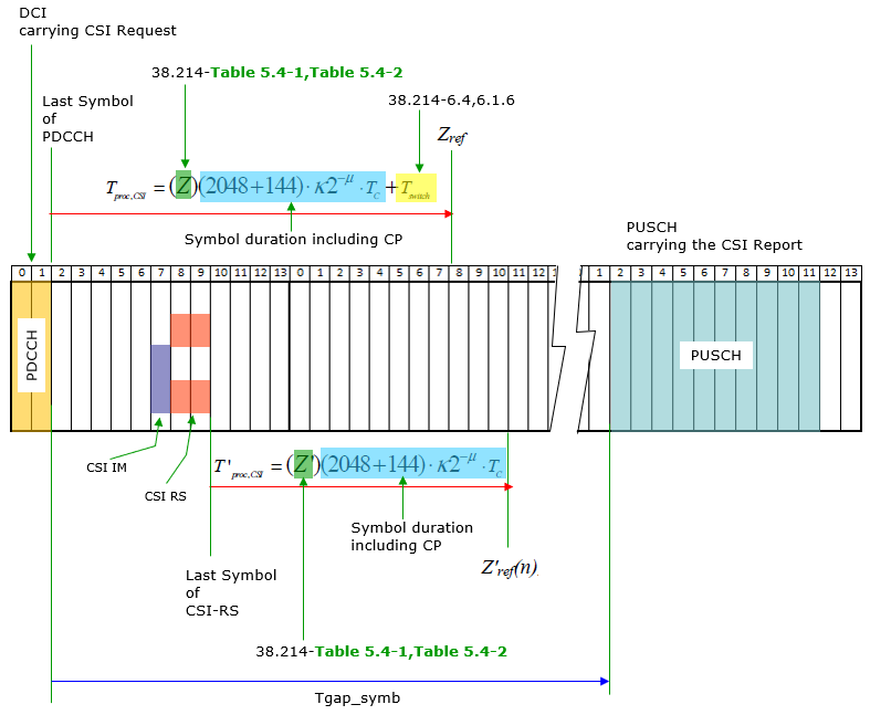
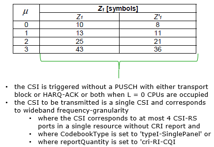
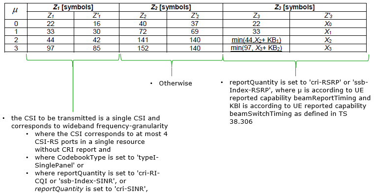
上图中的Z, Z’来自下面的表格。表格下的注释描述了什么场景下使用哪个表格的哪一行。
< 38.214-Table 5.4-1: CSI computation delay requirement 1 >
< 38.214-Table 5.4-2: CSI computation delay requirement 2 >
如何配置非周期报告触发器 ?
当非周期报告时,上报由DCI触发,某些情况下也会需要MAC CE + DCI触发。理论上听起来很简单,触发本身是简单的,但配置触发条件包含了多个组件间的相互作用,是比较复杂的。
以下是触发器配置和触发过程涉及到的组件。
DCI 0_1 -> CSI request :指定了配置在CSI-AeriodicTriggerStateList或MAC CE(Aperiodic CSI Trigger State Subselection MAC CE)码点中的Aperiodic Trigger State索引。字段长度由CSI-MeasConfig->reportTriggerSize定义。
DCI 0_1 CSI Request指示了什么? : 简单地说,如果字段长度足够指示所有备选项,就直接指示索引值。否则,指示的是MAC CE中codepoint的索引。
如果还是不清楚,参考38.214-5.2.1.5.1如下。希望能描述的更清楚 -????.
When the number of configured CSI triggering states in CSI-AperiodicTriggerStateList is greater than 2^(NTS) −1 , where N**TS is the number of bits in the DCI CSI request field, the UE receives a subselection indication, as described in subclause 38.321 6.1.3.13 (Aperiodic CSI Trigger State Subselection MAC CE) used to map up to 2NTS −1 trigger states to the codepoints of the CSI request field in DCI. N**TS is configured by the higher layer parameter reportTriggerSize where N**TS ∈{0,1, 2,3, 4,5,6}
以下是一个DCI 0_1触发非周期上报的例子,如你所见,每一个CSI request只能触发一个associatedReportConfigInfoList,但associatedReportConfigInfoList能关联一个或多个reportConfig,所以能够触发一个或多个上报。通常这部分RRC配置都很长所以你需要结合实际例子去了解。下面这个关系图应该能帮助你了解配置的总体结构。
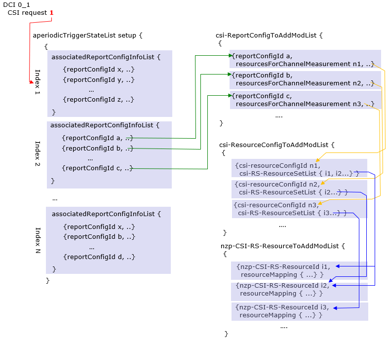
触发非周期的RRC配置 : 下面是以上描述提到的一些RRC参数。
CSI-MeasConfig ::= SEQUENCE {
...
reportTriggerSize
INTEGER (0..6) OPTIONAL,
aperiodicTriggerStateList
SetupRelease { CSI-AperiodicTriggerStateList },
...
}
CSI-AperiodicTriggerStateList ::= SEQUENCE (SIZE (1..maxNrOfCSI-AperiodicTriggers)) OF CSI-AperiodicTriggerState
CSI-AperiodicTriggerState ::= SEQUENCE {
associatedReportConfigInfoList
SEQUENCE (SIZE(1..maxNrofReportConfigPerAperiodicTrigger)) OF CSI-AssociatedReportConfigInfo,
...
}
CSI-AssociatedReportConfigInfo ::= SEQUENCE {
reportConfigId
CSI-ReportConfigId,
resourcesForChannel
CHOICE {
nzp-CSI-RS SEQUENCE {
resourceSet
INTEGER (1..maxNrofNZP-CSI-RS-ResourceSetsPerConfig),
qcl-info
SEQUENCE (SIZE(1..maxNrofAP-CSI-RS-ResourcesPerSet)) OF TCI-StateId OPTIONAL -- Cond Aperiodic
},
csi-SSB-ResourceSet
INTEGER (1..maxNrofCSI-SSB-ResourceSetsPerConfig)
},
csi-IM-ResourcesForInterference
INTEGER(1..maxNrofCSI-IM-ResourceSetsPerConfig),
nzp-CSI-RS-ResourcesForInterference
INTEGER (1..maxNrofNZP-CSI-RS-ResourceSetsPerConfig)
...
}
resourceSet :指示了资源集的索引(从1开始),资源集位于CSI-ReportConfig ( associated ReportConfig中resourcesForChannelMeasurement指示的) -> CSI-ResourceConfig -> Elements for resourcesForChannelMeasurement -> nzp-CSI-RS-ResourceSetList。
qcl-info : 为每个nzp-CSI-RS-ResourcesforChannel指示的NZP-CSI-RS-ResourceSet中包含的每个 NZP-CSI-RS-Resource提供QCL信息的TCI-States参考列表。每个TCI-StateId指的是TCI-State,该TCI-State具有tci-StateId的值,并且定义在PDSCH-Config中的tci-StatesToAddModList中,该PDSCH-Config包含在对应于resourcesForChannelMeasurement(在上面reportConfigId表示的CSI-ReportConfig中)所属的服务小区的DL BWP中 。
简言之,
- 是BWP-Downlink -> PDSCH-Config -> tci-StatesToAddModList的参考列表
- 此列表中的位置对应NZP-CSI-RS-ResourceSet中的位置。(qcl-info-forChannel中的第一项对应NZP-CSI-RS-ResourceSet中的第一个nzp-CSI-RS-Resources,,qcl-info-forChannel中的第二项对应第二个nzp-CSI-RS-Resources, 依次类推)
csi-SSB-ResourceSet : CSI-SSB-ResourceSet for channel measurements. Entry number in csi-SSB-ResourceSetList in the CSI-ResourceConfig indicated by resourcesForChannelMeasurement in the CSI-ReportConfig indicated by reportConfigId above (value 1 corresponds to the first entry, value 2 to the second entry, and so on).
简言之, 指示了资源集中的第几个,资源集是CSI-ResourceConfig (indicated by resourcesForChannelMeasurement of the associated ReportConfig) -> csi-SSB-ResourceSetList
csi-IM-ResourcesForInterference : CSI-IM-ResourceSet for interference measurement. Entry number in csi-IM-ResourceSetList in the CSI-ResourceConfig indicated by csi-IM-ResourcesForInterference in the CSI-ReportConfig indicated by reportConfigId above (value 1 corresponds to the first entry, value 2 to the second entry, and so on). The indicated CSI-IM-ResourceSet should have exactly the same number of resources like the NZP-CSI-RS-ResourceSet indicated in nzp-CSI-RS-ResourcesforChannel.
简言之, 指示了资源集中的第几个,资源集是CSI-ResourceConfig(indicated by csi-IM-ResourcesForInterference of the associated ReportConfig) ->CSI-IM-ResourceSetList
nzp-CSI-RS-ResourcesForInterference : NZP-CSI-RS-ResourceSet for interference measurement. Entry number in nzp-CSI-RS-ResourceSetList in the CSI-ResourceConfig indicated by nzp-CSI-RSResourcesForInterference in the CSI-ReportConfig indicated by reportConfigId above (value 1 corresponds to the first entry, value 2 to the second entry, and so on).
简言之, 指示了资源集中的第几个,资源集是CSI-ResourceConfig (indicated by nzp-CSI-RSResourcesForInterference of the associated ReportConfig) -> nzp-CSI-RS-ResourceSetList
CSI-AssociatedReportConfigInfo与上报和测量元素都有关系,下图帮助你理解总体结构。
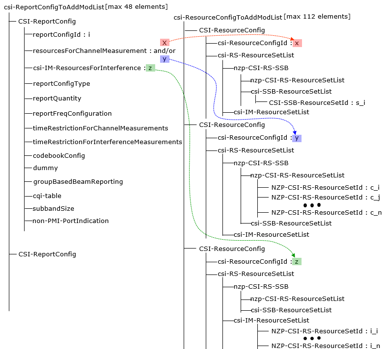
以下是CSI-ReportConfig的通常结构。CSI-ReportConfig由不同的资源集组成,绿色箭头指向特定的资源集ID。例如c_i指示了nzp-CSI-RS-ResourceSetToAddModList中定义的一个nzp-CSI-RS-ResourceSet。
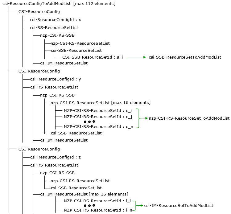
CSI上报RRC配置参数
PDSCH-Config ::=
SEQUENCE {
dataScramblingIdentityPDSCH
INTEGER (0..1007)
OPTIONAL,
dmrs-DownlinkForPDSCH-MappingTypeA
SetupRelease { DMRS-DownlinkConfig } OPTIONAL,
dmrs-DownlinkForPDSCH-MappingTypeB
SetupRelease { DMRS-DownlinkConfig }
OPTIONAL,
tci-StatesToAddModList
SEQUENCE (SIZE(1..maxNrofTCI-States)) OF TCI-State
OPTIONAL,
-- Need N
tci-StatesToReleaseList
SEQUENCE (SIZE(1..maxNrofTCI-States)) OF TCI-StateId OPTIONAL,
-- Need N
vrb-ToPRB-Interleaver
ENUMERATED {n2, n4},
resourceAllocation
ENUMERATED { resourceAllocationType0, resourceAllocationType1, dynamicSwitch},
pdsch-AllocationList
SEQUENCE (SIZE(1..maxNrofDL-Allocations)) OF PDSCH-TimeDomainResourceAllocation ,
pdsch-AggregationFactor
ENUMERATED { n2, n4, n8 } OPTIONAL,
rateMatchPatternToAddModList
SEQUENCE (SIZE (1..maxNrofRateMatchPatterns)) OF RateMatchPattern
OPTIONAL, -- Need N
rateMatchPatternToReleaseList
SEQUENCE (SIZE (1..maxNrofRateMatchPatterns)) OF RateMatchPatternId
OPTIONAL, -- Need N
rateMatchPatternGroup1
SEQUENCE (SIZE (1..maxNrofRateMatchPatterns)) OF RateMatchPatternId
OPTIONAL, -- Need R
rateMatchPatternGroup2
SEQUENCE (SIZE (1..maxNrofRateMatchPatterns)) OF RateMatchPatternId
OPTIONAL, -- Need R
rbg-Size
ENUMERATED {config1, config2},
mcs-Table
ENUMERATED {qam64, qam256},
maxNrofCodeWordsScheduledByDCI
ENUMERATED {n1, n2} OPTIONAL,
-- Need R
prb-BundlingType
CHOICE {
static
SEQUENCE {
bundleSize
ENUMERATED { n4, wideband } OPTIONAL
},
dynamic
SEQUENCE {
bundleSizeSet1
ENUMERATED { n4,wideband,n2-wideband,n4-wideband} OPTIONAL,
-- Need S
bundleSizeSet2
ENUMERATED { n4,wideband} OPTIONAL
-- Need S
}
},
zp-CSI-RS-ResourceToAddModList
SEQUENCE (SIZE (1..maxNrofZP-CSI-RS-Resources)) OF ZP-CSI-RS-Resource OPTIONAL,
-- Need N
zp-CSI-RS-ResourceToReleaseList
SEQUENCE (SIZE (1..maxNrofZP-CSI-RS-Resources)) OF ZP-CSI-RS-ResourceId OPTIONAL,
-- Need M
aperiodic-ZP-CSI-RS-ResourceSetsToAddModList
SEQUENCE (SIZE (1..maxNrofZP-CSI-RS-Sets)) OF ZP-CSI-RS-ResourceSet OPTIONAL, -- Need N
aperiodic-ZP-CSI-RS-ResourceSetsToReleaseList
SEQUENCE (SIZE (1..maxNrofZP-CSI-RS-Sets)) OF ZP-CSI-RS-ResourceSetId
OPTIONAL, -- Need N
sp-ZP-CSI-RS-ResourceSetsToAddModList
SEQUENCE (SIZE (1..maxNrofZP-CSI-RS-Sets)) OF ZP-CSI-RS-ResourceSet OPTIONAL, -- Need N
sp-ZP-CSI-RS-ResourceSetsToReleaseList SEQUENCE (SIZE (1..maxNrofZP-CSI-RS-Sets)) OF ZP-CSI-RS-ResourceSetId
OPTIONAL, -- Need N
...
}
CSI-MeasConfig ::= SEQUENCE {
nzp-CSI-RS-ResourceToAddModList
SEQUENCE (SIZE (1..maxNrofNZP-CSI-RS-Resources)) OF NZP-CSI-RS-Resource OPTIONAL,
nzp-CSI-RS-ResourceToReleaseList
SEQUENCE (SIZE (1..maxNrofNZP-CSI-RS-Resources)) OF NZP-CSI-RS-ResourceId OPTIONAL,
nzp-CSI-RS-ResourceSetToAddModList
SEQUENCE (SIZE (1..maxNrofNZP-CSI-RS-ResourceSets)) OF NZP-CSI-RS-ResourceSet OPTIONAL,
nzp-CSI-RS-ResourceSetToReleaseList
SEQUENCE (SIZE (1..maxNrofNZP-CSI-RS-ResourceSets)) OF NZP-CSI-RS-ResourceSetId OPTIONAL,
csi-IM-ResourceToAddModList
SEQUENCE (SIZE (1..maxNrofCSI-IM-Resources)) OF CSI-IM-Resource OPTIONAL,
csi-IM-ResourceToReleaseList
SEQUENCE (SIZE (1..maxNrofCSI-IM-Resources)) OF CSI-IM-ResourceId OPTIONAL,
csi-IM-ResourceSetToAddModList
SEQUENCE (SIZE (1..maxNrofCSI-IM-ResourceSets)) OF CSI-IM-ResourceSet OPTIONAL,
csi-IM-ResourceSetToReleaseList
SEQUENCE (SIZE (1..maxNrofCSI-IM-ResourceSets)) OF CSI-IM-ResourceSetId OPTIONAL,
csi-SSB-ResourceSetToAddModList
SEQUENCE (SIZE (1..maxNrofCSI-SSB-ResourceSets)) OF CSI-SSB-ResourceSet OPTIONAL,
csi-SSB-ResourceSetToAddReleaseList
SEQUENCE (SIZE (1..maxNrofCSI-SSB-ResourceSets)) OF CSI-SSB-ResourceSetId OPTIONAL,
csi-ResourceConfigToAddModList
SEQUENCE (SIZE (1..maxNrofCSI-ResourceConfigurations)) OF CSI-ResourceConfig OPTIONAL,
csi-ResourceConfigToReleaseList
SEQUENCE (SIZE (1..maxNrofCSI-ResourceConfigurations)) OF CSI-ResourceConfigId OPTIONAL,
csi-ReportConfigToAddModList
SEQUENCE (SIZE (1..maxNrofCSI-ReportConfigurations)) OF CSI-ReportConfig OPTIONAL,
csi-ReportConfigToReleaseList
SEQUENCE (SIZE (1..maxNrofCSI-ReportConfigurations)) OF CSI-ReportConfigId OPTIONAL,
reportTriggerSize
INTEGER (0..6) OPTIONAL,
aperiodicTriggerStateList
SetupRelease { CSI-AperiodicTriggerStateList },
semiPersistentOnPUSCH-TriggerStateList
SetupRelease { CSI-SemiPersistentOnPUSCH-TriggerStateList } OPTIONAL,
...
}
TCI-State ::= SEQUENCE {
tci-StateId
TCI-StateId,
qcl-Type1
QCL-Info,
qcl-Type2
QCL-Info OPTIONAL, -- Need R
...
}
QCL-Info ::=
SEQUENCE {
cell
ServCellIndex OPTIONAL, -- Need R
bwp-Id
BWP-Id OPTIONAL, -- Cond CSI-RS-Indicated
referenceSignal
CHOICE {
csi-rs
NZP-CSI-RS-ResourceId,
ssb
SSB-Index
},
qcl-Type
ENUMERATED {typeA, typeB, typeC, typeD},
...
}
ZP-CSI-RS-Resource ::= SEQUENCE {
zp-CSI-RS-ResourceId
ZP-CSI-RS-ResourceId,
resourceMapping
CSI-RS-ResourceMapping,
periodicityAndOffset
CSI-ResourcePeriodicityAndOffset OPTIONAL,
...
}
ZP-CSI-RS-ResourceSet ::= SEQUENCE {
zp-CSI-RS-ResourceSetId
ZP-CSI-RS-ResourceSetId,
zp-CSI-RS-ResourceIdList
SEQUENCE (SIZE(1..maxNrofZP-CSI-RS-ResourcesPerSet)) OF ZP-CSI-RS-ResourceId,
...
}
NZP-CSI-RS-Resource ::= SEQUENCE {
nzp-CSI-RS-ResourceId
NZP-CSI-RS-ResourceId,
resourceMapping
CSI-RS-ResourceMapping,
powerControlOffset
INTEGER (-8..15),
powerControlOffsetSS
ENUMERATED{db-3, db0, db3, db6} OPTIONAL, -- Need R
scramblingID
ScramblingId,
periodicityAndOffset
CSI-ResourcePeriodicityAndOffset OPTIONAL,-
qcl-InfoPeriodicCSI-RS
TCI-StateId OPTIONAL, -- Cond Periodic
...
}
NZP-CSI-RS-ResourceSet ::= SEQUENCE {
nzp-CSI-ResourceSetId
NZP-CSI-RS-ResourceSetId,
nzp-CSI-RS-Resources
SEQUENCE (SIZE (1..maxNrofNZP-CSI-RS-ResourcesPerSet)) OF NZP-CSI-RS-ResourceId,
repetition
ENUMERATED { on, off } OPTIONAL,
aperiodicTriggeringOffset INTEGER(0..4) OPTIONAL,
trs-Info
ENUMERATED {true} OPTIONAL,
...
}
CSI-RS-ResourceMapping ::= SEQUENCE {
frequencyDomainAllocation CHOICE {
row1
BIT STRING (SIZE (4)),
row2
BIT STRING (SIZE (12)),
row4
BIT STRING (SIZE (3)),
other
BIT STRING (SIZE (6))
},
nrofPorts
ENUMERATED {p1,p2,p4,p8,p12,p16,p24,p32},
firstOFDMSymbolInTimeDomain
INTEGER (0..13),
firstOFDMSymbolInTimeDomain2
INTEGER (2..12) OPTIONAL, -- Need R
cdm-Type
ENUMERATED {noCDM, fd-CDM2, cdm4-FD2-TD2, cdm8-FD2-TD4},
density CHOICE {
dot5
ENUMERATED {evenPRBs, oddPRBs},
one
NULL,
three
NULL,
spare
NULL
},
freqBand
CSI-FrequencyOccupation,
...
}
CSI-ResourcePeriodicityAndOffset ::= CHOICE {
slots4
INTEGER (0..3),
slots5
INTEGER (0..4),
slots8
INTEGER (0..7),
slots10
INTEGER (0..9),
slots16
INTEGER (0..15),
slots20
INTEGER (0..19),
slots32
INTEGER (0..31),
slots40
INTEGER (0..39),
slots64
INTEGER (0..63),
slots80
INTEGER (0..79),
slots160
INTEGER (0..159),
slots320
INTEGER (0..319),
slots640
INTEGER (0..639)
}
CSI-FrequencyOccupation ::= SEQUENCE {
startingRB
INTEGER (0..maxNrofPhysicalResourceBlocks-1),
nrofRBs
INTEGER (24..maxNrofPhysicalResourceBlocksPlus1),
...
}
CSI-IM-Resource ::= SEQUENCE {
csi-IM-ResourceId
CSI-IM-ResourceId,
csi-IM-ResourceElementPattern
CHOICE {
pattern0 SEQUENCE {
subcarrierLocation-p0
ENUMERATED { s0, s2, s4, s6, s8, s10 },
symbolLocation-p0
INTEGER (0..12)
},
pattern1 SEQUENCE {
subcarrierLocation-p1
ENUMERATED { s0, s4, s8 },
symbolLocation-p1
INTEGER (0..13)
}
} OPTIONAL, -- Need M
freqBand
CSI-FrequencyOccupation OPTIONAL,
periodicityAndOffset
CSI-ResourcePeriodicityAndOffset OPTIONAL,
PeriodicOrSemiPersistent
...
}
CSI-IM-ResourceSet ::= SEQUENCE {
csi-IM-ResourceSetId
CSI-IM-ResourceSetId,
csi-IM-Resources
SEQUENCE (SIZE(1..maxNrofCSI-IM-ResourcesPerSet)) OF CSI-IM-ResourceId,
...
}
CSI-SSB-ResourceSet ::= SEQUENCE {
csi-SSB-ResourceSetId
CSI-SSB-ResourceSetId,
csi-SSB-ResourceList
SEQUENCE (SIZE(1..maxNrofCSI-SSB-ResourcePerSet)) OF SSB-Index,
...
}
CSI-ResourceConfig ::= SEQUENCE {
csi-ResourceConfigId
CSI-ResourceConfigId,
csi-RS-ResourceSetList
CHOICE {
nzp-CSI-RS-SSB
SEQUENCE {
nzp-CSI-RS-ResourceSetList
SEQUENCE (SIZE (1..maxNrofNZP-CSI-RS-ResourceSetsPerConfig)) OF NZP-CSI-RS-ResourceSetId OPTIONAL,
csi-SSB-ResourceSetList
SEQUENCE (SIZE (1..maxNrofCSI-SSB-ResourceSetsPerConfig)) OF CSI-SSB-ResourceSetId OPTIONAL
},
csi-IM-ResourceSetList
SEQUENCE (SIZE (1..maxNrofCSI-IM-ResourceSetsPerConfig)) OF CSI-IM-ResourceSetId
},
bwp-Id
BWP-Id,
resourceType
ENUMERATED { aperiodic, semiPersistent, periodic },
...
}
CSI-ReportConfig ::= SEQUENCE {
reportConfigId
CSI-ReportConfigId,
carrier
ServCellIndex OPTIONAL,
resourcesForChannelMeasurement
CSI-ResourceConfigId,
csi-IM-ResourcesForInterference
CSI-ResourceConfigId OPTIONAL,
nzp-CSI-RS-ResourcesForInterference
CSI-ResourceConfigId OPTIONAL,
reportConfigType
CHOICE {
periodic SEQUENCE {
reportSlotConfig
CSI-ReportPeriodicityAndOffset,
pucch-CSI-ResourceList
SEQUENCE (SIZE (1..maxNrofBWPs)) OF PUCCH-CSI-Resource
},
semiPersistentOnPUCCH SEQUENCE {
reportSlotConfig
CSI-ReportPeriodicityAndOffset,
pucch-CSI-ResourceList
SEQUENCE (SIZE (1..maxNrofBWPs)) OF PUCCH-CSI-Resource
},
semiPersistentOnPUSCH SEQUENCE {
reportSlotConfig
ENUMERATED {sl5, sl10, sl20, sl40, sl80, sl160, sl320},
reportSlotOffsetList
SEQUENCE (SIZE (1.. maxNrofUL-Allocations)) OF INTEGER(0..32),
p0alpha
P0-PUSCH-AlphaSetId
},
aperiodic SEQUENCE {
reportSlotOffsetList
SEQUENCE (SIZE (1..maxNrofUL-Allocations)) OF INTEGER(0..32)
}
},
reportQuantity CHOICE {
none NULL,
cri-RI-PMI-CQI
NULL,
cri-RI-i1
NULL,
cri-RI-i1-CQI
SEQUENCE {
pdsch-BundleSizeForCSI
ENUMERATED {n2, n4} OPTIONAL
},
cri-RI-CQI
NULL,
cri-RSRP
NULL,
ssb-Index-RSRP
NULL,
cri-RI-LI-PMI-CQI
NULL
},
reportFreqConfiguration SEQUENCE {
cqi-FormatIndicator
ENUMERATED { widebandCQI, subbandCQI } OPTIONAL,
pmi-FormatIndicator
ENUMERATED { widebandPMI, subbandPMI } OPTIONAL,
csi-ReportingBand CHOICE {
subbands3
BIT STRING(SIZE(3)),
subbands4
BIT STRING(SIZE(4)),
subbands5
BIT STRING(SIZE(5)),
subbands6
BIT STRING(SIZE(6)),
subbands7
BIT STRING(SIZE(7)),
subbands8
BIT STRING(SIZE(8)),
subbands9
BIT STRING(SIZE(9)),
subbands10
BIT STRING(SIZE(10)),
subbands11
BIT STRING(SIZE(11)),
subbands12
BIT STRING(SIZE(12)),
subbands13
BIT STRING(SIZE(13)),
subbands14
BIT STRING(SIZE(14)),
subbands15
BIT STRING(SIZE(15)),
subbands16
BIT STRING(SIZE(16)),
subbands17
BIT STRING(SIZE(17)),
subbands18
BIT STRING(SIZE(18)),
...,
subbands19-v1530
BIT STRING(SIZE(19))
} OPTIONAL
} OPTIONAL,
timeRestrictionForChannelMeasurements
ENUMERATED {configured, notConfigured},
timeRestrictionForInterferenceMeasurements
ENUMERATED {configured, notConfigured},
codebookConfig
CodebookConfig OPTIONAL,
nrofCQIsPerReport
ENUMERATED {n1, n2} OPTIONAL,
groupBasedBeamReporting
CHOICE {
enabled
NULL,
disabled
SEQUENCE {
nrofReportedRS
ENUMERATED {n1, n2, n3, n4} OPTIONAL
}
},
cqi-Table
ENUMERATED {table1, table2, table3, spare1} OPTIONAL,
subbandSize
ENUMERATED {value1, value2},
non-PMI-PortIndication
SEQUENCE (SIZE (1..maxNrofNZP-CSI-RS-ResourcesPerConfig)) OF PortIndexFor8Ranks OPTIONAL,
...,
[[
semiPersistentOnPUSCH-v1530 SEQUENCE {
reportSlotConfig-v1530
ENUMERATED {sl4, sl8, sl16}
} OPTIONAL
]]
}
CSI-ReportPeriodicityAndOffset ::= CHOICE {
slots4
INTEGER(0..3),
slots5
INTEGER(0..4),
slots8
INTEGER(0..7),
slots10
INTEGER(0..9),
slots16
INTEGER(0..15),
slots20
INTEGER(0..19),
slots40
INTEGER(0..39),
slots80
INTEGER(0..79),
slots160
INTEGER(0..159),
slots320
INTEGER(0..319)
}
PUCCH-CSI-Resource ::= SEQUENCE {
uplinkBandwidthPartId
BWP-Id,
pucch-Resource
PUCCH-ResourceId
}
PortIndexFor8Ranks ::= CHOICE {
portIndex8
SEQUENCE{
rank1-8
PortIndex8 OPTIONAL, -- Need R
rank2-8
SEQUENCE(SIZE(2)) OF PortIndex8 OPTIONAL, -- Need R
rank3-8
SEQUENCE(SIZE(3)) OF PortIndex8 OPTIONAL, -- Need R
rank4-8
SEQUENCE(SIZE(4)) OF PortIndex8 OPTIONAL, -- Need R
rank5-8
SEQUENCE(SIZE(5)) OF PortIndex8 OPTIONAL, -- Need R
rank6-8
SEQUENCE(SIZE(6)) OF PortIndex8 OPTIONAL, -- Need R
rank7-8
SEQUENCE(SIZE(7)) OF PortIndex8 OPTIONAL, -- Need R
rank8-8
SEQUENCE(SIZE(8)) OF PortIndex8 OPTIONAL -- Need R
},
portIndex4
SEQUENCE{
rank1-4
PortIndex4 OPTIONAL, -- Need R
rank2-4
SEQUENCE(SIZE(2)) OF PortIndex4 OPTIONAL, -- Need R
rank3-4
SEQUENCE(SIZE(3)) OF PortIndex4 OPTIONAL, -- Need R
rank4-4
SEQUENCE(SIZE(4)) OF PortIndex4 OPTIONAL -- Need R
},
portIndex2
SEQUENCE{
rank1-2
PortIndex2 OPTIONAL, -- Need R
rank2-2
SEQUENCE(SIZE(2)) OF PortIndex2 OPTIONAL -- Need R
},
portIndex1
NULL
}
CodebookConfig ::= SEQUENCE {
codebookType CHOICE {
type1 SEQUENCE {
subType CHOICE {
typeI-SinglePanel SEQUENCE {
nrOfAntennaPorts CHOICE {
two SEQUENCE {
twoTX-CodebookSubsetRestriction BIT STRING (SIZE (6))
},
moreThanTwo SEQUENCE {
n1-n2 CHOICE {
two-one-TypeI-SinglePanel-Restriction
BIT STRING (SIZE (8)),
two-two-TypeI-SinglePanel-Restriction
BIT STRING (SIZE (64)),
four-one-TypeI-SinglePanel-Restriction
BIT STRING (SIZE (16)),
three-two-TypeI-SinglePanel-Restriction
BIT STRING (SIZE (96)),
six-one-TypeI-SinglePanel-Restriction
BIT STRING (SIZE (24)),
four-two-TypeI-SinglePanel-Restriction
BIT STRING (SIZE (128)),
eight-one-TypeI-SinglePanel-Restriction
BIT STRING (SIZE (32)),
four-three-TypeI-SinglePanel-Restriction
BIT STRING (SIZE (192)),
six-two-TypeI-SinglePanel-Restriction
BIT STRING (SIZE (192)),
twelve-one-TypeI-SinglePanel-Restriction
BIT STRING (SIZE (48)),
four-four-TypeI-SinglePanel-Restriction
BIT STRING (SIZE (256)),
eight-two-TypeI-SinglePanel-Restriction
BIT STRING (SIZE (256)),
sixteen-one-TypeI-SinglePanel-Restriction
BIT STRING (SIZE (64))
},
typeI-SinglePanel-codebookSubsetRestriction-i2
BIT STRING (SIZE (16))
}
},
typeI-SinglePanel-ri-Restriction BIT STRING (SIZE (8))
},
typeI-MultiPanel SEQUENCE {
ng-n1-n2 CHOICE {
two-two-one-TypeI-MultiPanel-Restriction
BIT STRING (SIZE (8)),
two-four-one-TypeI-MultiPanel-Restriction
BIT STRING (SIZE (16)),
four-two-one-TypeI-MultiPanel-Restriction
BIT STRING (SIZE (8)),
two-two-two-TypeI-MultiPanel-Restriction
BIT STRING (SIZE (64)),
two-eight-one-TypeI-MultiPanel-Restriction
BIT STRING (SIZE (32)),
four-four-one-TypeI-MultiPanel-Restriction
BIT STRING (SIZE (16)),
two-four-two-TypeI-MultiPanel-Restriction
BIT STRING (SIZE (128)),
four-two-two-TypeI-MultiPanel-Restriction
BIT STRING (SIZE (64))
},
ri-Restriction BIT STRING (SIZE (4))
}
},
codebookMode INTEGER (1..2)
},
type2 SEQUENCE {
subType CHOICE {
typeII SEQUENCE {
n1-n2-codebookSubsetRestriction CHOICE {
two-one
BIT STRING (SIZE (16)),
two-two
BIT STRING (SIZE (43)),
four-one
BIT STRING (SIZE (32)),
three-two
BIT STRING (SIZE (59)),
six-one
BIT STRING (SIZE (48)),
four-two
BIT STRING (SIZE (75)),
eight-one
BIT STRING (SIZE (64)),
four-three
BIT STRING (SIZE (107)),
six-two
BIT STRING (SIZE (107)),
twelve-one
BIT STRING (SIZE (96)),
four-four
BIT STRING (SIZE (139)),
eight-two
BIT STRING (SIZE (139)),
sixteen-one
BIT STRING (SIZE (128))
},
typeII-RI-Restriction
BIT STRING (SIZE (2))
},
typeII-PortSelection SEQUENCE {
portSelectionSamplingSize
ENUMERATED {n1, n2, n3, n4} OPTIONAL,
typeII-PortSelectionRI-Restriction
BIT STRING (SIZE (2))
}
},
phaseAlphabetSize
ENUMERATED {n4, n8},
subbandAmplitude
BOOLEAN,
numberOfBeams
ENUMERATED {two, three, four}
}
}
}
CSI-AperiodicTriggerStateList ::= SEQUENCE (SIZE (1..maxNrOfCSI-AperiodicTriggers)) OF CSI-AperiodicTriggerState
CSI-AperiodicTriggerState ::= SEQUENCE {
associatedReportConfigInfoList
SEQUENCE (SIZE(1..maxNrofReportConfigPerAperiodicTrigger)) OF CSI-AssociatedReportConfigInfo,
...
}
CSI-AssociatedReportConfigInfo ::= SEQUENCE {
reportConfigId
CSI-ReportConfigId,
resourcesForChannel
CHOICE {
nzp-CSI-RS SEQUENCE {
resourceSet
INTEGER (1..maxNrofNZP-CSI-RS-ResourceSetsPerConfig),
qcl-info
SEQUENCE (SIZE(1..maxNrofAP-CSI-RS-ResourcesPerSet)) OF TCI-StateId OPTIONAL -- Cond Aperiodic
},
csi-SSB-ResourceSet
INTEGER (1..maxNrofCSI-SSB-ResourceSetsPerConfig)
},
csi-IM-ResourcesForInterference
INTEGER(1..maxNrofCSI-IM-ResourceSetsPerConfig),
nzp-CSI-RS-ResourcesForInterference
INTEGER (1..maxNrofNZP-CSI-RS-ResourceSetsPerConfig)
...
}
CSI-SemiPersistentOnPUSCH-TriggerStateList ::= SEQUENCE(SIZE (1..maxNrOfSemiPersistentPUSCH-Triggers)) OF CSI-SemiPersistentOnPUSCH-TriggerState
CSI-SemiPersistentOnPUSCH-TriggerState ::= SEQUENCE {
associatedReportConfigInfo
CSI-ReportConfigId,
...
}
MeasurementReport ::= SEQUENCE {
criticalExtensions
CHOICE {
measurementReport
MeasurementReport-IEs,
criticalExtensionsFuture
SEQUENCE {}
}
}
MeasurementReport-IEs ::= SEQUENCE {
measResults
MeasResults,
lateNonCriticalExtension
OCTET STRING OPTIONAL,
nonCriticalExtension
SEQUENCE{} OPTIONAL
}
MeasResults ::= SEQUENCE {
measId
MeasId,
measResultServingMOList
MeasResultServMOList,
measResultNeighCells
CHOICE {
measResultListNR
MeasResultListNR,
...,
measResultListEUTRA
MeasResultListEUTRA
} OPTIONAL,
...
}
MeasResultServMOList ::= SEQUENCE (SIZE (1..maxNrofServingCells)) OF MeasResultServMO
MeasResultServMO ::= SEQUENCE {
servCellId
ServCellIndex,
measResultServingCell
MeasResultNR,
measResultBestNeighCell
MeasResultNR OPTIONAL,
...
}
MeasResultListNR ::= SEQUENCE (SIZE (1..maxCellReport)) OF MeasResultNR
MeasResultNR ::= SEQUENCE {
physCellId
PhysCellId OPTIONAL,
measResult SEQUENCE {
cellResults SEQUENCE{
resultsSSB-Cell
MeasQuantityResults OPTIONAL,
resultsCSI-RS-Cell
MeasQuantityResults OPTIONAL
},
rsIndexResults SEQUENCE{
resultsSSB-Indexes
ResultsPerSSB-IndexList OPTIONAL,
resultsCSI-RS-Indexes
ResultsPerCSI-RS-IndexList OPTIONAL
} OPTIONAL
},
...,
[[
cgi-Info
CGI-Info OPTIONAL
]]
}
MeasResultListEUTRA ::= SEQUENCE (SIZE (1..maxCellReport)) OF MeasResultEUTRA
MeasResultEUTRA ::= SEQUENCE {
physCellId
PhysCellId,
measResult
MeasQuantityResultsEUTRA,
cgi-Info SEQUENCE {
cgi-info-EPC SEQUENCE {
cgi-info-EPC-legacy
CellAccessRelatedInfo-EUTRA-EPC,
cgi-info-EPC-list
SEQUENCE (SIZE (1..maxPLMN)) OF CellAccessRelatedInfo-EUTRA-EPC OPTIONAL
} OPTIONAL,
cgi-info-5GC
SEQUENCE (SIZE (1..maxPLMN)) OF CellAccessRelatedInfo-EUTRA-5GC OPTIONAL,
freqBandIndicator
FreqBandIndicatorEUTRA,
multiBandInfoList
MultiBandInfoListEUTRA OPTIONAL,
freqBandIndicatorPriority
ENUMERATED {true} OPTIONAL
} OPTIONAL,
...
}
CellAccessRelatedInfo-EUTRA-EPC ::= SEQUENCE {
plmn-IdentityList-eutra-epc
PLMN-IdentityList-EUTRA-EPC,
trackingAreaCode-eutra-epc
BIT STRING (SIZE (16)),
cellIdentity-eutra-epc
BIT STRING (SIZE (28))
}
PLMN-IdentityList-EUTRA-EPC::= SEQUENCE (SIZE (1..maxPLMN)) OF PLMN-Identity
PLMN-Identity ::= SEQUENCE {
mcc
MCC OPTIONAL, -- Cond MCC
mnc
MNC
}
CellAccessRelatedInfo-EUTRA-5GC ::= SEQUENCE {
plmn-IdentityList-eutra-5gc
PLMN-IdentityList-EUTRA-5GC,
trackingAreaCode-eutra-5gc
TrackingAreaCode,
ranac-5gc
RAN-AreaCode OPTIONAL,
cellIdentity-eutra-5gc
CellIdentity-EUTRA-5GC
}
PLMN-IdentityList-EUTRA-5GC::= SEQUENCE (SIZE (1..maxPLMN)) OF PLMN-Identity-EUTRA-5GC
PLMN-Identity-EUTRA-5GC ::= CHOICE {
plmn-Identity-EUTRA-5GC
PLMN-Identity,
plmn-index
INTEGER (1..maxPLMN)
}
CellIdentity-EUTRA-5GC ::= CHOICE {
cellIdentity-EUTRA
BIT STRING (SIZE (28)),
cellId-index
INTEGER (1..maxPLMN)
}
MultiBandInfoListEUTRA ::= SEQUENCE (SIZE (1..maxMultiBands)) OF FreqBandIndicatorEUTRA
MeasQuantityResults ::= SEQUENCE {
rsrp
RSRP-Range OPTIONAL,
rsrq
RSRQ-Range OPTIONAL,
sinr
SINR-Range OPTIONAL
}
MeasQuantityResultsEUTRA ::= SEQUENCE {
rsrp
RSRP-RangeEUTRA OPTIONAL,
rsrq
RSRQ-RangeEUTRA OPTIONAL,
sinr
SINR-RangeEUTRA OPTIONAL
}
ResultsPerSSB-IndexList::= SEQUENCE (SIZE (1..maxNrofIndexesToReport2)) OF ResultsPerSSB-Index
ResultsPerSSB-Index ::= SEQUENCE {
ssb-Index
SSB-Index,
ssb-Results
MeasQuantityResults OPTIONAL
}
ResultsPerCSI-RS-IndexList::= SEQUENCE (SIZE (1..maxNrofIndexesToReport2)) OF ResultsPerCSI-RS-Index
ResultsPerCSI-RS-Index ::= SEQUENCE {
csi-RS-Index
CSI-RS-Index,
csi-RS-Results
MeasQuantityResults OPTIONAL
}
maxNrofIndexesToReport
INTEGER ::= 32
maxNrofIndexesToReport2
INTEGER ::= 64
maxMultiBands
INTEGER ::= 8
maxCellReport
INTEGER ::= 8
maxNrofServingCells
INTEGER ::= 32
RRC配置实例
就个人而言,我认为想出适用于每个 UE 的 CSI 测量 / BeamManagement 的任何 RRC 配置示例并不容易。 即使您了解与 CSI 报告相关的每个组件的每个细节(即 38.211、38.214、38.331),整合所有这些单独的组件也太复杂(在许多情况下在 3GPP 规范文档中不清楚/令人困惑) 使整个报告过程按预期工作。 即使使用完全相同的配置,您也可能会遇到它可以与某些 UE 一起工作,但不能与其他 UE 一起工作,并且找不到导致不同结果的明确技术原因。
在这种情况下,我认为尝试使用协议一致性测试中使用的配置是个好主意。 即使与您在实际网络中看到的相比,它看起来有点过于简单,您可能希望一致性配置适用于大多数商业化 UE。
基本模板
以下是 38.508-1,v16.7 的 CSI 报告配置的基本模板。 从这些基本模板中,根据测试目的衍生出许多变化。
< 38.508-1 Table 4.6.3-38: CSI-MeasConfig >
| CSI-MeasConfig::= SEQUENCE { | |||
|---|---|---|---|
| nzp-CSI-RS-ResourceToAddModList SEQUENCE { | 1 entry | ||
| NZP-CSI-RS-Resource[1] | NZP-CSI-RS-Resource | entry 1 | |
| } | |||
| nzp-CSI-RS-ResourceToReleaseList | Not present | ||
| nzp-CSI-RS-ResourceSetToAddModList SEQUENCE { | 1 entry | ||
| NZP-CSI-RS-ResourceSet[1] | NZP-CSI-RS-ResourceSet | entry 1 | |
| } | |||
| nzp-CSI-RS-ResourceSetToReleaseList | Not present | ||
| csi-IM-ResourceToAddModList SEQUENCE { | 1 entry | ||
| CSI-IM-Resource[1] | CSI-IM-Resource | entry 1 | |
| } | |||
| csi-IM-ResourceToReleaseList | Not present | ||
| csi-IM-ResourceSetToAddModList SEQUENCE { | 1 entry | ||
| CSI-IM-ResourceSet[1] | CSI-IM-ResourceSet | ||
| } | |||
| csi-IM-ResourceSetToReleaseList | Not present | ||
| csi-SSB-ResourceSetToAddModList SEQUENCE { | 1 entry | ||
| CSI-SSB-ResourceSet[1] | CSI-SSB-ResourceSet | entry 1 | |
| } | |||
| csi-SSB-ResourceSetToAddReleaseList | Not present | ||
| csi-ResourceConfigToAddModList SEQUENCE { | 1 entry | ||
| CSI-ResourceConfig[1] | CSI-ResourceConfig | entry 1 | |
| } | |||
| csi-ResourceConfigToReleaseList | Not present | ||
| csi-ReportConfigToAddModList | 1 entry | ||
| CSI-ReportConfig[1] | CSI-ReportConfig | entry 1 | |
| } | |||
| csi-ReportConfigToReleaseList | Not present | ||
| reportTriggerSize | 0 | ||
| aperiodicTriggerStateList SetupRelease { | |||
| setup | CSI-AperiodicTriggerStateList | ||
| } | |||
| semiPersistentOnPUSCH-TriggerStateList | Not present | ||
| } |
< 38.508-1 Table 4.6.3-41: CSI-ResourceConfig >
| CSI-ResourceConfig ::= SEQUENCE { | |||
|---|---|---|---|
| csi-ResourceConfigId | CSI-ResourceConfigId | ||
| csi-RS-ResourceSetList CHOICE { | |||
| nzp-CSI-RS-SSB SEQUENCE { | |||
| nzp-CSI-RS-ResourceSetList SEQUENCE (SIZE (1…maxNrofNZP-CSI-RS-ResourceSetsPerConfig)) OF { | 2 entries | ||
| NZP-CSI-RS-ResourceSetId[0] | 0 | entry 1 | |
| NZP-CSI-RS-ResourceSetId[1] | 1 | entry 2 | |
| } | |||
| csi-SSB-ResourceSetList | Not present | ||
| } | |||
| } | |||
| bwp-Id | BWP-Id | ||
| resourceType | periodic | ||
| } |
< 38.508-1 Table 4.6.3-32: CSI-AperiodicTriggerStateList >
| Information Element | Value/Remark | Comment | FR1 | FR2 |
|---|---|---|---|---|
| CSI-AperiodicTriggerStateList ::= SEQUENCE (SIZE (1…maxNrOfCSI-AperiodicTriggers)) OF CSI-AperiodicTriggerState{ | 1 entry | |||
| CSI-AperiodicTriggerState[1] SEQUENCE { | entry 1 | |||
| associatedReportConfigInfoList SEQUENCE(SIZE(1…maxNrofReportConfigPerAperiodicTrigger))OF CSI-AssociatedReportConfigInfo { | 1 entry | |||
| CSI-AssociatedReportConfigInfo[1] SEQUENCE { | entry 1 | |||
| reportConfigId[1] | CSI-ReportConfigId | |||
| resourcesForChannel[1] CHOICE { | ||||
| nzp-CSI-RS SEQUENCE { | ||||
| resourceSet | 8 | 16 | ||
| qcl-info SEQUENCE (SIZE(1…maxNrofAP-CSI-RS-ResourcesPerSet)) OF { | 1 entry | |||
| TCI-StateId[1] | TCI-StateId | entry 1 | ||
| } | ||||
| } | ||||
| } | ||||
| csi-IM-ResourcesforInteference[1] | 8 | 16 | ||
| nzp-CSI-RS-ResourcesforInterference[1] | 8 | 16 | ||
| } | ||||
| } |
< 38.508-1 Table 4.6.3-85: NZP-CSI-RS-Resource >
| NZP-CSI-RS-Resource ::= SEQUENCE { | |||
|---|---|---|---|
| nzp-CSI-RS-ResourceId | NZP-CSI-RS-ResourceId | ||
| resourceMapping | CSI-RS-ResourceMapping | ||
| powerControlOffset | -3 | ||
| powerControlOffsetSS | Not present | ||
| scramblingID | ScramblingId | ||
| periodicityAndOffset | CSI-ResourcePeriodicityAndOffset | ||
| qcl-InfoPeriodicCSI-RS | TCI-StateId | ||
| } |
< 38.508-1 Table 4.6.3-43: CSI-ResourcePeriodicityAndOffset >
| CSI-ResourcePeriodicityAndOffset ::= CHOICE { | |||
|---|---|---|---|
| slots80 | 10 | FR1 | |
| slots320 | 40 | FR2 | |
| } |
< 38.508-1 Table 4.6.3-87: NZP-CSI-RS-ResourceSet>
| FR1 | FR2 | ||
|---|---|---|---|
| NZP-CSI-RS-ResourceSet ::= SEQUENCE { | |||
| nzp-CSI-ResourceSetId | NZP-CSI-RS-ResourceSetId | ||
| nzp-CSI-RS-Resources SEQUENCE (SIZE (1…maxNrofNZP-CSI-RS-ResourcesPerSet)) OF { | [1 entry] | ||
| NZP-CSI-RS-ResourceId[1] | NZP-CSI-RS-ResourceId | ||
| } | |||
| repetition | off | ||
| aperiodicTriggeringOffset | Not present | ||
| trs-Info | true | true | |
| } |
< 38.508-1 Table 4.6.3-34: CSI-IM-Resource >
| CSI-IM-Resource ::= SEQUENCE { | FR1 | FR2 | |
|---|---|---|---|
| csi-IM-ResourceId | CSI-IM-ResourceId | ||
| csi-IM-ResourceElementPattern CHOICE { | |||
| pattern1 SEQUENCE { | |||
| subcarrierLocation-p1 | s4 | ||
| symbolLocation-p1 | 3 | 4 | |
| } | |||
| } | |||
| freqBand | CSI-FrequencyOccupation | ||
| periodicityAndOffset | Not present | ||
| } |
< 38.508-1 Table 4.6.3-36: CSI-IM-ResourceSet >
| CSI-IM-ResourceSet ::= SEQUENCE { | |||
|---|---|---|---|
| csi-IM-ResourceSetId | CSI-IM-ResourceSetId | ||
| csi-IM-Resources SEQUENCE (SIZE(1…maxNrofCSI-IM-ResourcesPerSet)) { | 1 entry | ||
| CSI-IM-ResourceId[1] | CSI-IM-ResourceId | entry 1 | |
| } | |||
| } |
< 38.508-1 Table 4.6.3-39: CSI-ReportConfig >
| CSI-ReportConfig ::= SEQUENCE { | |||
|---|---|---|---|
| reportConfigId | CSI-ReportConfigId | ||
| carrier | ServCellIndex | ||
| resourcesForChannelMeasurement | CSI-ResourceConfigId | ||
| csi-IM-ResourcesForInterference | CSI-ResourceConfigId | ||
| nzp-CSI-RS-ResourcesForInterference | CSI-ResourceConfigId | ||
| reportConfigType CHOICE { | |||
| reportSlotOffsetList SEQUENCE (SIZE(1…maxNrofUL-Allocations)) OF INTEGER { | 1 entry | ||
| INTEGER[1] | 14 | entry 1 | |
| } | |||
| } | |||
| reportQuantity CHOICE { | |||
| cri-RI-PMI-CQI | NULL, | FR1 | |
| cri-RI-LI-PMI-CQI | NULL | FR2 | |
| } | |||
| reportFreqConfiguration SEQUENCE { | |||
| cqi-FormatIndicator | widebandCQI | ||
| pmi-FormatIndicator | widebandPMI | ||
| csi-ReportingBand | Not present | ||
| } | |||
| timeRestrictionForChannelMeasurements | notConfigured | ||
| timeRestrictionForInterferenceMeasurements | notConfigured | ||
| codebookConfig | CodebookConfig | ||
| dummy | Not present | ||
| groupBasedBeamReporting CHOICE { | |||
| disabled SEQUENCE { | |||
| nrofReportedRS | n1 | ||
| } | |||
| } | |||
| cqi-Table | table2 | FR1 | |
| table1 | FR2 | ||
| subbandSize | value2 | ||
| non-PMI-PortIndication | Not present | ||
| } |
< 38.508-1 Table 4.6.3-190: TCI-State >
| TCI-State ::= SEQUENCE { | |||
|---|---|---|---|
| tci-StateId | TCI-StateId | ||
| qcl-Type1 SEQUENCE { | |||
| cell | Not present | ||
| bwp-Id | Not present | ||
| referenceSignal CHOICE { | |||
| ssb | SSB-Index | ||
| } | |||
| qcl-Type | typeD | ||
| } | |||
| qcl-Type2 | Not present | ||
| } |
CSI RS for Tracking
Refer to following tables in 38.501-1.
- Table 5.4.1-5: CSI-RS-ResourceMapping for TRS
- Table 5.4.1-6: CSI-ResourcePeriodicityAndOffset for TRS
- Table 5.4.1-7: CSI-MeasConfig for TRS
- Table 5.4.1-8: NZP-CSI-RS-Resource for TRS
- Table 5.4.1-9: NZP-CSI-RS-ResourceSet for TRS
- Table 5.4.1-10: CSI-ResourceConfig for TRS
< 38.508-1 Table 5.4.1-5: CSI-RS-ResourceMapping for TRS >
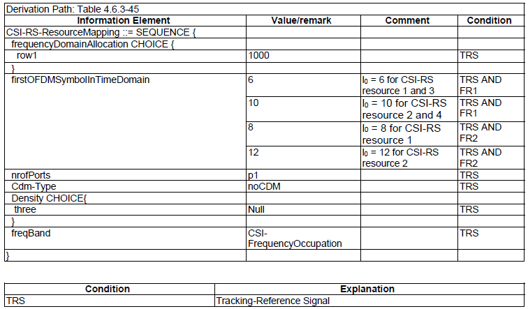
< 38.508-1 Table 5.4.1-6: CSI-ResourcePeriodicityAndOffset for TRS >
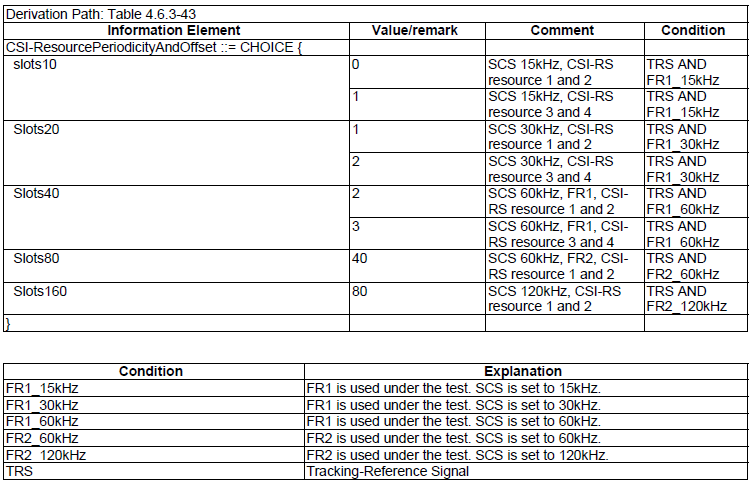
< 38.508-1 Table 5.4.1-7: CSI-MeasConfig for TRS >
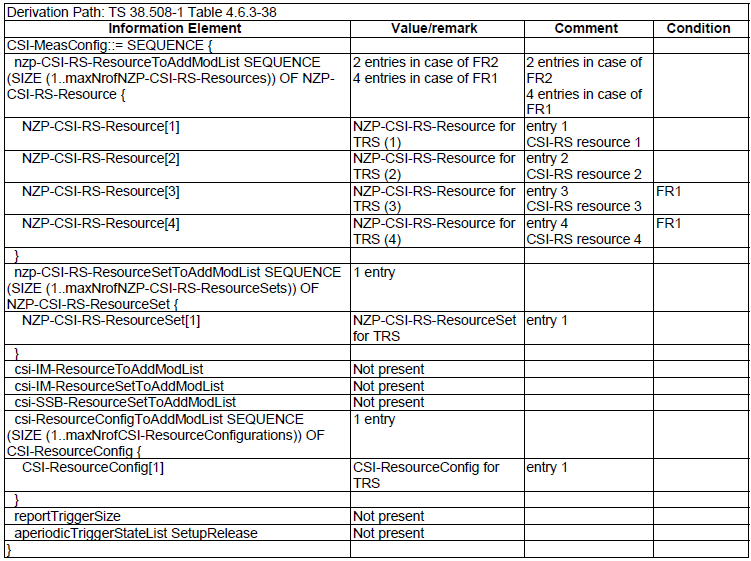
< 38.508-1 Table 5.4.1-8: NZP-CSI-RS-Resource for TRS >
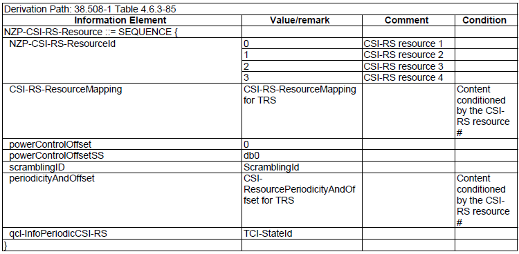
< 38.508-1 Table 5.4.1-9: NZP-CSI-RS-ResourceSet for TRS >
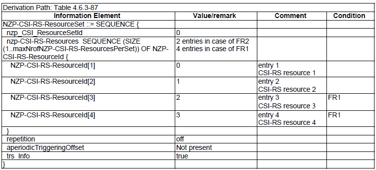
< 38.508-1 Table 5.4.1-10: CSI-ResourceConfig for TRS >
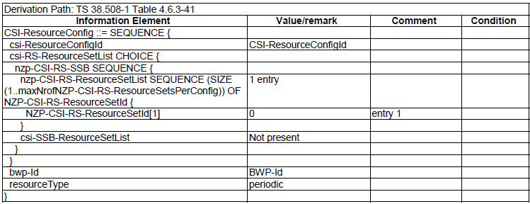
NZP-CSI-RS for Tracking
- Table 5.4.2.0-8: NZP-CSI-RS-Resource for TRS
- Table 5.4.2.0-9: CSI-RS-ResourceMapping for TRS
- Table 5.4.2.0-10: CSI-ResourcePeriodicityAndOffset for TRS
- Table 5.4.2.0-11: CSI-FrequencyOccupation for TRS
- Table 5.4.2.0-12: NZP-CSI-RS-ResourceSet for TRS
- Table 5.4.2.0-13: CSI-ResourceConfig for TRS
NZP CSI-RS for CSI Acquisition
- Table 5.4.2.0-14: NZP-CSI-RS-Resource
- Table 5.4.2.0-15: CSI-RS-ResourceMapping
- Table 5.4.2.0-16: CSI-ResourcePeriodicityAndOffset
- Table 5.4.2.0-17: CSI-FrequencyOccupation for CSI Acquisition
- Table 5.4.2.0-18: NZP-CSI-RS-ResourceSet for CSI Acquisition
- Table 5.4.2.0-19: CSI-ResourceConfig for CSI Acquisition
ZP CSI-RS for CSI Acquisition
- Table 5.4.2.0-20: ZP-CSI-RS-Resource
- Table 5.4.2.0-21: ZP CSI-RS-ResourceMapping
- Table 5.4.2.0-22: ZP CSI-ResourcePeriodicityAndOffset
- Table 5.4.2.0-23: ZP CSI-FrequencyOccupation
PDSCH-Config [TCI States]
- Table 5.4.2.0-26: PDSCH-Config
CSI-RS for beam refinement
- Table 5.4.2.0-29: NZP-CSI-RS-Resource
- Table 5.4.2.0-30: CSI-RS-ResourceMapping
- Table 5.4.2.0-31: CSI-ResourcePeriodicityAndOffset
- Table 5.4.2.0-32: CSI-FrequencyOccupation for beam refinement
- Table 5.4.2.0-33: NZP-CSI-RS-ResourceSet for beam refinement
- Table 5.4.2.0-34: CSI-ResourceConfig for beam refinement
CSI-RS for beam management
- Table 5.4.2.0-35: NZP-CSI-RS-Resource for beam management
- Table 5.4.2.0-36: CSI-RS-ResourceMapping for beam management
- Table 5.4.2.0-37: CSI-ResourcePeriodicityAndOffset for beam management
- Table 5.4.2.0-38: CSI-FrequencyOccupation for beam management
- Table 5.4.2.0-39: NZP-CSI-RS-ResourceSet for beam management
- Table 5.4.2.0-40: CSI-ResourceConfig for beam management
CSI Codebook
本页介绍CSI RS的波束赋形,可能是NR协议中最复杂的一部分。如果你对LTE波束赋形(TM9)有所了解,对理解本页内容会有帮助。简言之,这部分内容是关于38.214-5.2.2.2预编码矩阵(PMI),但通过反复阅读这一章节,我意识到不学习额外的文档是无法完全理解此部分内容的。我不确定要花费多久才能使你在理解上达到一定程度,但马上开始吧。本页面会长期缓慢更新,只要我得到更深的理解我就会更新一些。
什么是CSI码本?
什么是码本?不同情况下会有不同含义,但在CSI-RS这里提到的码本是指一组预编码矩阵。换一种说法,码本是一种将数据bit转换为映射到天线的数据的矩阵。
两种类型的码本: Type I和Type II
5G种定义了两种类型的码本。
- Type I 基于与 LTE 码本( LTE codebook)相同的逻辑。 NR Type I 码本稍微复杂一些,支持更多不同类型的矩阵。 基本上,这种类型使用了一组由 UE 报告和 RRC 配置选择的预定义矩阵。 (Ref [33])
- NR Type II 不是基于预定义的表格,它基于一个专门设计的带有很多参数的数学公式。 公式中的那些参数是由 RRC 和 UE 报告决定的。 如果您查看 Type II 码本,您不会看到像 Type I 码本这样的许多不同的表格。 您只会在 Type II 码本中看到一个表格,但您会注意到定义预编码矩阵的公式要复杂得多。 凭借那些复杂的公式和大量的参数,Type II 可以应用比 Type I 更复杂的预编码矩阵。 (Ref [33])
- Type II 基于更详细的 CSI 报告,主要针对 MU-MIMO 设计 (Multi User MIMO)
- Type I 和 Type II 码本均由基于二维 DFT 的波束网格构成,支持波束选择的 CSI 反馈以及两个极化之间基于 PSK 的同相组合. (Ref [34])
- 与 Type I 相比(Type I 报告仅定义所选波束的相位,而不是幅度),基于Type II 码本的 CSI 反馈报告所选波束的宽带和子带幅度信息. (Ref [34])
- The difference between Type I and Type II is well illustrated by Ref [38] as shown below. The point is that Type I select only one specific beam from a group of beams, whereas type II select a group of beam and linearly combine all the beams within the group.
- Type I和Type II之间的区别如下图所示Ref [38]。 关键是Type I从一组波束中只选择一个特定的波束,而Type II选择一组波束并线性组合组内的所有波束。

接收方是否必须知道预编码矩阵才能解码接收到的信号?
我们(接收者)应该知道预编码矩阵来解码接收到的信号吗? 答案因数据传输方案的设计方式而异。 大致有两种实现情况,如下所示。 简而言之,接收方不需要知道情况1中的预编码矩阵信息,而接收方应该知道情况2中的预编码矩阵。 (See Chapter 11 of [Ref 10])
< Case 1 >
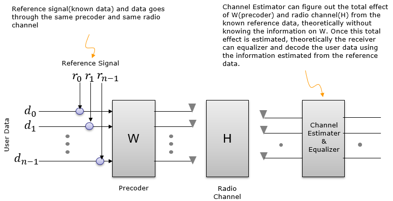
< Case 2 >
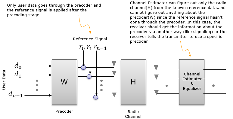
NR 实现属于 < Case 1 >.
大部分 LTE 传输模式(例如 TM1,2,3,4 等)属于 < Case 2 >。 即,仅对数据(例如,PDSCH)进行预编码,而不对用于信道估计的参考信号(即,小区特定参考信号)进行预编码。 在这种情况下,UE 应该知道 eNB 应用了哪个预编码矩阵。 UE 根据预定义的规范(如在 TM1、2、3 中)或 eNB 传递的信令信息(即 DCI 中的 PMI 索引字段)知道这一点。
但即使在LTE中,TM9也属于PDSCH携带自己的解调参考信号的<Case 1>。 在这种情况下,在 LTE 预编码步骤中不应用预编码矩阵。 相反,PDSCH 数据和 PDSCH DMRS 都将经历波束成形过程。 这种波束形成过程可以看作是一种预编码。 由于 PDSCH 数据和 PDSCH DMRS 都经过相同的波束成形过程,UE 不需要知道 eNB 使用的预编码矩阵。
那么为什么我们关心 NR 中的预编码器(码本)。 “我们不需要知道”并不意味着“它没用”。 即使它不是强制性的,但如果接收者知道码本,它肯定会对接收者有所帮助。
进一步研究参考信号
将解释进一步扩展到具有不同类型参考信号的各种可能情况,我将它们分类为以下情况。 这里写的评论是我画这张图时的想法,如果你深入细节,这些评论可能不是很清楚甚至误导,但通过这种方式至少它帮助我理解了整体数学流程和参考信号设计。
< Case 1 >
在这种情况下,有一个称为 CRS 的参考信号。 根据这个图,CRS被[H]矩阵(Channel Matrix)修改。 如果我们假设接受方预先知道CRS(例如,通过规范),接收方可以使用此信号通过比较接收到的 CRS 和预期的 CRS(规范中指定的 CRS)来估计 [H]。 那么问题是“接收者能否仅在知道 [H] 的情况下解码用户数据(d)?”。 很可能不能,因为用户数据不仅被 [H] 修改,还被 [W] 修改。 然后下一个问题是“接收者可以估计(计算出)[W] 吗?“ 接收者不能直接从接收到的信号中知道 [W]。 关于[W]的信息应该通过诸如信令消息或物理控制信息或预定义规范等其他方式为接收者所知。
LTE使用小区特定参考信号属于这种情况。
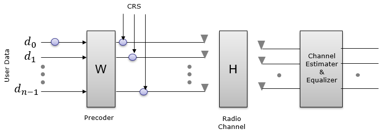
< Case 2 >
在这种情况下,有一个称为 DMRS 的参考信号。 根据该图,DMRS由[W](预编码矩阵)和[H]矩阵(通道矩阵)修改。 如果我们假设接收方事先已知 DMRS(例如,通过规范),则接收方可能能够通过使用 DMRS 校正接收到的信号来解码用户数据。 但是如果你问”UE 可以估计 [W] 和 [H] 吗?“。 很可能没有。接收者可以通过比较接收到的 DMRS 和预期的 DMRS 来估计 [H][W] 的乘积,但不可能分别估计 [H] 和 [W]。
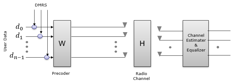
< Case 3 >
在这种情况下,有两个参考信号,称为 DMRS 和 CSI-RS。 根据该图,DMRS被[W](预编码矩阵)和[H]矩阵(信道矩阵)修改并且CSI-RS被[H]修改。 接收者可以估计 [H] 矩阵,但 W 矩阵可能不能直接从 DMRS 估计,因为 DMRS 被 [W] 和 [H] 修改,因此 [W] 信息将通过信令或预定义规范提供给接收者。 (理论上,如果接收器同时使用从 CSI-RS 和 DMRS 估计的 [H],它可以估计 [W])。 理论上,在这种情况下,接收者将能够仅使用 DMRS 解码用户数据。 如果 CSI-RS 将是有用的附加信息,但它不是关键的。
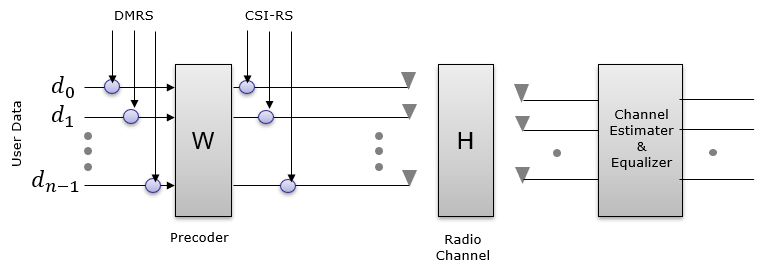
NOTE : 这与 NR FR1 的情况类似,其中不使用 BeamForming 并且 PDSCH/DMRS 基于来自 UE 的 CSI 报告进行预编码。
< Case 4 >
在这种情况下,DMRS 和 CSI-RS 都经过相同的过程。 它们都由 [X](Beam Forming)和 [H] 矩阵(通道矩阵)修改。 这是 PDSCH / DMRS 未预编码的情况。
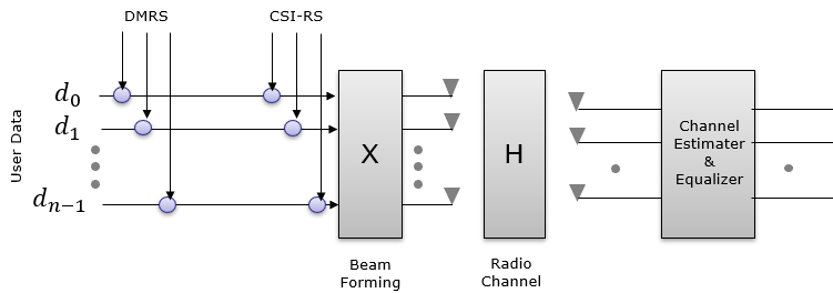
NOTE : 这与使用 BeamForming 但未预编码 PDSCH/DMRS 的 FR2 情况类似。 网络会从 UE 获得 CSI 报告,并可以根据报告调整矩阵 [X],但它不会为 PDSCH 应用任何预编码矩阵。
< Case 5 >
在这种情况下,有两个参考信号,称为 DMRS 和 CSI-RS。 根据该图,DMRS由[W](预编码矩阵)、[X](波束成形)和[H]矩阵(信道矩阵)修改,CSI-RS由[X]和[H]修改。 接收者可以估计 [H] [X] 矩阵,但 [X] 和 [H] 不能单独估计。 从 DMRS,接收者可以估计 [H] [X] [W],但它们不能单独分开。 总之,在这种情况下,不能单独估计任何矩阵,但理论上接收者应该能够仅使用 DMRS 解码用户数据,因为 DMRS 可以撤消所有组合矩阵 [H] [X] [W] 的影响 .
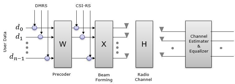
NOTE : 这与使用 BeamForming 并且预编码 PDSCH/DMRS 的 FR2 的情况类似。 网络将从 UE 获得 CSI 报告,并可以根据报告调整矩阵 [X],并根据 UE 报告为 PDSCH 应用预编码矩阵。
UE或gNB如何知道预编码信息?
从 UE 的角度来看,一种典型的方式是将 PMI 的测量报告发送给 gNB,并且可能假设 gNB 将使用它报告的 PMI(预编码矩阵指示符)…但要记住的重要一点是…让 gNB 使用 UE 报告的 PMI不是强制性的 。它可能会也可能不会使用相同的 PMI,这取决于它自己的情况。 即使gNB使用与UE报告的PMI不同的PMI,UE也可以解码下行数据,因为下行数据(PDSCH)从一开始就携带自己的参考信号,如上一节<案例2>中所述。 UE 可以使用 DMRS 估计信道,并且在许多情况下,这种类型的信道估计足以对 PDSCH 进行解码。
从gNB的角度来看,一个典型的方式是告诉UE发送 SRS并根据SRS的信道估计选择一个特定的PMI,并通过 DCI 0_1(TMPI字段)告诉UE使用一个特定的PMI。 在这种情况下,UE 应使用 gNB 指定的特定预编码矩阵。 如果我们可以假设 UE 和 gNB 处于保证信道互易性的条件下(例如经过良好校准的 TDD 信道),则 gNB 可以使用来自 SRS 的信道信息来估计下行信道质量和选择下行波束。
从哪开始?了解基本术语
当我开始阅读第 38.214-5.2.2.2 节时,我遇到的第一个问题是找出奇怪的单个字符参数的含义,例如 N1、N2、O1、O2,这些参数在 TS(技术规范)中没有明确定义,以及其他一些术语,如“面板”(如 RRC 消息中所示的单面板、多面板)。当某些术语在 TS 文档中没有明确定义时,很可能在某些 TDocs (R1-XXXXX) 中对其进行了描述,并在没有明确解释的情况下转移到 TS 文档中。所以我开始搜索关于这个主题的 TDocs,我发现了一个 TDoc Ref [1],[5],[6],[7],[8] ,它似乎是这个主题的起源,以及[Ref 2] and [Ref 3]中的一些其他文档,这将有助于我们理解其他术语,如“Panel”。
NOTE : 基本上,NR CSI 码本设计的大部分基本概念都继承自 LTE Rel 13 FD-MIMO 码本设计。 您会在 LTE TDocs 中找到很多详细的描述和图表。查看链接[Ref 14] , [Ref15] 并查看CSI Codebook文档。
N1,N2,O1,O2 : 这些单字母参数的定义在 R1-1612661 中进行了说明,如下所示。 N1,N2由水平和垂直方向的天线数量决定。 O1、O2 表示 DFT 过采样。
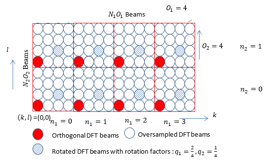
NOTE : O1、O2 的总体功能是在波束管理(波束跟踪)期间确定波束的扫描步数。 O1 确定水平方向的扫描步长,O2 确定垂直方向的扫描步长。 简而言之,O1、O2 越高,可以以更小的步长(即更精细的角度)扫描光束。
我从下面显示的三星白皮书中找到了一个更清晰的插图,它可以将每个波束矩阵与垂直和水平波束的角度相关联。
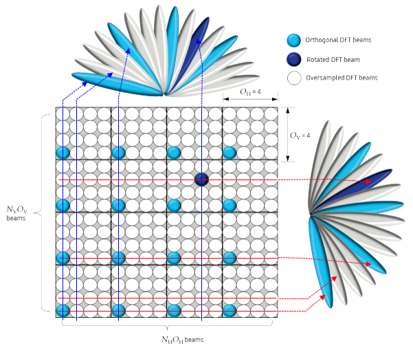
Source : Massive MIMO for New Radio (SamSung White Paper)
我们如何在现实中实现这些波束? 物理实现会有所不同。 一个实现的例子可以说明如下。
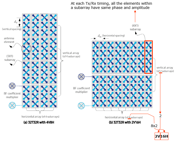
Source : Massive MIMO for New Radio (SamSung White Paper)
N1、N2、O1、O2 在 3GPP 中定义如下。 我在表格中添加了一些额外的列,因为这些额外的列经常在其他部分中使用。
<Type 1 Single Panel : Based on 38.214 v15.3-Table 5.2.2.2.1-2: Supported configurations of (N1,N2) and (O1,O2)>
| Number of CSI-RS antenna ports | (N1,N2) | 2*N1*N2=# of CSI ports | (O1,O2) | N1*O1 | N2*O2 | N1*O1*N2*O2=Ac(Bitmap in SinglePanel n1-n2) |
|---|---|---|---|---|---|---|
| 4 | (2,1) | 2*2*1 = 4 | (4,1) | 2*4=8 | 1*1=1 | 2*4*1*1 = 8 |
| 8 | (2,2) | 2*2*2 = 8 | (4,4) | 2*4=8 | 2*4=8 | 2*4*2*4 = 64 |
| (4,1) | 2*4*1 = 8 | (4,1) | 4*4=16 1*1=1 | 4*4*1*1 = 16 | ||
| 12 | (3,2) | 2*3*2 = 12 | (4,4) | 3*4=12 | 2*4=8 | 3*4*2*4 = 96 |
| (6,1) | 2*6*1 = 12 | (4,1) | 6*4=24 | 1*1=1 | 6*4*1*1 = 24 | |
| 16 | (4,2) | 2*4*2 = 16 | (4,4) | 4*4=16 | 2*4=8 | 4*4*2*4 = 128 |
| (8,1) | 2*8*1 = 16 | (4,1) | 8*4=32 | 1*1=1 | 8*4*1*1 = 32 | |
| 24 | (4,3) | 2*4*3 = 24 | (4,4) | 4*4=16 | 3*4=12 | 4*4*3*4 = 192 |
| (6,2) | 2*6*2 = 24 | (4,4) | 6*4=24 | 2*4=8 | 6*4*2*4 = 192 | |
| (12,1) | 2*12*1 = 24 | (4,1) | 12*4=48 | 1*1=1 | 12*4*1*1 = 48 | |
| 32 | (4,4) | 2*4*4 = 32 | (4,4) | 4*4=16 | 4*4=16 | 4*4*4*4 = 256 |
| (8,2) | 2*8*2 = 32 | (4,4) | 8*4=32 | 2*4=8 | 8*4*2*4 = 256 | |
| (16,1) | 2*16*1 = 32 | (4,1) | 16*4=64 | 1*1=1 | 16*4*1*1 = 64 |
NOTE : 请注意,O1 始终是 4,而 O2 只有两种可能性:1 或 4。
<Type 1 Multi Panel : Based on 38.214 v15.3-Table 5.2.2.2.2-1: Supported configurations of (Ng,N1,N2) and (O1,O2)>
| Number of CSI-RS antenna ports | (Ng,N1,N2) | 2*Ng*N1*N2=# of CSI ports | (O1,O2) | N1*O1 | N2*O2 | N1*O1*N2*O2=Ac(Bitmap in MultiPanel ng-n1-n2) |
|---|---|---|---|---|---|---|
| 8 | (2,2,1) | 2*2*2*1 = 8 | (4,1) | 2*4=8 | 1*1=1 | 2*4*1*1 = 8 |
| 16 | (2,4,1) | 2*2*4*1 = 16 | (4,1) | 4*4=16 | 1*1=1 | 4*4*1*1 = 16 |
| (4,2.1) | 2*4*2*1 = 16 | (4,1) | 2*4=8 | 1*1=1 | 1*4*1*1 = 8 | |
| (2,2,2) | 2*2*2*2 = 16 | (4,4) | 2*4=8 | 2*4=8 | 2*4*2*4 = 64 | |
| 32 | (2,8,1) | 2*2*8*1 = 32 | (4,1) | 8*4=32 | 1*1=1 | 8*4*1*1 = 32 |
| (4,4,1) | 2*4*4*1 = 32 | (4,1) | 4*4=16 | 1*1=1 | 4*4*1*1 = 16 | |
| (2,4,2) | 2*2*4*2 = 32 | (4,4) | 4*4=16 | 2*4=8 | 4*4*2*4 = 128 | |
| (4,2,2) | 2*4*2*2 = 32 | (4,4) | 2*4=8 | 2*4=8 | 2*4*2*4 = 64 |
NOTE :请注意,O1 始终是 4,而 O2 只有两种可能性:1 或 4。
Panel : 面板的定义可以说明如下(我认为我不需要进一步书面解释)。 3GPP 支持单面板和多面板。 在 Multi Panel 方面,目前的 3GPP (TS 38.214 / 38.331) 似乎只支持 Multi-Panel Uniform 的情况。
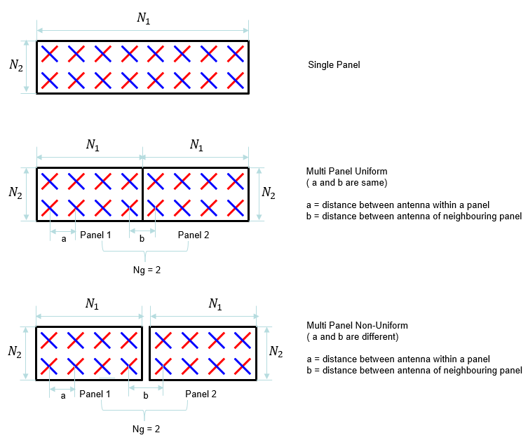
使用这个定义,我们可以将每个码本的天线阵列可视化如下。 正如您在此处看到的,您会注意到对于相同数量的 CSI-RS 天线端口,有多种阵列结构选项。 为什么他们提出多种选择? 也就是说,不同选项之间有什么区别。 例如,4x1 阵列和带有 8 个 CSI 端口的 2x2 阵列有什么区别? 这种不同结构造成的主要差异是光束在 3D 空间中的形状。为了更直观的理解,我将另一种类型的笔记放在 www.slide4math.com 中。 查看 www.slide4math.com 中的 [Array Antenna] 菜单。
<Type 1 Single Panel>
| Number of CSI-RS antenna ports | (N1,N2) | CSI Antenna Port Array (Logical Configuration) |
|---|---|---|
| 4 | (2,1) |  |
| 8 | (2,2) |  |
| (4,1) |  | |
| 12 | (3,2) |  |
| (6,1) |  | |
| 16 | (4,2) |  |
| (8,1) |  | |
| 24 | (4,3) |  |
| (6,2) |  | |
| (12,1) |  | |
| 32 | (4,4) |  |
| (8,2) |  | |
| (16,1) |  |
<Type 1 Multi Panel>
| Number of CSI-RS antenna ports | (Ng,N1,N2) | CSI Antenna Port Array (Logical Configuration) |
|---|---|---|
| 8 | (2,2,1) |  |
| 16 | (2,4,1) |  |
| (4,2.1) |  | |
| (2,2,2) |  | |
| 32 | (2,8,1) |  |
| (4,4,1) |  | |
| (2,4,2) |  | |
| (4,2,2) |  |
TDocs与TS关联
如上所述,仅仅通过阅读3GPP TS规范很难理解关于CSI-RS码本的规范。 因此,就我而言,我经常查看各种 TDoc,有时还会查看有关 5G 物理层的教科书。 然而,在许多情况下,很难在 TDoc/Textbook 所说的内容与 3GPP TS 所说的内容之间找到直接联系。 在本节中,我将提供一些技巧和提示,说明如何将您通常从 TDoc/Textbook 看到的内容与 3GPP TS 指定的内容相关联。
我想向您展示的第一件事是下面显示的链接。 在大多数 TDocs 和教科书中,他们将 CSI Codebook 描述为 W = W1 * W2(两个矩阵的组合),但 3GPP TS 并没有以相同的方式明确地描述它。 3GPP TS 只是列出一大堆表格。 TDoc 中的 Codebook 与 3GPP TS 之间的联系可以说明如下。
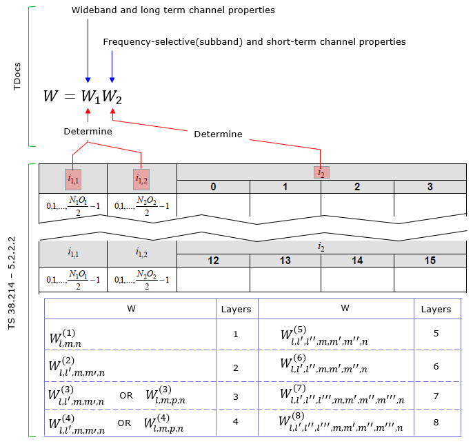
进一步关注码本矩阵格式,3GPP TS 根据层数和其他一些参数定义了各种不同形式的 W 矩阵,如下所示。
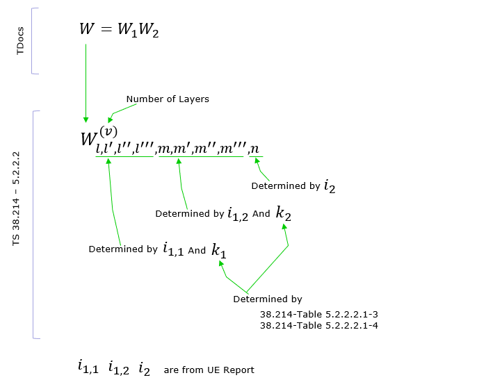
NOTE :关于W矩阵的推导以及矩阵各元素的含义,建议大家参考[Ref 13]。 多为LTE CSI Codebook设计,但NR CSI Codebook设计(尤其是Type 1)的基本概念是继承自LTE CSI Codebook设计。
您可能会从上面提到的内容中注意到,有几个参数标记为“i something”,例如 i1_1、i1_2、i_2。 根据我上面提到的,您会发现 i1_x(即 i1_1、i1_2 等)确定宽带属性,而 i2 确定子带属性。 这种关系在 38214-5.2.2.2 中指定如下(在我的注释中,i1_3 没有明确描述。我会在以后有机会解释每个特定的 CSI 码本表时提到这一点。现在,你只需知道 i1_3 是确定多层码本所需的附加参数)。

W1矩阵的构造过程如下图所示。 如您所见,该矩阵与天线结构相关联。 该矩阵的每一列代表天线阵列形成的每个特定波束的权重向量。 (注意:在某些文档中,向量 X1 ⊗ X2 被描述为 B,其中 ⊗ 表示 Kronecker Product)。
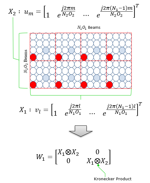
W2 是向量的形式,用于选择 W1 的特定波束(列)。
尽管大多数 TDocs 和教科书都使用两个矩阵 W1 和 W2 解释了预编码矩阵,但您可能无法识别在 3GPP PMI 表中给出的 W 矩阵中明确分离的矩阵。 因此,我想为您提供 3GPP PMI 表中给出的 W 矩阵的整体结构。 根据您选择的 PMI 表,您将大致看到如下两种类型的 W 矩阵结构。
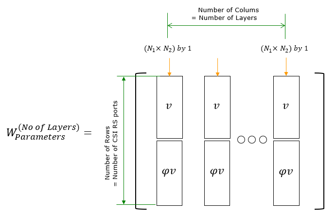
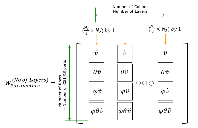
考虑到这个一般结构,选择一个您认为可以处理的非常简单的 PMI 表,像我一样用钢笔和铅笔导出矩阵,就像我在Derivation of W matrix Example中所做的那样 。 我在推导过程中可能犯了一些错误,但至少它帮助我对矩阵的结构和含义建立了更清晰的认识。
Note : 通过这篇笔记,我希望您会非常具体地了解如何为特定的 CSI 参考设置导出预编码矩阵。 一旦你设法推导出这样一个矩阵,你就会想了解如何解释矩阵(即矩阵如何应用于要传输的数据)。 为了直观地理解这些矩阵,我建议练习复杂矩阵如何转换一组复杂数据(I/Q 数据)。对于这种类型的练习,我发布了另一种风格的笔记。参考 www.slide4math.com [Engineering]->[1]->[Matrix Complex].
宽带和子带报告配置
如上一节所述,NR 中的 CSI 报告由两个类别(粒度)组成。 一种是宽带属性(Wideband Granularity),另一种是子带属性(Subband Granularity)。 这两个参数可以单独设置并在独立调度中上报,这为CSI框架提供了更高的效率和灵活性(虽然可能让我们难以理解机制)。
根据 38.214 - 5.2.1.4,宽带和子带报告属性可以通过 RRC 消息中的 ReportQuantity配置如下:
A CSI Reporting Setting is said to have a wideband frequency-granularity if
- reportQuantity is set to ‘cri-RI-PMI-CQI’, or ‘cri-RI-LI-PMI-CQI’, cqi-FormatIndicator indicates single CQI
- reporting and pmi-FormatIndicator indicates single PMI reporting, or
- reportQuantity is set to ‘cri-RI-i1’ or
- reportQuantity is set to ‘cri-RI-CQI’ or ‘cri-RI-i1-CQI’ and cqi-FormatIndicator indicates single CQI reporting, or
- reportQuantity is set to ‘cri-RSRP’ or ‘ssb-Index-RSRP’
otherwise, the CSI Reporting Setting is said to have a subband frequency-granularity.
PMI Tables
以下是关于类型、层数、CSI天线端口数和维度的相关性以及具体映射表的总结。 但是从这个汇总表中理解起来并不容易。 要详细了解这些表中的每一个,我建议您先阅读参考部分中的 TDocs(或至少本说明中的高级描述)以获得一些大图,然后您需要像我在示例部分做的那样手动构建一些特定的 PMI 矩阵。
| Type | # of Layers | Antenna Port | CodebookMode | Pcsi-RS | N2 | Ng | Table in 38.214 |
|---|---|---|---|---|---|---|---|
| Type I Single-Panel | 1 | 3000~3001 | Table 5.2.2.2.1-1 | ||||
| 2 | 3000~3001 | Table 5.2.2.2.1-1 | |||||
| 1 | 3000~2999 + Pcsi-RS | 1 | Table 5.2.2.2.1-5 | ||||
| 1 | 3000~2999 + Pcsi-RS | 2 | > 1 | Table 5.2.2.2.1-5 | |||
| 1 | 3000~2999 + Pcsi-RS | 2 | 1 | Table 5.2.2.2.1-5 | |||
| 2 | 3000~2999 + Pcsi-RS | 1 | Table 5.2.2.2.1-6 | ||||
| 2 | 3000~2999 + Pcsi-RS | 2 | > 1 | Table 5.2.2.2.1-6 | |||
| 2 | 3000~2999 + Pcsi-RS | 2 | 1 | Table 5.2.2.2.1-6 | |||
| 3 | 3000~2999 + Pcsi-RS | 1-2 | < 16 | Table 5.2.2.2.1-7 | |||
| 3 | 3000~2999 + Pcsi-RS | 1-2 | >= 16 | Table 5.2.2.2.1-7 | |||
| 4 | 3000~2999 + Pcsi-RS | 1-2 | < 16 | Table 5.2.2.2.1-8 | |||
| 4 | 3000~2999 + Pcsi-RS | 1-2 | >= 16 | Table 5.2.2.2.1-8 | |||
| 5 | 3000~2999 + Pcsi-RS | 1-2 | Table 5.2.2.2.1-9 | ||||
| 6 | 3000~2999 + Pcsi-RS | 1-2 | Table 5.2.2.2.1-10 | ||||
| 7 | 3000~2999 + Pcsi-RS | 1-2 | Table 5.2.2.2.1-11 | ||||
| 8 | 3000~2999 + Pcsi-RS | 1-2 | Table 5.2.2.2.1-12 | ||||
| Type I Multi Panel | 1 | 3000~2999 + Pcsi-RS | 1 | {2,4} | Table 5.2.2.2.2-3 | ||
| 1 | 3000~2999 + Pcsi-RS | 2 | 2 | Table 5.2.2.2.2-3 | |||
| 2 | 3000~2999 + Pcsi-RS | 1 | {2,4} | Table 5.2.2.2.2-4 | |||
| 2 | 3000~2999 + Pcsi-RS | 2 | 2 | Table 5.2.2.2.2-4 | |||
| 3 | 3000~2999 + Pcsi-RS | 1 | {2,4} | Table 5.2.2.2.2-5 | |||
| 3 | 3000~2999 + Pcsi-RS | 2 | 2 | Table 5.2.2.2.2-5 | |||
| 4 | 3000~2999 + Pcsi-RS | 1 | {2,4} | Table 5.2.2.2.2-6 | |||
| 4 | 3000~2999 + Pcsi-RS | 2 | 2 | Table 5.2.2.2.2-6 | |||
| Type II | 1 & 2 | 3000~2999 + Pcsi-RS | Table 5.2.2.2.3-5 | ||||
| Type II Port Selection | 1 & 2 | 3000~2999 + Pcsi-RS | Table 5.2.2.2.4-1 |
< Table 5.2.2.2.1-1: Codebooks for 1-layer and 2-layer CSI reporting using antenna ports 3000 to 3001 >
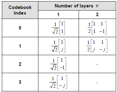
< Table 5.2.2.2.1-5: Codebook for 1-layer CSI reporting using antenna ports 3000 to 2999+P_CSI-RS >
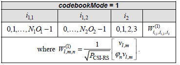
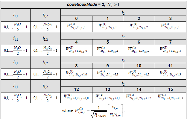
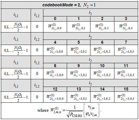
< Table 5.2.2.2.1-6: Codebook for 2-layer CSI reporting using antenna ports 3000 to 2999+P_CSI-RS >
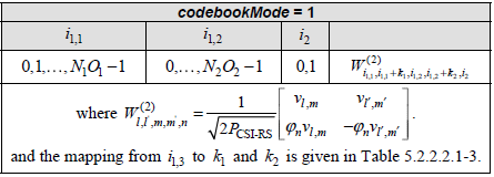
[ Table 5.2.2.2.1-3: Mapping of i1,3 to k1 and k2 for 2-layer CSI reporting ]
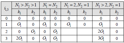
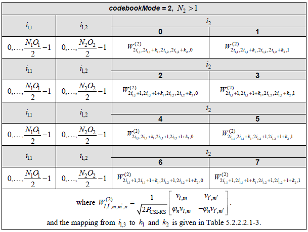
[ Table 5.2.2.2.1-3: Mapping of i1,3 to k1 and k2 for 2-layer CSI reporting ]
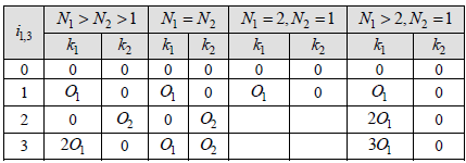
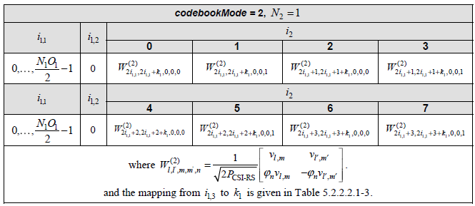
[ Table 5.2.2.2.1-3: Mapping of i1,3 to k1 and k2 for 2-layer CSI reporting ]
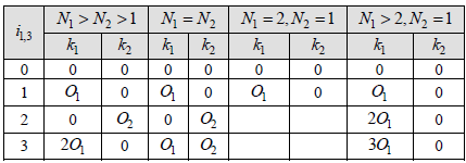
< Table 5.2.2.2.1-7: Codebook for 3-layer CSI reporting using antenna ports 3000 to 2999+P_CSI-RS >
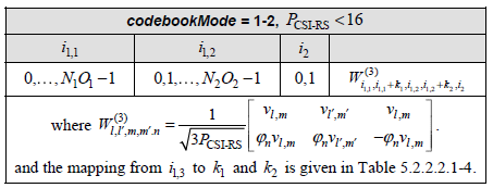
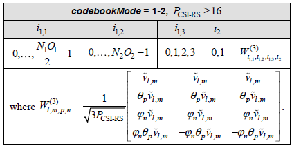
< Table 5.2.2.2.1-4: Mapping of i1,3 to k1 and k2 for 3-layer and 4-layer CSI reporting when P_CSI-RS < 16 >

< Table 5.2.2.2.1-8: Codebook for 4-layer CSI reporting using antenna ports 3000 to 2999+P_CSI-RS >
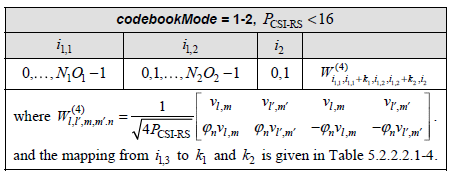
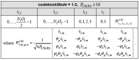
< Table 5.2.2.2.1-4: Mapping of i1,3 to k1 and k2 for 3-layer and 4-layer CSI reporting when P_CSI-RS < 16 >

W1和W2的推导
如前所述,W 矩阵最初设计为表示两个矩阵 W1 和 W2 的乘积(关于原始设计,请参阅[Ref 1] and [Ref13])。但大约一年前我第一次阅读时我很难掌握概念设计上的实际想法,并且不知道每个矩阵代表什么,然后当我找到这个博客([Ref 11])时得到了一点启发,但还不是完整的概念甚至几个月来几乎完全忘记了这个概念。直到一位笔记读者Daniel(HyungJong) Noh 提出了这个问题。我仍然没有清楚地了解这一点,Daniel 设法弄清楚 W1 和 W2 是如何比我更快地推导出来的,他分享了一个例子 展示了两个矩阵的推导,并同意我与读者分享。
在进入 HyungJong 分享的例子之前,让我给你一些额外的说明,以帮助你(我自己)完成思考过程。
首先,我假设现在每个人都知道 W 的定义如下。

基于参考 Ref [1]、[11]、[13] 和 34.214,我们可以将这个方程展开如下。 我认为 W1 现在对你来说能理解的,但是从这个定义来看,W2 的含义仍然是个谜。 您将在下面 HyungJong 的示例中看到更具体的 W2 形式。 (NOTE : ⊗ indicate Kronecker Product)。
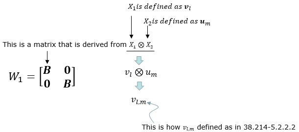

现在让我们来看看HyungJong的例子。 在此示例中,我们假设以下情况 (同W matrix calculation Example 01,但i1,1, i1,2, i2是特定的 (i.e, 保持为通用变量)
-
No of CSI ports = 4
-
N1 = 2, N2 = 1, O1 = 4, O2 = 1
让我们从计算 B 开始。 B 可以根据 Linking TDoc to TS中解释的定义计算如下。

在此基础上,可以如下构造 W1 矩阵。

From the condition given to this example, you can define W2 matrix as follows. You may refer to[ Ref 11] and the seciton 6.12.4.2.1 of [Ref32] for further details on W2 definition.
根据本例给出的条件,您可以如下定义 W2 矩阵。 您可以参考[Ref 11]和 [Ref32]了解有关 W2 定义的更多详细信息。

使用 W1 和 W2,您可以按如下方式计算 W 矩阵。

如果你根据本节开头的定义稍微修改这个 W 矩阵,你可以将这个结果改写如下,你可能会发现它与 38.214 中的表格中描述的形式相同,并且可以理解表中的公式是如何设计的。
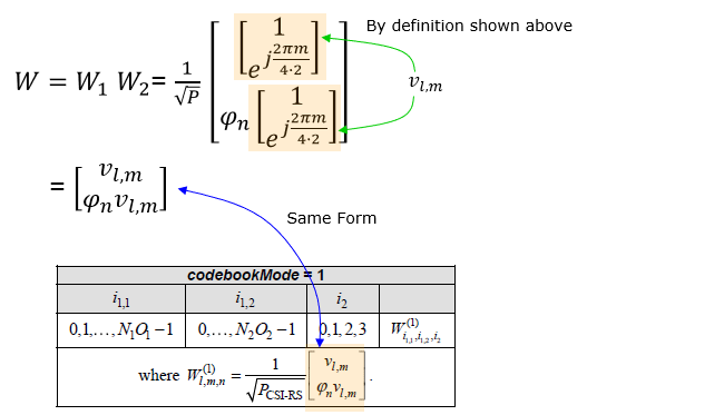
W矩阵的推导示例
在本节中,您将导出的最终矩阵将采用复数元素的形式。 用户数据(即 PDSCH 数据)也是复数形式(I 和 Q 数据)。 最终,您应该能够在大脑中可视化这些矩阵的属性,从而理解这些矩阵。 这是我的另一种笔记,可以帮助您直观地理解矩阵,其中复数元素应用于复杂数据。 在 www.slide4math.com 中播放 [Matrix Complex]。
Example 01 > p4, 1 Layer , N1 = 2, N2 = 1, O1 = 4, O2 = 1, i1,1 = 0 i1,2 = 0 i2 = 0
假设按照下表配置PMI表(Table 5.2.2.2.1-5。
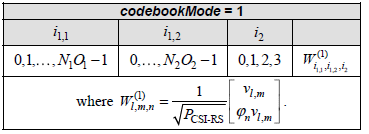
假设我们有上报和天线配置如下:
-
No of CSI ports = 4
-
N1 = 2, N2 = 1, O1 = 4, O2 = 1
-
i1,1 = 0 i1,2 = 0 i2 = 0. This indicates l = i1,1 = 0, m = i1,2 = 0 , n = i2 = 0
现在,让我们将这些参数插入到最终矩阵的所有方程中。 我希望我做对了所有的步骤。 如果您发现任何问题,请告诉我。
-
First, figure out um vector.
-
-
In this example, N2 is 1. So um becomes as follows.
-
-
Next, figure out vl,m vector.
-
-
In this example, l = 0, m = 0. so vl,m become as follows :
-
-
Transposing the vector, we get following vector
-
-
Now calculaing Phi value using the parameter n.
-
-
Plugging into n value given in this example, we get the value as follows.
-
-
Now plugging into the matrix all the vectors we got above
-
-
Plugging l,m,n value given in this example, we get following vector
-
-
Do all the calculation to the end, we get the final matrix(vector) as follows.
-
Example 02 > p4, 1 Layer , N1 = 2, N2 = 1, O1 = 4, O2 = 1, i1,1 = 1 i1,2 = 0 i2 = 1
Let’s assume that PMI table is configured according to following table (Table 5.2.2.2.1-5).
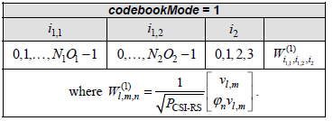
Suppose we have following report and antenna configuration as follows :
-
No of CSI ports = 4
-
N1 = 2, N2 = 1, O1 = 4, O2 = 1
-
i1,1 = 1 i1,2 = 0 i2 = 1. This indicates l = i1,1 = 1, m = i1,2 = 0 , n = i2 = 1
Now, let’s plug these parameters into all the equations that lead to final matrix. I hope I did all the steps right. Let me know if you find anything wrong.
-
First, figure out um vector.
-
-
In this example, N2 is 1. So um becomes as follows.
-
-
Next, figure out vl,m vector.
-
-
In this example, l = 0, m = 0. so vl,m become as follows :
-
-
Transposing the vector, we get following vector
-
-
Now calculaing Phi value using the parameter n.
-
-
Plugging into n value given in this example, we get the value as follows.
-
-
Now plugging into the matrix all the vectors we got above
-
-
Plugging l,m,n value given in this example, we get following vector
-
-
Do all the calculation to the end, we get the final matrix(vector) as follows.
-
Note : 现在最后一步是理解这个向量的含义。 最好的方法是您自己创建一堆 IQ 数据,并将该向量与 IQ 数据相乘,然后查看原始 IQ 数据如何变化。 第二个最好的方法(如果你不想自己做的话)是看看我的视觉数学笔记。See this page at [Engineering]->[1]->[Matrix Complex] in www.slide4math.com . 你也可以将此矩阵解释为 this page 中所示的波束。
Example 03> p4, 2 Layer , N1 = 2, N2 = 1, O1 = 4, O2 = 1, i1,1 = 0 i1,2 = 0 i2= 0, i1,3 = 0
Let’s assume that PMI table is configured according to following table ( Table 5.2.2.2.1-6 ).
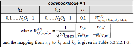
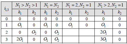
Suppose we have following report and antenna configuration as follows :
-
No of CSI ports = 4
-
N1 = 2, N2 = 1, O1 = 4, O2 = 1
-
i1,1 = 0, i1,2 = 0, i1,3 = 0, i2= 0.
-
This indicates
-
k1 = 0, k2 = 0
-
l = i1,1 = 0, l’= i1,1+k1=0, m = i1,2 = 0, m’ = i1,2+k2 = 0, n = i2 = 0
-
Let’s figure out um vector first.
-

-
Since N2 = 1 in the given condition in this example, um become 1
-

-
Now let’s derive vl,m vector
-

-
Since both l and m is 0 in this example, the vector become as follows.
-

-
Transposing the vector and simplifing it, we get
-

-
Calculating Phi with n given in this example, we get the phi value as follows.
-

-

-
In the same as we did for vl,m, we can calculate vl’,m’ from following equation.
-

-
Plugging the number for l’ and m’, we get following
-

-
Transposing and Simplifying, we get
-

-
Now let’s plug into the final matrix all the vectors and values that we derived above.
-

-
Rewriting the matrix by plugging in parameters (l,l’,m,m’,n), it looks as follows.
-

-
Then, plugging the vectors and values derived above into the matrix, we get the final result as follows.
-

Example 04> p4, 2 Layer , N1 = 2, N2 = 1, O1 = 4, O2 = 1, i1,1 = 0 i1,2 = 0 i2= 1, i1,3 = 1
Let’s assume that PMI table is configured according to following table.
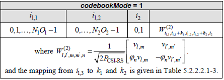
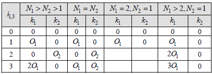
Suppose we have following report and antenna configuration as follows :
-
No of CSI ports = 4
-
N1 = 2, N2 = 1, O1 = 4, O2 = 1
-
i1,1 = 1, i1,2 = 0, i1,3 = 1, i2= 1.
-
This indicates
-
k1 = O1=4, k2 =0 [Note : Since this is the case where N1 > N2 > 1, k1 becomes O1 and k2 becomes 0 when i1,3 = 1]
-
l = i1,1 = 1, l’= i1,1+k1=1+4=5, m = i1,2 = 0, m’ = i1,2+k2 = 0+0 = 0, n = i2 = 1
-
Let’s figure out um vector first.
-

-
Since N2 = 1 in the given condition in this example, um become 1
-

-
Now let’s derive vl,m vector
-

-
Since both l is 1 and m is 0 in this example, the vector become as follows.
-

-
Transposing the vector and simplifing it, we get
-

-
Calculating Phi with n given in this example, we get the phi value as follows.
-

-

-
Now let’s derive vl’,m’ from the following vector.
-

-
Plugging l’ and m’ into the equation, we get a vector as follows.
-

-
Trransposing and Symplifying the vector, we get
-

-
Now let’s derive the final matrix from following equation.
-

-
Plugging the vectors and parameters we got in previous step , we get following
-

-
Plugging the number and simplifying, we get the final result as follows :
-
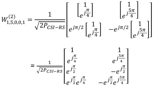
Example 05> p16, 1 Layer , N1 = 8, N2 = 1, O1 = 4, O2 = 1
Let’s assume that we want to figure out the codebook for following configuration. (NOTE : I put the graphical representation of all the possible codebooks in this example in my visual note in 4 pages : here, here, here, here. Check if you can correlate the mathmatical representation shown here and the graphical representation).


Assuming that codebookmode = 2, the codebook table we have to apply is following (Table 5.2.2.2.1-5 )
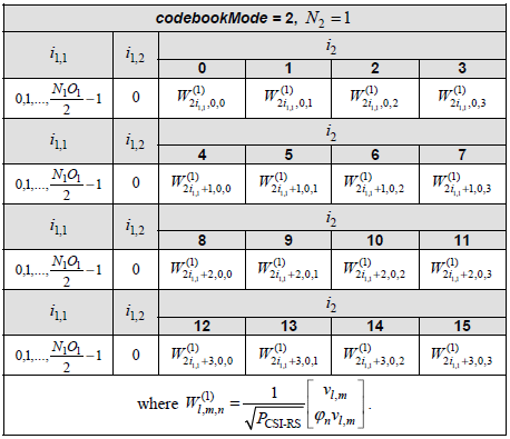
-
Let’s figure out um vector first.
-

-
Since N2 = 1 in the given condition in this example, um become 1
-

-
Now let’s derive vl,m vector
-

-
Since N1 is 8 in this example, we would get a huge vector as shown below. (In this example, I haven’t specified any specific i_x value. I will leave it as a variable)
-

-
Plugging this reslut into the codebook matrix format of Table 5.2.2.2.1-5 and map the result to the logical antenna configuration, it can be illustrated as follow.
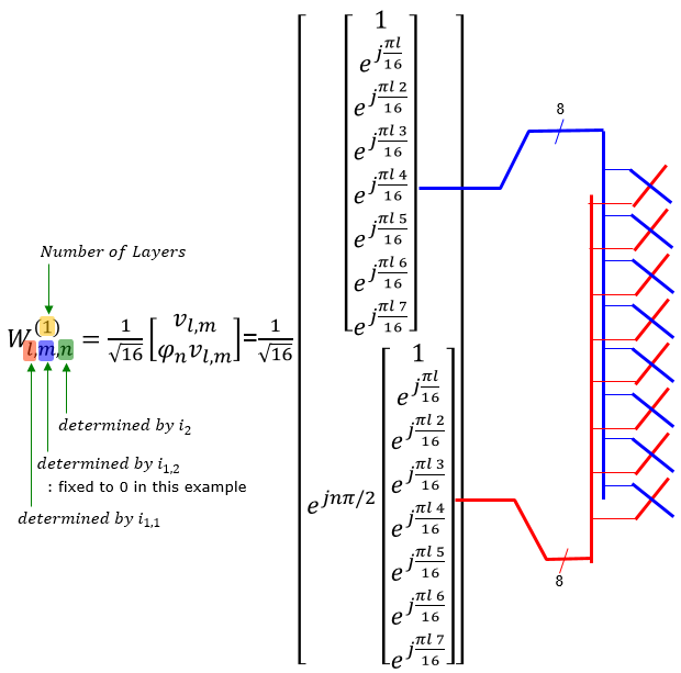
Example 06> p8, 4 Layer , N1 = 4, N2 = 1, O1 = 4, O2 = 1
Let’s assume that we want to figure out the codebook for following configuration


Assuming that codebookmode = 2, the codebook table we have to apply is following (Table 5.2.2.2.1-7 )
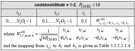
You would notice that there are other variable k1, k2 is required to derive this codebook matrix. Those k1, k2 values are defined in the following table(Table 5.2.2.2.1-4).
-
Let’s figure out um vector first.
-

-
Since N2 = 1 in the given condition in this example, um become 1
-

-
Now let’s derive vl,m vector
-

-
Since N1 is 4 in this example, we would get a vector as shown below. (In this example, I haven’t specified any specific i_x value. I will leave it as a variable)
-

-
Plugging this reslut into the codebook matrix format of Table 5.2.2.2.1-7 and map the result to the logical antenna configuration, it can be illustrated as follow.
-
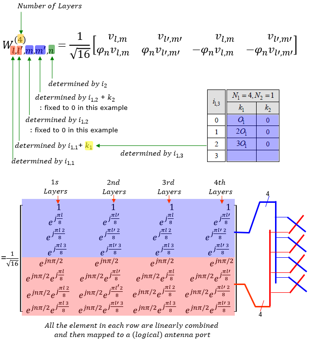
Type II码本的基本公式
Codebook Type II 没有使用任何预定义的 PMI 矩阵。 相反,它基于 UE 测量报告中的各种信息生成波束赋型方程。 为此,应该有一个在 UE 和网络上都知道的公式(数学模板)。 38.214 中描述的详细方程对包括我在内的许多人来说可能看起来太复杂了。
我试图为我找到一个稍微简化的公式形式,以便更容易/更清楚地了解基本概念,以下是我在[Ref34] Amplitude Quantization for Type-2 Codebook Based CSI Feedback in New Radio System中找到的等式之一。 本文是关于type II 码本,而不是Enhanced Codebook Type II码本,但我认为基本概念是相同的。
波束形成矩阵的整体形式如下。 W 矩阵由 Wr,l 组成,其中 r 表示极化,l 表示层。 矩阵的最终结构类似于 将 TDoc 链接到 TS 部分中所示的内容。 不同之处在于如何计算每个矩阵元素。

Now let’s take a look at how each of the matrix elements look like. As shown below, the codebook type II is made up of multiple codebook type I formula and amplitude scaler which are linearly combined.
现在让我们看看每个矩阵元素的样子。 如下图所示,type II码本由多个type I码本公式和幅度缩放器线性组合而成。
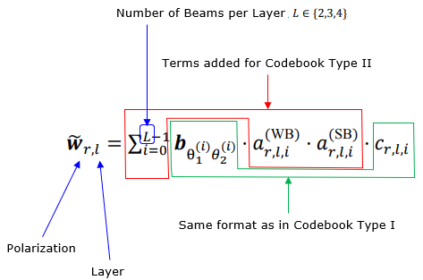
该等式的每个组成部分可以进一步描述如下。
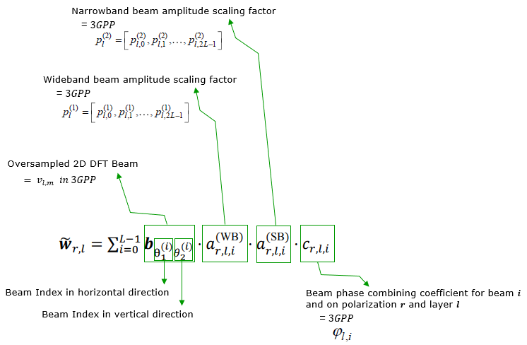
Type II 码本
< 38.214-Table 5.2.2.2.3-5: Codebook for 1-layer and 2-layer CSI reporting using antenna ports 3000 to 2999+P_CSI-RS >
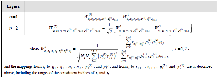
W矩阵的整体结构如下。 ‘v’ 项是生成波束成形矩阵的基本形式的项,该项的逻辑基本上与码本类型 I 中的逻辑相同。有关详细信息,请参阅 W 矩阵示例部分的推导。 “p”项是幅度比例因子,“Phi”项是极化 0 和极化 1 之间的相位组合系数。
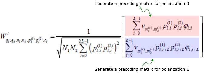
现在让我们来看看公式中使用的每个参数的详细信息。
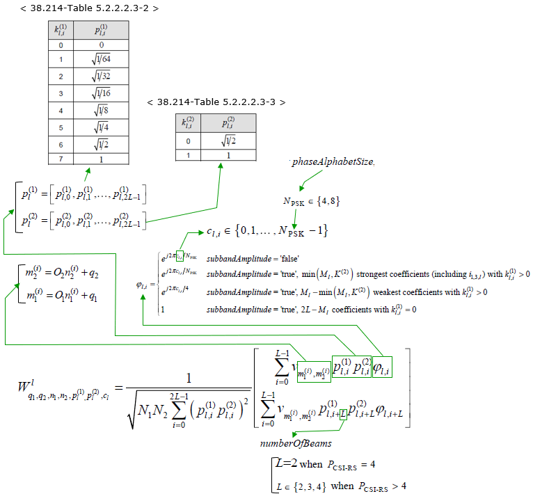
现在的问题是如何确定公式中的每个参数。 这些参数由来自 UE 的 CSI 测量报告确定,总结如下。
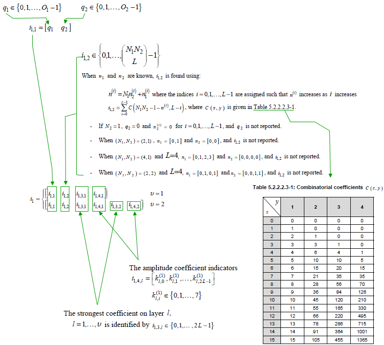
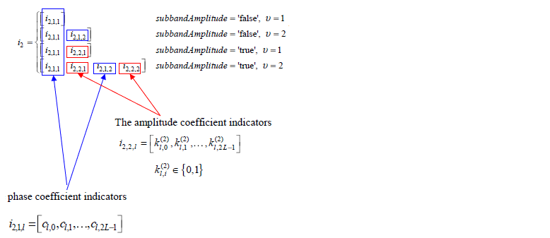
< 38.212-Table 6.3.2.1.2-1: PMI of codebookType= typeII >
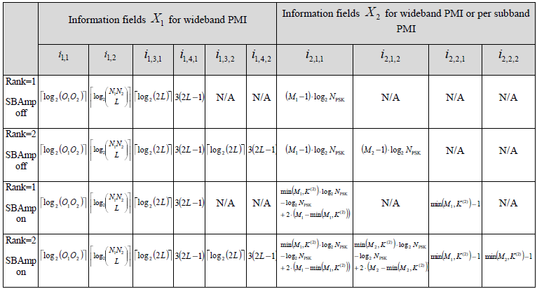
Type II端口选择码本
< 38.214-Table 5.2.2.2.4-1: Codebook for 1-layer and 2-layer CSI reporting using antenna ports 3000 to 2999+P_CSI-RS >
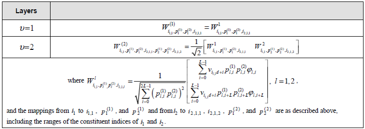
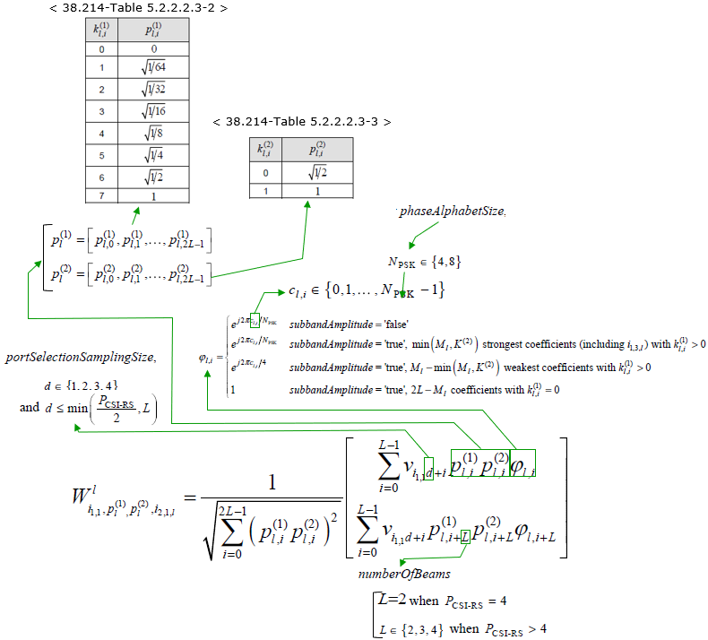
< 38.212-Table 6.3.2.1.2-2: PMI of codebookType= typeII-PortSelection >
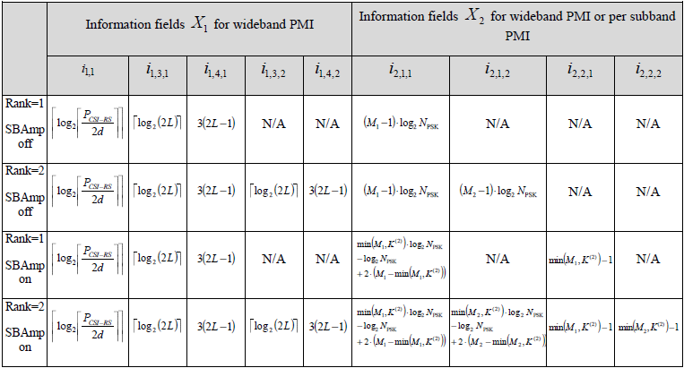
增强型Type II码本
<38.214-Table 5.2.2.2.5-5: Codebook for 1-layer. 2-layer, 3-layer and 4-layer CSI reporting using antenna ports
3000 to 2999+PCSI-RS>
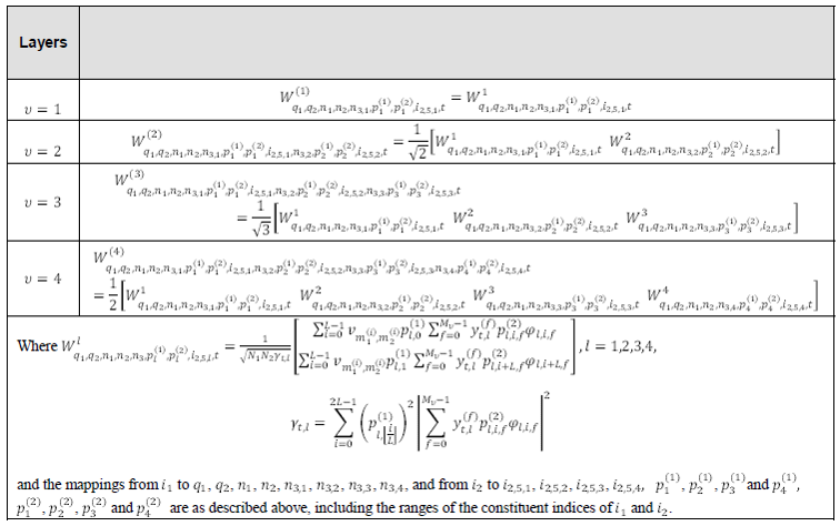
< 38.214-Table 5.2.2.2.5-1 >
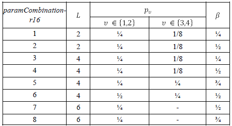
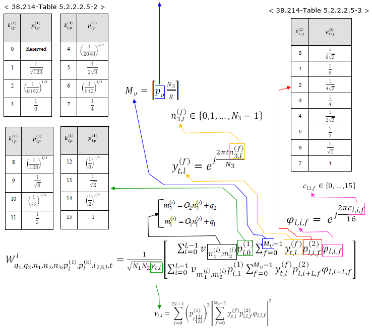
NOTE : 有关选择 paramCombination-r16 的更多详细信息, 参考 this note.
对于增强型码本类型 II,UE 应报告大量信息,总结如下。
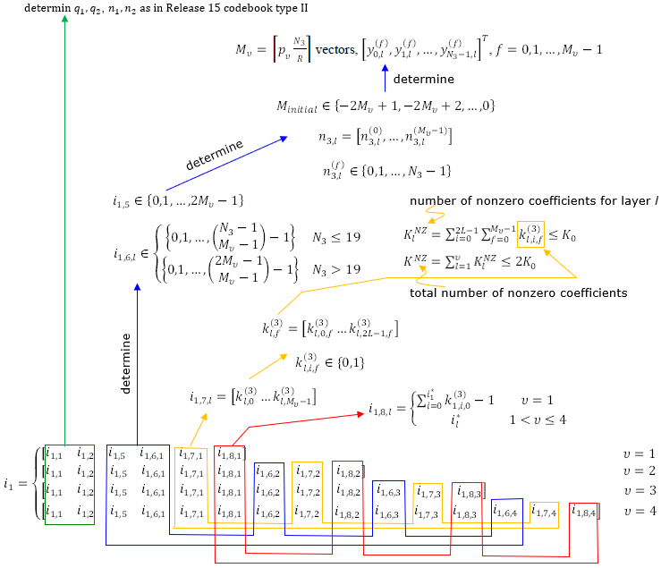
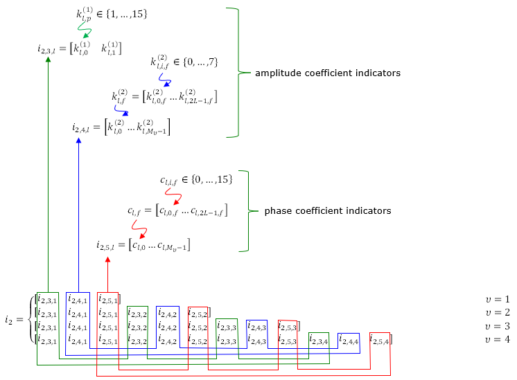
< 38.212-Table 6.3.2.1.2-1A: PMI of codebookType= typeII-r16 >

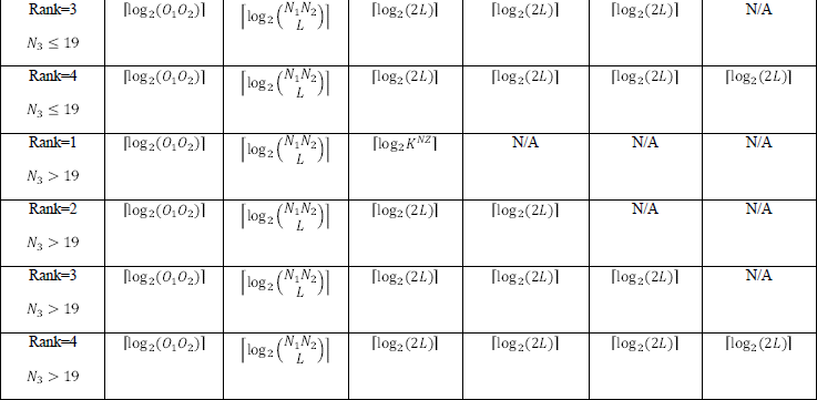
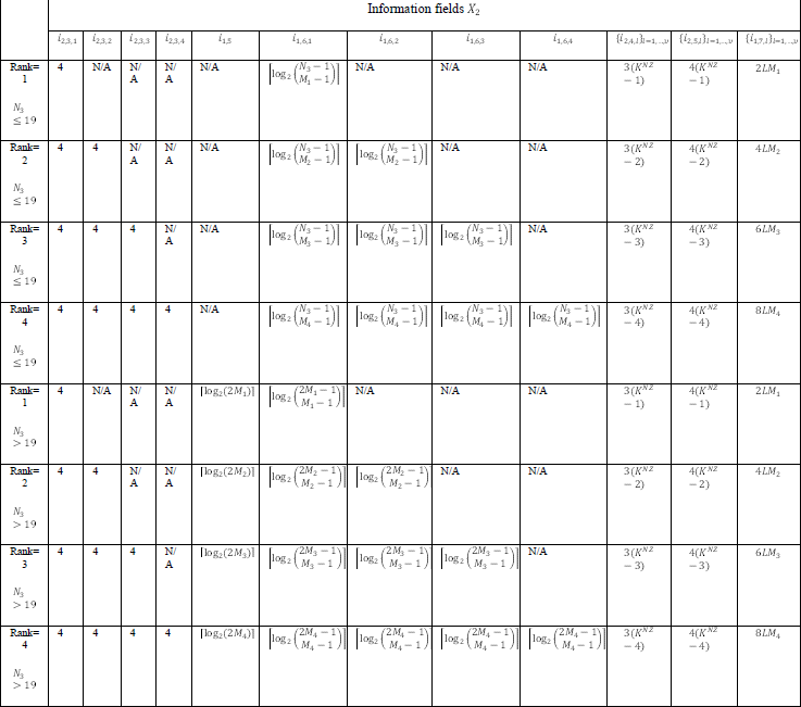
把所有这些放在一起
正如我所提到的,从每个单独的组件(如 CSI-RS 信号生成、码本配置、相关 RRC 参数)方面理解 CSI-RS 的详细机制是非常具有挑战性的,但将所有这些放在一起的整体流程很长一段时间对我来说都仍然是个谜。
就在最近阅读大量 TDoc 并得到我笔记的一位活跃读者的关键帮助后,我认为我对整个过程的理解更接近了。
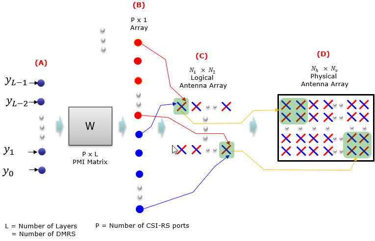
以下是每个过程的简短说明。
A -> B : 这是原始数据(带有 DMRS 的数据)到 CSI-RS 天线端口的过程。 这种映射是通过将数据与 PMI 矩阵(码本)相乘来完成的。 该矩阵的列数与层数(即DMRS天线端口数)相同,该矩阵的原始数与CSI-RS天线端口数相同。 这种映射可以说明如下。
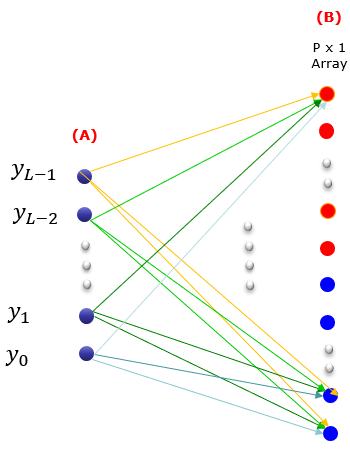
B -> C : 这是将每个 CSI-RS 天线端口映射到 1D 或 2D 交叉极化虚拟天线端口阵列的过程。
C -> D : 这是将阵列中的每个天线元件映射到物理天线阵列的过程。 (D)的数组大小(数组中元素的总数)应该等于或大于©的大小。 在波束成形的情况下,(D)的尺寸将远大于(C)的尺寸。 在此示例中,(C)中的一个极化天线映射到(D)中的四个极化天线,但此映射只是一个示例,映射将在很大程度上取决于供应商。 .
UE是否知道所有这些详细的映射信息?
简而言之,UE 通过 DCI 和 RRC 配置知道 (A) -> (B) -> © 的细节,但对 (D) 一无所知。 但是这种技术的设计方式是 UE 不需要知道 (D)。 我们将其称为“© -> (D) 映射对 UE 透明”。
如何解释 RRC 参数和 i 值?
本节仅介绍码本的 RRC 参数,但码本参数与 CSI RS 参数相关联。关于CSI-RS参数,参考CSI-RS page。
在本节中,我还将讨论与基于码本的 CSI 报告相关的 UE 测量参数。
< Type I-Single Panel >
很长一段时间,我们可能会停留在Type I-SinglePanel 上。 所以现在,我将仅描述 RRC 中 Type I 单面板案例的码本设置。
type1 SEQUENCE {
subType CHOICE {
typeI-SinglePanel SEQUENCE {
nrOfAntennaPorts CHOICE {
two SEQUENCE {
twoTX-CodebookSubsetRestriction BIT STRING (SIZE (6))
},
moreThanTwo SEQUENCE {
n1-n2 CHOICE {
two-one-TypeI-SinglePanel-Restriction BIT STRING (SIZE (8)),
two-two-TypeI-SinglePanel-Restriction BIT STRING (SIZE (64)),
four-one-TypeI-SinglePanel-Restriction BIT STRING (SIZE (16)),
three-two-TypeI-SinglePanel-Restriction BIT STRING (SIZE (96)),
six-one-TypeI-SinglePanel-Restriction BIT STRING (SIZE (24)),
four-two-TypeI-SinglePanel-Restriction BIT STRING (SIZE (128)),
eight-one-TypeI-SinglePanel-Restriction BIT STRING (SIZE (32)),
four-three-TypeI-SinglePanel-Restriction BIT STRING (SIZE (192)),
six-two-TypeI-SinglePanel-Restriction BIT STRING (SIZE (192)),
twelve-one-TypeI-SinglePanel-Restriction BIT STRING (SIZE (48)),
four-four-TypeI-SinglePanel-Restriction BIT STRING (SIZE (256)),
eight-two-TypeI-SinglePanel-Restriction BIT STRING (SIZE (256)),
sixteen-one-TypeI-SinglePanel-Restriction BIT STRING (SIZE (64))
},
typeI-SinglePanel-codebookSubsetRestriction-i2 BIT STRING (SIZE (16))
}
},
typeI-SinglePanel-ri-Restriction BIT STRING (SIZE (8))
},
即使这是 RRC 消息,您也不会从 38.331(RRC 规范)中获得太多详细信息。 您应该查看 38.214 以找到有关这部分的详细信息。 对于 typeI-SinglePanel 案例,请参阅 38.214-5.2.2.2.1。 以下是一些重要的声明。
Antenna Port : 根据天线端口的数量,端口号分配如下。
| Number of Antenna Port | Port Numbers |
|---|---|
| 4 | 3000~3003 |
| 8 | 3000~3007 |
| 12 | 3000~3011 |
| 16 | 3000~3015 |
| 24 | 3000~3023 |
| 32 | 3000~3031 |
PMI and i value mapping : PMI 和相关的 i 值由层数确定,如下所示。
| Number of Layers | i parameters |
|---|---|
| 1,5,6,7,8 | i1,1 , i1,2 , i2 |
| 2,3,4 | i1,1 , i1,2 , i1,3 , i2 |
PCSI-RS(The number of CSI-RS ports) : 它由 (2 x N1 x N2) 确定. See Antenna Configuration Table for Type I single pannel for further details.
< Type II >
type2 SEQUENCE {
subType CHOICE {
typeII SEQUENCE {
n1-n2-codebookSubsetRestriction CHOICE {
two-one BIT STRING (SIZE (16)),
two-two BIT STRING (SIZE (43)),
four-one BIT STRING (SIZE (32)),
three-two BIT STRING (SIZE (59)),
six-one BIT STRING (SIZE (48)),
four-two BIT STRING (SIZE (75)),
eight-one BIT STRING (SIZE (64)),
four-three BIT STRING (SIZE (107)),
six-two BIT STRING (SIZE (107)),
twelve-one BIT STRING (SIZE (96)),
four-four BIT STRING (SIZE (139)),
eight-two BIT STRING (SIZE (139)),
sixteen-one BIT STRING (SIZE (128))
},
typeII-RI-Restriction BIT STRING (SIZE (2))
},
typeII-PortSelection SEQUENCE {
portSelectionSamplingSize ENUMERATED {n1, n2, n3, n4} OPTIONAL,
typeII-PortSelectionRI-Restriction BIT STRING (SIZE (2))
}
},
phaseAlphabetSize ENUMERATED {n4, n8},
subbandAmplitude BOOLEAN,
numberOfBeams ENUMERATED {two, three, four}
}
根据 38.214-5.2.2.2.3,以下是一些重要声明。
Antenna Port : 根据天线端口的数量,端口号分配如下。
| Number of Antenna Port | Port Numbers |
|---|---|
| 4 | 3000~3003 |
| 8 | 3000~3007 |
| 12 | 3000~3011 |
| 16 | 3000~3015 |
| 24 | 3000~3023 |
| 32 | 3000~3031 |
PMI and i value mapping : PMI 和相关的 i 值由层数确定,如下所示。
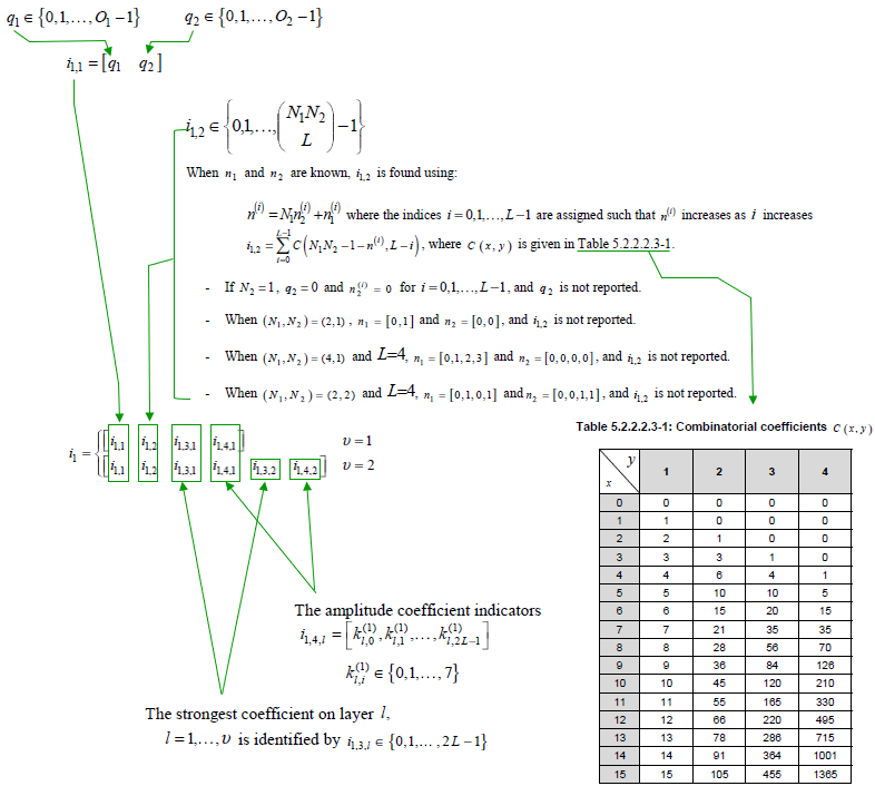
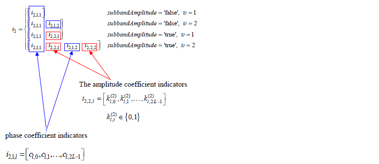
< Enhanced Type II >
CodebookConfig-r16 ::= SEQUENCE {
codebookType CHOICE {
type2 SEQUENCE {
subType CHOICE {
typeII-r16 SEQUENCE {
n1-n2-codebookSubsetRestriction-r16 CHOICE {
two-one BIT STRING (SIZE (16)),
two-two BIT STRING (SIZE (43)),
four-one BIT STRING (SIZE (32)),
three-two BIT STRING (SIZE (59)),
six-one BIT STRING (SIZE (48)),
four-two BIT STRING (SIZE (75)),
eight-one BIT STRING (SIZE (64)),
four-three BIT STRING (SIZE (107)),
six-two BIT STRING (SIZE (107)),
twelve-one BIT STRING (SIZE (96)),
four-four BIT STRING (SIZE (139)),
eight-two BIT STRING (SIZE (139)),
sixteen-one BIT STRING (SIZE (128))
},
typeII-RI-Restriction-r16 BIT STRING (SIZE(4))
},
typeII-PortSelection-r16 SEQUENCE {
portSelectionSamplingSize-r16 ENUMERATED {n1, n2, n3, n4},
typeII-PortSelectionRI-Restriction-r16 BIT STRING (SIZE (4))
}
},
numberOfPMI-SubbandsPerCQI-Subband-r16 INTEGER (1…2),
paramCombination-r16 INTEGER (1…8)
}
}
}
根据 38.214-5.2.2.2.3,以下是一些重要声明。
Antenna Port : 根据天线端口的数量,端口号分配如下。
| Number of Antenna Port | Port Numbers |
|---|---|
| 4 | 3000~3003 |
| 8 | 3000~3007 |
| 12 | 3000~3011 |
| 16 | 3000~3015 |
| 24 | 3000~3023 |
| 32 | 3000~3031 |
paramCombination-r16 : 指定L、pv、beta的参数如下
< 38.214 - Table 5.2.2.2.5-1: Codebook parameter configurations for L, β and pv >
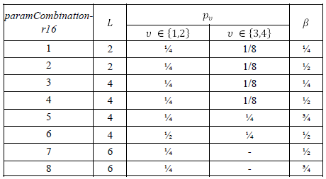
NOTE : 有几个因素会影响可能的设置,根据 38.214 - 5.2.2.2.5 .
The UE is not expected to be configured with paramCombination-r16 equal to
3,4,5,6,7 or 8 when Pcsi-rs = 4
7 or 8 when Pcsi-rs < 32
7 or 8 when higher layer parameter typeII-RI-Restriction-r16 is configured with ri=1 for any i > 1
7 or 8 when R = 2
The parameter R is configured with the higher-layer parameter numberOfPMI-SubbandsPerCQI-Subband. This parameter controls the total number of precoding matrices N3 indicated by the PMI as a function of the number of configured subbands in csi-ReportingBand
CSI RS配置参数
PortIndexFor8Ranks ::= CHOICE {
portIndex8
SEQUENCE{
rank1-8
PortIndex8 OPTIONAL, -- Need R
rank2-8
SEQUENCE(SIZE(2)) OF PortIndex8 OPTIONAL, -- Need R
rank3-8
SEQUENCE(SIZE(3)) OF PortIndex8 OPTIONAL, -- Need R
rank4-8
SEQUENCE(SIZE(4)) OF PortIndex8 OPTIONAL, -- Need R
rank5-8
SEQUENCE(SIZE(5)) OF PortIndex8 OPTIONAL, -- Need R
rank6-8
SEQUENCE(SIZE(6)) OF PortIndex8 OPTIONAL, -- Need R
rank7-8
SEQUENCE(SIZE(7)) OF PortIndex8 OPTIONAL, -- Need R
rank8-8
SEQUENCE(SIZE(8)) OF PortIndex8 OPTIONAL -- Need R
},
portIndex4
SEQUENCE{
rank1-4
PortIndex4 OPTIONAL, -- Need R
rank2-4
SEQUENCE(SIZE(2)) OF PortIndex4 OPTIONAL, -- Need R
rank3-4
SEQUENCE(SIZE(3)) OF PortIndex4 OPTIONAL, -- Need R
rank4-4
SEQUENCE(SIZE(4)) OF PortIndex4 OPTIONAL -- Need R
},
portIndex2
SEQUENCE{
rank1-2
PortIndex2 OPTIONAL, -- Need R
rank2-2
SEQUENCE(SIZE(2)) OF PortIndex2 OPTIONAL -- Need R
},
portIndex1
NULL
}
CodebookConfig ::= SEQUENCE {
codebookType CHOICE {
type1 SEQUENCE {
subType CHOICE {
typeI-SinglePanel SEQUENCE {
nrOfAntennaPorts CHOICE {
two SEQUENCE {
twoTX-CodebookSubsetRestriction BIT STRING (SIZE (6))
},
moreThanTwo SEQUENCE {
n1-n2 CHOICE {
two-one-TypeI-SinglePanel-Restriction
BIT STRING (SIZE (8)),
two-two-TypeI-SinglePanel-Restriction
BIT STRING (SIZE (64)),
four-one-TypeI-SinglePanel-Restriction
BIT STRING (SIZE (16)),
three-two-TypeI-SinglePanel-Restriction
BIT STRING (SIZE (96)),
six-one-TypeI-SinglePanel-Restriction
BIT STRING (SIZE (24)),
four-two-TypeI-SinglePanel-Restriction
BIT STRING (SIZE (128)),
eight-one-TypeI-SinglePanel-Restriction
BIT STRING (SIZE (32)),
four-three-TypeI-SinglePanel-Restriction
BIT STRING (SIZE (192)),
six-two-TypeI-SinglePanel-Restriction
BIT STRING (SIZE (192)),
twelve-one-TypeI-SinglePanel-Restriction
BIT STRING (SIZE (48)),
four-four-TypeI-SinglePanel-Restriction
BIT STRING (SIZE (256)),
eight-two-TypeI-SinglePanel-Restriction
BIT STRING (SIZE (256)),
sixteen-one-TypeI-SinglePanel-Restriction
BIT STRING (SIZE (64))
},
typeI-SinglePanel-codebookSubsetRestriction-i2
BIT STRING (SIZE (16))
}
},
typeI-SinglePanel-ri-Restriction BIT STRING (SIZE (8))
},
typeI-MultiPanel SEQUENCE {
ng-n1-n2 CHOICE {
two-two-one-TypeI-MultiPanel-Restriction
BIT STRING (SIZE (8)),
two-four-one-TypeI-MultiPanel-Restriction
BIT STRING (SIZE (16)),
four-two-one-TypeI-MultiPanel-Restriction
BIT STRING (SIZE (8)),
two-two-two-TypeI-MultiPanel-Restriction
BIT STRING (SIZE (64)),
two-eight-one-TypeI-MultiPanel-Restriction
BIT STRING (SIZE (32)),
four-four-one-TypeI-MultiPanel-Restriction
BIT STRING (SIZE (16)),
two-four-two-TypeI-MultiPanel-Restriction
BIT STRING (SIZE (128)),
four-two-two-TypeI-MultiPanel-Restriction
BIT STRING (SIZE (64))
},
ri-Restriction BIT STRING (SIZE (4))
}
},
codebookMode INTEGER (1..2)
},
type2 SEQUENCE {
subType CHOICE {
typeII SEQUENCE {
n1-n2-codebookSubsetRestriction CHOICE {
two-one
BIT STRING (SIZE (16)),
two-two
BIT STRING (SIZE (43)),
four-one
BIT STRING (SIZE (32)),
three-two
BIT STRING (SIZE (59)),
six-one
BIT STRING (SIZE (48)),
four-two
BIT STRING (SIZE (75)),
eight-one
BIT STRING (SIZE (64)),
four-three
BIT STRING (SIZE (107)),
six-two
BIT STRING (SIZE (107)),
twelve-one
BIT STRING (SIZE (96)),
four-four
BIT STRING (SIZE (139)),
eight-two
BIT STRING (SIZE (139)),
sixteen-one
BIT STRING (SIZE (128))
},
typeII-RI-Restriction
BIT STRING (SIZE (2))
},
typeII-PortSelection SEQUENCE {
portSelectionSamplingSize
ENUMERATED {n1, n2, n3, n4} OPTIONAL,
typeII-PortSelectionRI-Restriction
BIT STRING (SIZE (2))
}
},
phaseAlphabetSize
ENUMERATED {n4, n8},
subbandAmplitude
BOOLEAN,
numberOfBeams
ENUMERATED {two, three, four}
}
}
}
CodebookConfig-r16 ::= SEQUENCE {
codebookType CHOICE {
type2 SEQUENCE {
subType CHOICE {
typeII-r16 SEQUENCE {
n1-n2-codebookSubsetRestriction-r16 CHOICE {
two-one
BIT STRING (SIZE (16)),
two-two
BIT STRING (SIZE (43)),
four-one
BIT STRING (SIZE (32)),
three-two
BIT STRING (SIZE (59)),
six-one
BIT STRING (SIZE (48)),
four-two
BIT STRING (SIZE (75)),
eight-one
BIT STRING (SIZE (64)),
four-three
BIT STRING (SIZE (107)),
six-two
BIT STRING (SIZE (107)),
twelve-one
BIT STRING (SIZE (96)),
four-four
BIT STRING (SIZE (139)),
eight-two
BIT STRING (SIZE (139)),
sixteen-one
BIT STRING (SIZE (128))
},
typeII-RI-Restriction-r16
BIT STRING (SIZE(4))
},
typeII-PortSelection-r16 SEQUENCE {
portSelectionSamplingSize-r16
ENUMERATED {n1, n2, n3, n4},
typeII-PortSelectionRI-Restriction-r16
BIT STRING (SIZE (4))
}
},
numberOfPMI-SubbandsPerCQI-Subband-r16
INTEGER (1..2),
paramCombination-r16
INTEGER (1..8)
}
}
}
参考资料
[1] 3GPP TSG-RAN WG1 #87 R1-1612661 : Advanced CSI Codebook Structure
[2] Multi-Panel MIMO in 5G
[3] 5G New Radio (NR) : Physical Layer Overview and Performance : IEEE Communication Theory Workshop - 2018
[4] A Tutorial on Beam Management for 3GPP NR at mmWave Frequencies
[5] 3GPP TSG-RAN WG1 #86 R1-166579 : Discussion on codebook design to support up to 32 ports CSI RS
[6] 3GPP TSG-RAN WG1 #86 R1-167140 : Codebook for up to 32 ports CSI-RS
[7] 3GPP TSG-RAN WG1 #86 R1-166342 : Codebook Design for Class A CSI Reporting up to 32 Ports
[8] 3GPP TSG-RAN WG1 #86 R1-166445 : Codebook design for {20, 24, 28, 32} ports
[9] Advanced antenna systems for 5G networks
[10] 5G NR (THE NEXT GENERATION WIRELESS ACCESS TECHNOLOGY) - Erik Dahlman, Stefan Parkvall, Johan Skold
[11] Analyze 5G NR Type I SP Codebook
[12] 3GPP TSG-RAN WG1 #90 [R1-171nnnn [DRAFT] Summary on views on CSI reporting for Type I and Type II](https://list.etsi.org/scripts/wa.exe?A3=ind1708D&L=3GPP_TSG_RAN_WG1&E=base64&P=32328799&B=------%3D_NextPart_000_0111_01D31D2C.4A96CE00&T=application%2Fvnd.openxmlformats-officedocument.wordprocessingml.document; name=“R1-17nnnnn Summary of views on CSI feedback for Type I and Type II_ZTE_LGE.docx”&N=R1-17nnnnn Summary of views on CSI feedback for Type I and Type II_ZTE_LGE.docx&attachment=q&XSS=3)
[13] 3GPP TSG RAN WG1 Meeting #82b R1-155490 Rank 1-2 codebook for Class A CSI reporting
[14] RAN1#82-BIS (2015-10-05 - Malmo(SE)) : TDocs
[15] 3GPP TDocs (written contributions) at meeting : R1-85 - 2016-05-23 to 2016-05-27, Nanjing
[16] 3GPP TSG RAN WG1 Meeting #85 : R1-164776 View on class A codebook extension
[17] 3GPP TSG RAN WG1 Meeting #85 : R1-164777 Hybrid PMI codebook based CSI reporting and simulation results
[18] 3GPP TSG RAN WG1 Meeting #85 : R1-164780 Linear combination (LC) codebook based CSI reporting and simulation results
[19] 3GPP TSG RAN WG1 Meeting #85 : R1-164857 Discussion on codebook design to support up to 32 ports CSI-RS
[20] 3GPP TSG-RAN WG1#85 : R1-165097 Class A Codebook Design for up to 32 Ports in Rel-14
[21] 3GPP TDocs (written contributions) at meeting : R1-83 - 2015-11-15 to 2015-11-22, Anaheim
[22] 3GPP TSG RAN WG1 Meeting #83 : R1-156790 Rank 2 codebook – summary of RAN1 proposals and performance
[23] 3GPP TSG RAN WG1 Meeting #83 : R1-156791 Rank 3-8 codebook – summary of RAN1 proposals and performance
[24] 3GPP TSG RAN WG1 Meeting #83 : R1-156831 Codebook design for Class B
[25] 3GPP TSG RAN WG1 Meeting #83 : R1-157003 16 port codebook design and evaluations
[26] 3GPP TSG RAN WG1 Meeting #83 : R1-157164 Codebook design for elevation BF and FD-MIMO
[27] 3GPP TSG-RAN WG1#83 : R1-157208 Class A Codebook Design for Rank 1-2
[28] 3GPP TSG-RAN WG1#83 : R1-157209 Class A Codebook Design for Rank 3-8
[29] 3GPP TSG RAN WG1 Meeting #83 : R1-157300 Codebook Design for rank 2 for 2D antenna arrays
[30] 3GPP TSG RAN WG1 Meeting #83 : R1-157301 Codebook Design for rank 3 to 8 for 2D antenna arrays
[31] 3GPP TSG RAN WG1 Meeting #83 : R1-157427 Samsung, Ericsson, NTT DOCOMO, CATT
[32] 5G Technology -3GPP New Radio Edited by Harri Holma, Antti Toskala, Takehiro Nakamura
[33] Codebook Based Multi-User MIMO for 5G - Lund University
[34] Amplitude Quantization for Type-2 Codebook Based CSI Feedback in New Radio System
[35] 3GPP TSG-RAN WG1 #89 : R1-1709232 WF on Type I and II CSI codebooks
[36] Massive MIMO for New Radio (SamSung Technical White Paper)
[37] Beamforming - How does it work (Ericsson)
[38] 3GPP Workshop : 3GPP 5G Technology and Self Evaluation Results (Wu Yong)
[39] Overhead Reduction of NR type II CSI for NR Release 16 (Nokia)
[40] Massive MIMO for New Radio (SamSung White Paper)
.aspx?mode=view&contributionId=718916)
[6] 3GPP TSG-RAN WG1 #86 R1-167140 : Codebook for up to 32 ports CSI-RS
[7] 3GPP TSG-RAN WG1 #86 R1-166342 : Codebook Design for Class A CSI Reporting up to 32 Ports
[8] 3GPP TSG-RAN WG1 #86 R1-166445 : Codebook design for {20, 24, 28, 32} ports
[9] Advanced antenna systems for 5G networks
[10] 5G NR (THE NEXT GENERATION WIRELESS ACCESS TECHNOLOGY) - Erik Dahlman, Stefan Parkvall, Johan Skold
[11] Analyze 5G NR Type I SP Codebook
[12] 3GPP TSG-RAN WG1 #90 [R1-171nnnn [DRAFT] Summary on views on CSI reporting for Type I and Type II](https://list.etsi.org/scripts/wa.exe?A3=ind1708D&L=3GPP_TSG_RAN_WG1&E=base64&P=32328799&B=------%3D_NextPart_000_0111_01D31D2C.4A96CE00&T=application%2Fvnd.openxmlformats-officedocument.wordprocessingml.document; name=“R1-17nnnnn Summary of views on CSI feedback for Type I and Type II_ZTE_LGE.docx”&N=R1-17nnnnn Summary of views on CSI feedback for Type I and Type II_ZTE_LGE.docx&attachment=q&XSS=3)
[13] 3GPP TSG RAN WG1 Meeting #82b R1-155490 Rank 1-2 codebook for Class A CSI reporting
[14] RAN1#82-BIS (2015-10-05 - Malmo(SE)) : TDocs
[15] 3GPP TDocs (written contributions) at meeting : R1-85 - 2016-05-23 to 2016-05-27, Nanjing
[16] 3GPP TSG RAN WG1 Meeting #85 : R1-164776 View on class A codebook extension
[17] 3GPP TSG RAN WG1 Meeting #85 : R1-164777 Hybrid PMI codebook based CSI reporting and simulation results
[18] 3GPP TSG RAN WG1 Meeting #85 : R1-164780 Linear combination (LC) codebook based CSI reporting and simulation results
[19] 3GPP TSG RAN WG1 Meeting #85 : R1-164857 Discussion on codebook design to support up to 32 ports CSI-RS
[20] 3GPP TSG-RAN WG1#85 : R1-165097 Class A Codebook Design for up to 32 Ports in Rel-14
[21] 3GPP TDocs (written contributions) at meeting : R1-83 - 2015-11-15 to 2015-11-22, Anaheim
[22] 3GPP TSG RAN WG1 Meeting #83 : R1-156790 Rank 2 codebook – summary of RAN1 proposals and performance
[23] 3GPP TSG RAN WG1 Meeting #83 : R1-156791 Rank 3-8 codebook – summary of RAN1 proposals and performance
[24] 3GPP TSG RAN WG1 Meeting #83 : R1-156831 Codebook design for Class B
[25] 3GPP TSG RAN WG1 Meeting #83 : R1-157003 16 port codebook design and evaluations
[26] 3GPP TSG RAN WG1 Meeting #83 : R1-157164 Codebook design for elevation BF and FD-MIMO
[27] 3GPP TSG-RAN WG1#83 : R1-157208 Class A Codebook Design for Rank 1-2
[28] 3GPP TSG-RAN WG1#83 : R1-157209 Class A Codebook Design for Rank 3-8
[29] 3GPP TSG RAN WG1 Meeting #83 : R1-157300 Codebook Design for rank 2 for 2D antenna arrays
[30] 3GPP TSG RAN WG1 Meeting #83 : R1-157301 Codebook Design for rank 3 to 8 for 2D antenna arrays
[31] 3GPP TSG RAN WG1 Meeting #83 : R1-157427 Samsung, Ericsson, NTT DOCOMO, CATT
[32] 5G Technology -3GPP New Radio Edited by Harri Holma, Antti Toskala, Takehiro Nakamura
[33] Codebook Based Multi-User MIMO for 5G - Lund University
[34] Amplitude Quantization for Type-2 Codebook Based CSI Feedback in New Radio System
[35] 3GPP TSG-RAN WG1 #89 : R1-1709232 WF on Type I and II CSI codebooks
[36] Massive MIMO for New Radio (SamSung Technical White Paper)
[37] Beamforming - How does it work (Ericsson)
[38] 3GPP Workshop : 3GPP 5G Technology and Self Evaluation Results (Wu Yong)
[39] Overhead Reduction of NR type II CSI for NR Release 16 (Nokia)
[40] Massive MIMO for New Radio (SamSung White Paper)
最后
以上就是健康煎蛋最近收集整理的关于NR CSI Framework的全部内容,更多相关NR内容请搜索靠谱客的其他文章。


发表评论 取消回复