本文主要讲解Android端Bluetooth Stack(Fluoride),接收到蓝牙Controller上报的ACL链路数据后在蓝牙协议栈的处理流程,如下图。
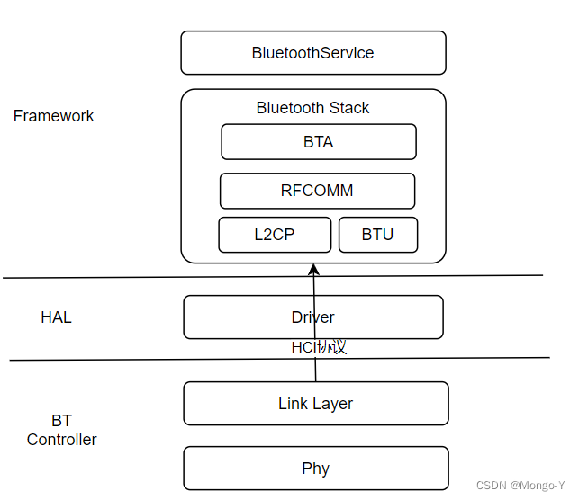
ACL: 异步无连接(Asynchronous Connection-oriented Link[logical transport]),主要用于分组数据传送,比如车载场景连接手机蓝牙时。
L2CAP: 逻辑链路控制和适配协议(Logical Link Control and Adaptation Protocol),负责管理逻辑层提供的逻辑链路。基于该协议不同应用可共享同一个逻辑链路。
BTU : Bluetooth Upper Layer,This is the main task of the Bluetooth Upper Layers unit. It sits in aloop waiting for messages, and dispatches them to the appropiate handlers.
BTA : Bluetooth application layer
Phy: 蓝牙物理层
代码流程分析:
1、HCI_layer处理流程
对接蓝牙驱动接收数据,接收从controller传来的ACL Data
hci_layer_android.cc
class BluetoothHciCallbacks : public IBluetoothHciCallbacks {
   ......
  Return<void> initializationComplete(Status status) {
    CHECK(status == Status::SUCCESS);
    initialization_complete();
    return Void();
  }

  Return<void> hciEventReceived(const hidl_vec<uint8_t>& event) {
    BT_HDR* packet = WrapPacketAndCopy(MSG_HC_TO_STACK_HCI_EVT, event);
    hci_event_received(FROM_HERE, packet);
    return Void();
  }

  // 接收到controller传来的ACL Data
  Return<void> aclDataReceived(const hidl_vec<uint8_t>& data) {
    BT_HDR* packet = WrapPacketAndCopy(MSG_HC_TO_STACK_HCI_ACL, data);
    acl_event_received(packet);
    return Void();
  }

  Return<void> scoDataReceived(const hidl_vec<uint8_t>& data) {
    BT_HDR* packet = WrapPacketAndCopy(MSG_HC_TO_STACK_HCI_SCO, data);
    sco_data_received(packet);
    return Void();
  }
  ......
};
将数据进行重组、分发
通过注册的callback分发至上层模块
hci_layer.cc
void acl_event_received(BT_HDR* packet) {
  btsnoop->capture(packet, true);
  packet_fragmenter->reassemble_and_dispatch(packet);
}

// Callback for the fragmenter to dispatch up a completely reassembled packet
static void dispatch_reassembled(BT_HDR* packet) {
  // Events should already have been dispatched before this point
  CHECK((packet->event & MSG_EVT_MASK) != MSG_HC_TO_STACK_HCI_EVT);
  CHECK(!send_data_upwards.is_null());

  send_data_upwards.Run(FROM_HERE, packet);
}
该回调的注册地方是在bte初始化启动的时候,通过 hci->set_data_cb注册数据接收callback。
bte_main.cc
void bte_main_boot_entry(void) {
  module_init(get_module(INTEROP_MODULE));
  module_init(get_module(PROFILE_CONFIG_MODULE));

  hci = hci_layer_get_interface();
  if (!hci) {
    LOG_ERROR(LOG_TAG, "%s could not get hci layer interface.", __func__);
    return;
  }

  hci->set_data_cb(base::Bind(&post_to_hci_message_loop));

  module_init(get_module(STACK_CONFIG_MODULE));
}
对应的callback回调处理函数
void post_to_hci_message_loop(const tracked_objects::Location& from_here,
                              BT_HDR* p_msg) {
  ......
  hci_message_loop->task_runner()->PostTask(
      from_here, base::Bind(&btu_hci_msg_process, p_msg));
  ......
}
2、BTU处理流程
将Acl数据传递至L2CAP层处理
btu_task.cc
void btu_hci_msg_process(BT_HDR* p_msg) {
/* Determine the input message type. */
  switch (p_msg->event & BT_EVT_MASK) {
    case BT_EVT_TO_BTU_HCI_ACL:
      /* All Acl Data goes to L2CAP */
      l2c_rcv_acl_data(p_msg);
      break;
   ......
  }
}
3、L2CAP层处理
先根据handle查找到对应的LCB(link control block,定义参考下面代码),之后再根据CID取出对应CCB(channel control block,定义参考下面代码),最后通过来L2CAP状态机处理数据。
l2c_main.cc
void l2c_rcv_acl_data(BT_HDR* p_msg) {
  tL2C_LCB* p_lcb;
  tL2C_CCB* p_ccb = NULL;
  ......
  /* Find the LCB based on the handle */
  p_lcb = l2cu_find_lcb_by_handle(handle);

  /*  Look through all active CCBs on a link for a match based
   *  on the local CID. If passed the link pointer is NULL, all
   *  active links are searched. the CCB for this CID */
  p_ccb = l2cu_find_ccb_by_cid(p_lcb, rcv_cid);
  ......

  /* Basic mode packets go straight to the state machine */
  if (p_ccb->peer_cfg.fcr.mode == L2CAP_FCR_BASIC_MODE)
      l2c_csm_execute(p_ccb, L2CEVT_L2CAP_DATA, p_msg);
  else {
       /* eRTM or streaming mode, so we need to validate states first */
       if ((p_ccb->chnl_state == CST_OPEN) ||
           (p_ccb->chnl_state == CST_CONFIG))
           l2c_fcr_proc_pdu(p_ccb, p_msg);
       else
           osi_free(p_msg);
   }
   ......
}
tL2C_LCB及tL2C_CCB的定义如下,两者的关系是一个LCB中可以有多个CCB通过不同的CID区分。
/* Define a link control block. There is one link control block between
 * this device and any other device (i.e. BD ADDR).
 */
typedef struct t_l2c_linkcb {
  bool in_use; /* true when in use, false when not */
  tL2C_LINK_STATE link_state;

  uint16_t handle;        /* The handle used with LM */

  tL2C_CCB_Q ccb_queue; /* Queue of CCBs on this LCB */

  tL2C_CCB* p_pending_ccb;  /* ccb of waiting channel during link disconnect */
  alarm_t* info_resp_timer; /* Timer entry for info resp timeout evt */
  RawAddress remote_bd_addr; /* The BD address of the remote */

  uint8_t link_role; /* Master or slave */
  ......
} tL2C_LCB;

/* Define a channel control block (CCB). There may be many channel control
 * blocks between the same two Bluetooth devices (i.e. on the same link).
 * Each CCB has unique local and remote CIDs. All channel control blocks on
 * the same physical link and are chained together.
 */
typedef struct t_l2c_ccb {
  ......
  tL2C_CHNL_STATE chnl_state; /* Channel state */
  uint16_t local_cid;  /* Local CID */
  uint16_t remote_cid; /* Remote CID */
  tL2C_RCB* p_rcb;      /* Registration CB for this Channel */
  ......
} tL2C_CCB;

typedef struct {
  bool in_use;
  uint16_t psm;
  uint16_t real_psm; /* This may be a dummy RCB for an o/b connection but */
                     /* this is the real PSM that we need to connect to */
#if (L2CAP_UCD_INCLUDED == TRUE)
  tL2C_UCD_REG ucd;
#endif

  tL2CAP_APPL_INFO api;
} tL2C_RCB;

typedef struct {
  tL2CA_CONNECT_IND_CB* pL2CA_ConnectInd_Cb;
  tL2CA_CONNECT_CFM_CB* pL2CA_ConnectCfm_Cb;
  tL2CA_CONNECT_PND_CB* pL2CA_ConnectPnd_Cb;
  tL2CA_CONFIG_IND_CB* pL2CA_ConfigInd_Cb;
  tL2CA_CONFIG_CFM_CB* pL2CA_ConfigCfm_Cb;
  tL2CA_DISCONNECT_IND_CB* pL2CA_DisconnectInd_Cb;
  tL2CA_DISCONNECT_CFM_CB* pL2CA_DisconnectCfm_Cb;
  tL2CA_QOS_VIOLATION_IND_CB* pL2CA_QoSViolationInd_Cb;
  tL2CA_DATA_IND_CB* pL2CA_DataInd_Cb;
  tL2CA_CONGESTION_STATUS_CB* pL2CA_CongestionStatus_Cb;
  tL2CA_TX_COMPLETE_CB* pL2CA_TxComplete_Cb;
} tL2CAP_APPL_INFO;
L2CAP状态机处理函数
l2c_csm.cc
// This function executes the state machine.
void l2c_csm_execute(tL2C_CCB* p_ccb, uint16_t event, void* p_data) {
    ......
    switch (p_ccb->chnl_state) {
      case CST_OPEN:
        l2c_csm_open(p_ccb, event, p_data);
        break;
    ......
}
Android L2CAP 定义的state及event如下:(图源网络,侵权可联系作者删除)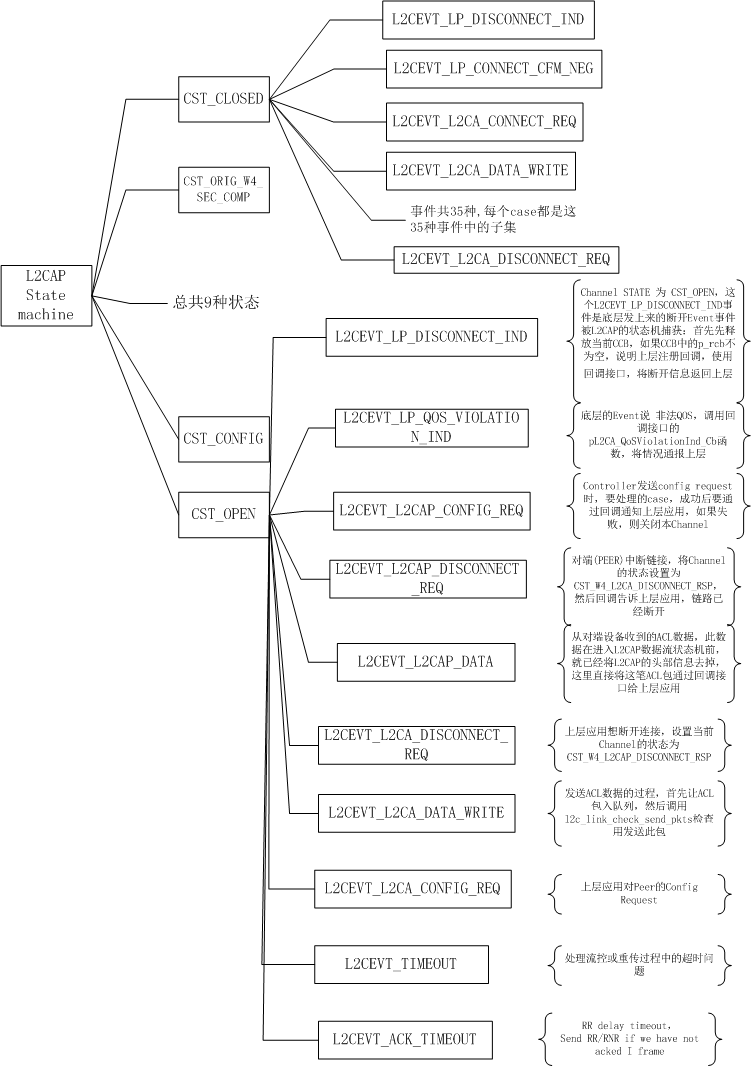
通过pL2CA_DataInd_Cb将数据回调到RFCOMM
// This function handles events when the channel is in OPEN state.
static void l2c_csm_open(tL2C_CCB* p_ccb, uint16_t event, void* p_data) {
   ......
   case L2CEVT_L2CAP_DATA: /* Peer data packet rcvd    */
      if ((p_ccb->p_rcb) && (p_ccb->p_rcb->api.pL2CA_DataInd_Cb))
        (*p_ccb->p_rcb->api.pL2CA_DataInd_Cb)(p_ccb->local_cid,
                                              (BT_HDR*)p_data);
      break;
   ......
}
在RFCOMM task开启时会向L2CAP注册该pL2CA_DataInd_Cb回调接口
rfc_l2cap_if.cc
void rfcomm_l2cap_if_init(void) {
  tL2CAP_APPL_INFO* p_l2c = &rfc_cb.rfc.reg_info;
  p_l2c->pL2CA_ConnectInd_Cb = RFCOMM_ConnectInd;
  p_l2c->pL2CA_ConnectCfm_Cb = RFCOMM_ConnectCnf;
  p_l2c->pL2CA_ConnectPnd_Cb = NULL;
  p_l2c->pL2CA_ConfigInd_Cb = RFCOMM_ConfigInd;
  p_l2c->pL2CA_ConfigCfm_Cb = RFCOMM_ConfigCnf;
  p_l2c->pL2CA_DisconnectInd_Cb = RFCOMM_DisconnectInd;
  p_l2c->pL2CA_DisconnectCfm_Cb = NULL;
  p_l2c->pL2CA_QoSViolationInd_Cb = RFCOMM_QoSViolationInd;
  p_l2c->pL2CA_DataInd_Cb = RFCOMM_BufDataInd;
  p_l2c->pL2CA_CongestionStatus_Cb = RFCOMM_CongestionStatusInd;
  p_l2c->pL2CA_TxComplete_Cb = NULL;

  L2CA_Register(BT_PSM_RFCOMM, p_l2c);
}
4、RFCOMM层处理
通过RFCOMM 状态机处理数据
void RFCOMM_BufDataInd(uint16_t lcid, BT_HDR* p_buf) {
......
  event = rfc_parse_data(p_mcb, &rfc_cb.rfc.rx_frame, p_buf);
  p_port = port_find_dlci_port(rfc_cb.rfc.rx_frame.dlci);
  rfc_port_sm_execute(p_port, event, p_buf);
......
}
RFCOMM 状态机处理函数
rfc_port_fsm.cc
void rfc_port_sm_execute(tPORT* p_port, uint16_t event, void* p_data) {
......
    case RFC_STATE_OPENED:
      rfc_port_sm_opened(p_port, event, p_data);
      break;
......
}
Android定义的RFCOMM Port State如下:
| RFCOMM Port State | 描述 |
|---|---|
| RFC_STATE_CLOSED | |
| RFC_STATE_SABME_WAIT_UA | |
| RFC_STATE_ORIG_WAIT_SEC_CHECK | |
| RFC_STATE_TERM_WAIT_SEC_CHECK | |
| RFC_STATE_OPENED | |
| RFC_STATE_DISC_WAIT_UA |
跟据不同的event类型执行逻辑
void rfc_port_sm_opened(tPORT* p_port, uint16_t event, void* p_data) {
  switch (event) {
  ......
    case RFC_EVENT_UIH:
      rfc_port_uplink_data(p_port, (BT_HDR*)p_data);
      return;
  ......
  }
}
Android定义的RFCOMM支持的帧(Frame)类型如下
| 类型 | 描述 |
|---|---|
| RFC_EVENT_OPEN | |
| RFC_EVENT_CLOSE | |
| RFC_EVENT_CLEAR | |
| RFC_EVENT_DATA | |
| RFC_EVENT_TIMEOUT | |
| RFC_EVENT_SABM | Set Asynchronous Balanced Mode (startup command) |
| RFC_EVENT_UA | Unnumbered Acknowledgement (response when connected) |
| RFC_EVENT_DISC | Disconnect (disconect command) |
| RFC_EVENT_DM | Disconnected Mode (response to a command when disconected) |
| RFC_EVENT_UIH | Unnumbered Information with Header check |
void rfc_port_uplink_data(tPORT* p_port, BT_HDR* p_buf) {
  PORT_DataInd(p_port->rfc.p_mcb, p_port->dlci, p_buf);
}
当从对等方接收到数据缓冲区时,从RFCOMM层调用此函数。
通过数据链路连接标识符(DLCI,Data Link Connection Identifier)找到对应的port,安卓支持最多30个port。
然后通过callback回调给上层应用。
port_rfc.cc
void PORT_DataInd(tRFC_MCB* p_mcb, uint8_t dlci, BT_HDR* p_buf) {
   tPORT* p_port = port_find_mcb_dlci_port(p_mcb, dlci);

  /* If client registered callout callback with flow control we can just deliver
   * receive data */
  if (p_port->p_data_co_callback) {
    /* Another packet is delivered to user.  Send credits to peer if required */
    if (p_port->p_data_co_callback(p_port->inx, (uint8_t*)p_buf, -1,
                                   DATA_CO_CALLBACK_TYPE_INCOMING)) {
      port_flow_control_peer(p_port, true, 1);
    } else {
      port_flow_control_peer(p_port, false, 0);
    }
    // osi_free(p_buf);
    return;
  }

  /* If client registered callback we can just deliver receive data */
  if (p_port->p_data_callback) {
    /* Another packet is delivered to user.  Send credits to peer if required */
    port_flow_control_peer(p_port, true, 1);
    p_port->p_data_callback(p_port->inx, (uint8_t*)(p_buf + 1) + p_buf->offset,
                            p_buf->len);
    osi_free(p_buf);
    return;
  }

  if (p_port->p_callback && events) p_port->p_callback(events, p_port->inx);
}
5、应用层处理逻辑
以AG为例子上层应用注册PORT Callback的地方是在AG服务初始时。
bta_ag_rfc.cc
// Setup RFCOMM port for use by AG.
void bta_ag_setup_port(tBTA_AG_SCB* p_scb, uint16_t handle) {
  uint16_t i = bta_ag_scb_to_idx(p_scb) - 1;

  /* set up data callback if using pass through mode */
  if (bta_ag_cb.parse_mode == BTA_AG_PASS_THROUGH) {
    PORT_SetDataCallback(handle, bta_ag_data_cback_tbl[i]);
  }

  PORT_SetEventMask(handle, BTA_AG_PORT_EV_MASK);
  PORT_SetEventCallback(handle, bta_ag_port_cback_tbl[i]);
}
int PORT_SetEventCallback(uint16_t port_handle, tPORT_CALLBACK* p_port_cb) {
  .....
  p_port = &rfc_cb.port.port[port_handle - 1];
  p_port->p_callback = p_port_cb;
  .....
}
bta_ag_port_cback_tbl定义如下
const tBTA_AG_PORT_CBACK bta_ag_port_cback_tbl[] = {
    bta_ag_port_cback_1, bta_ag_port_cback_2, bta_ag_port_cback_3};
实现为如下函数:
该函数用来处理RFCOMM Port callback,会发送一个BTA_AG_RFC_DATA_EVT消息,参考bta_sys_sendmsg的传输流程请看《BTA消息分发流程》,最终会调用到bta_ag_sm_execute函数
bta_ag_rfc.cc
static void bta_ag_port_cback(UNUSED_ATTR uint32_t code, uint16_t port_handle,
                              uint16_t handle) {
   .......
   BT_HDR* p_buf = (BT_HDR*)osi_malloc(sizeof(BT_HDR));
   p_buf->event = BTA_AG_RFC_DATA_EVT;
   p_buf->layer_specific = handle;
   bta_sys_sendmsg(p_buf);
   .......
}
bta ag 状态机执行函数,这一步的操作是:
1、取出当前状态的event-action关联表,
2、获取当前event对应的state,设置为下一个state;
3、执行当前event对应的action;
bta_ag_main.cc
void bta_ag_sm_execute(tBTA_AG_SCB* p_scb, uint16_t event,
                       tBTA_AG_DATA* p_data) {

  /* look up the state table for the current state */
  state_table = bta_ag_st_tbl[p_scb->state];

  /* set next state */
  p_scb->state = state_table[event][BTA_AG_NEXT_STATE];

  /* execute action functions */
  for (i = 0; i < BTA_AG_ACTIONS; i++) {
    action = state_table[event][i];
    if (action != BTA_AG_IGNORE) {
      (*bta_ag_action[action])(p_scb, p_data);
    } else {
      break;
    }
  }
  ......
}
BTA_AG中定义了4个状态,其中每个状态还定义了每个Event对应的Action1、Action 2及Next State
/* state table */
const tBTA_AG_ST_TBL bta_ag_st_tbl[] = {bta_ag_st_init, bta_ag_st_opening,
                                        bta_ag_st_open, bta_ag_st_closing};
读取并处理来自RFCOMM的数据
bta_ag_act.cc
void bta_ag_rfc_data(tBTA_AG_SCB* p_scb, UNUSED_ATTR tBTA_AG_DATA* p_data) {
  ...
  /* do the following */
  for (;;) {
    /* read data from rfcomm; if bad status, we're done */
    if (PORT_ReadData(p_scb->conn_handle, buf, BTA_AG_RFC_READ_MAX, &len) !=
        PORT_SUCCESS) {
      break;
    }
    ...
    /* run AT command interpreter on data */
    bta_ag_at_parse(&p_scb->at_cb, buf, len);
    if ((p_scb->sco_idx != BTM_INVALID_SCO_INDEX) &&
        bta_ag_sco_is_open(p_scb)) {
      APPL_TRACE_IMP("%s change link policy for SCO", __func__);
      bta_sys_sco_open(BTA_ID_AG, p_scb->app_id, p_scb->peer_addr);
    } else {
      if (strstr(buf, "AT+IPHONEACCEV") != NULL) {
          APPL_TRACE_IMP("%s: AT+IPHONEACCEV received, not setting idle", __func__);
      } else {
          APPL_TRACE_IMP("%s: resetting idle timer", __func__);
          bta_sys_idle(BTA_ID_AG, p_scb->app_id, p_scb->peer_addr);
      }
    }

    /* no more data to read, we're done */
    if (len < BTA_AG_RFC_READ_MAX) {
      break;
    }
  }
}
解析RFCOMM上报的AT指令,未完待续。
/**
 * Parse AT commands.  This function will take the input character string and parse it  *   * for AT commands according to the AT command table passed in the control block.
 **/
void bta_ag_process_at(tBTA_AG_AT_CB* p_cb) {
    ......
    /* if arguments match command capabilities */
    if ((arg_type & p_cb->p_at_tbl[idx].arg_type) != 0) {
      /* if it's a set integer check max, min range */
      if (arg_type == BTA_AG_AT_SET &&
          p_cb->p_at_tbl[idx].fmt == BTA_AG_AT_INT) {
        int_arg = utl_str2int(p_arg);
        if (int_arg < (int16_t)p_cb->p_at_tbl[idx].min ||
            int_arg > (int16_t)p_cb->p_at_tbl[idx].max) {
          /* arg out of range; error */
          (*p_cb->p_err_cback)(p_cb->p_user, false, NULL);
        } else {
          (*p_cb->p_cmd_cback)(p_cb->p_user, p_cb->p_at_tbl[idx].command_id,
                               arg_type, p_arg, int_arg);
        }
      } else {
        (*p_cb->p_cmd_cback)(p_cb->p_user, p_cb->p_at_tbl[idx].command_id,
                             arg_type, p_arg, int_arg);
      }
    }
   ......
}
最后
以上就是粗犷手链最近收集整理的关于蓝牙协议栈源码分析(1)_ACL数据上行处理流程的全部内容,更多相关蓝牙协议栈源码分析(1)_ACL数据上行处理流程内容请搜索靠谱客的其他文章。


发表评论 取消回复