How to confirm production files from manufacture for AD project?
1, target:
Each time when we receive PCB production files from manufacturer, we have to check if they are consistent with our design.
2, tools
Our PCB design tool is Altium designer 18.0
Free Gerber viewer tool: GerberLogix
https://www.easylogix.de/products_detail.php?prog_id=1
3, Comparation our own design files with production files
3.1 human eyes
This is the fastest way to check if a PCB file is simple.
a check list should include:
- Outline is correct? V-cut, Slot etc.?
- All layers are included?
- PCB version is correct?
- Mechanical holes exist?
- Special tracks, keep out lines?
Anyway, only basic info can be checked by human eyes.
3.2 compare by tools
The best option is to compare production files with our own design files by tools and difference can be highlight with different colour.
So our main ideal is to open both production files and our design Gerber files by GerberLogix to see the difference.
But usually the Gerber files do not sit same coordinate systems as show below. There is an offset between 2 files, the main reason is that manufacture usually set the original point at left-bottom corner while the original point in our design file is on one pad as that is easy for us to align different components.
Unfortunately, GerberLogix doesn’t have a function to reset original point. I have searched and found there are some other tools which support to change the original point, but they are not free.
Lucky I have found a work round to fix this issue by Altium designer itself.
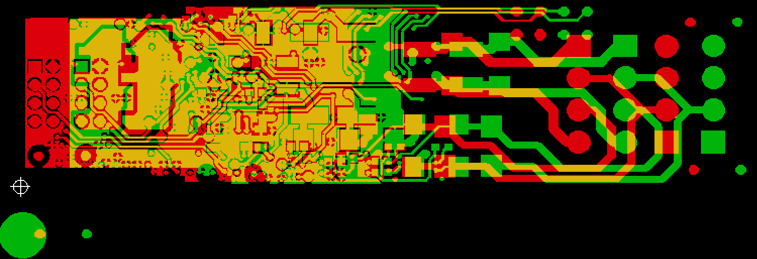
Figure 1, Offset of 2 Gerber files
3.3 Change original point of Gerber file by Altium designer
(1), Create a project in AD
(2), New a CAM Document
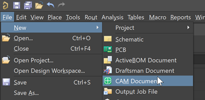
Figure 2, new CAM file
(3), Import manufacture Gerber files
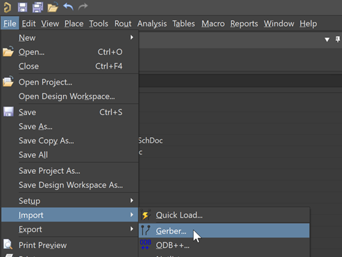
Figure 3, Import Gerber file
(4), Move origin point.
Usually set to a corner or a tiny via.
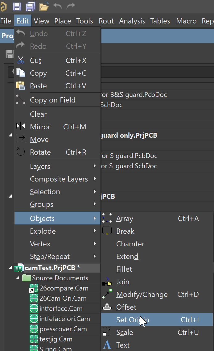
Figure 4, Reset Origin point
(5), Export new Gerber files from AD and save to a new folder (for example folder name is GerberManufacture)
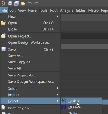
Figure 5, Re-export Gerber files
(6), Repeat step (2) to (4) for importing our own Gerber files and set the origin point to exact same point of step (4).
And export Gerber files to a new folder, for example, folder name is GerberDesign.
(7), Open all gerber files in GerberLogix software from both folder GerberDesign and GerberManufacture. Then compare each layer files. for example compare bottom layer of both files. Figure 6 is bottom layer from manufacture(red colour) while figure 7 is bottom layer from our own design(green cloure).

Figure 6, Bottom layer Gerber file from Manufacture

Figure 7, Bottom layer Gerber file from our own design

Figure 8, Bottom layer Gerber files comparation
The same part will be displayed with yellow colour as it is Red+Green. Any parts whose colour is not yellow is different. We can find that manufacture has narrowed our design as you can see some edge is green.
最后
以上就是魁梧蜜蜂最近收集整理的关于How to confirm production files from manufacture for AD project的全部内容,更多相关How内容请搜索靠谱客的其他文章。


![[LaTeX|翻译]What are .cls and .sty files? How are they different?](https://www.shuijiaxian.com/files_image/reation/bcimg10.png)

发表评论 取消回复